English
 français
 Deutsch
 español
 italiano
 português


Box 16
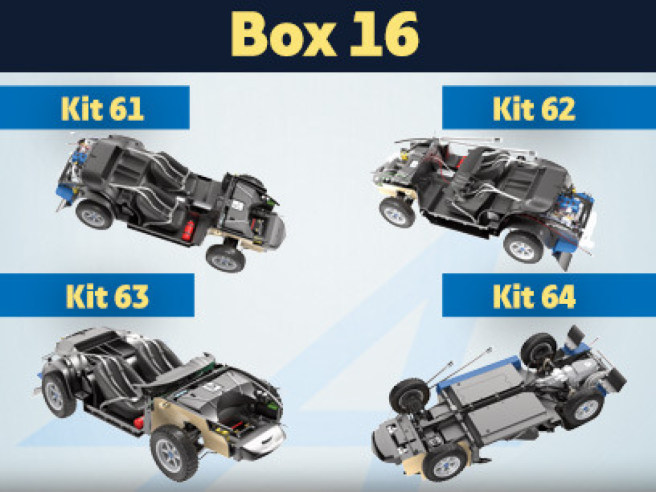
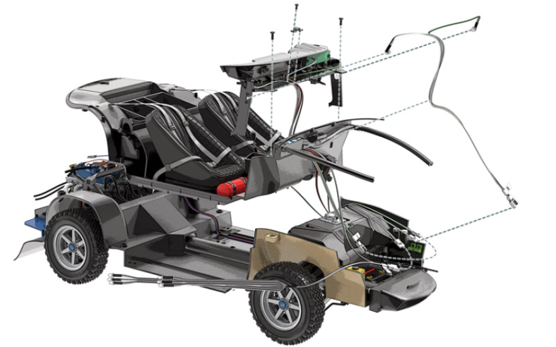
Kit 61 - Assemblage et montage des arceaux de renfort du compartiment moteur
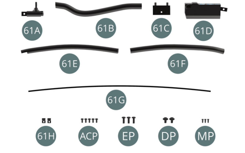
Parts of kit
- 61A Liaison d’arceau
- 61B Arceau de renfort avant
- 61C Boîtier de service
- 61D Boîtier électrique
- 61E Arceau de renfort gauche
- 61F Arceau de renfort droit
- 61G Conduite d’essence
- 61H Attache (x 2)
- ACP Vis M 1,4 x 3 mm (x 5)
- EP Vis M 2,0 x 5 mm (x 3)
- DP Vis M 2,0 x 4 x 5 mm (x 2)
- MP Vis M 1,2 x 3 mm (x 3)

Etape 1
- 61G Fuel line
- 61H Clip (x 2)
- Screw ACP M 1.4 x 3 mm (x 5)
- Screw EP M 2.0 x 5 mm (x 3)
- Screw DP M 2.0 x 4 x 5 mm (x 2)
- Screw MP M 1.2 x 3 mm (x 3)
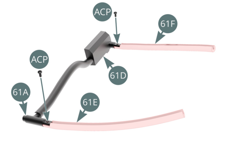
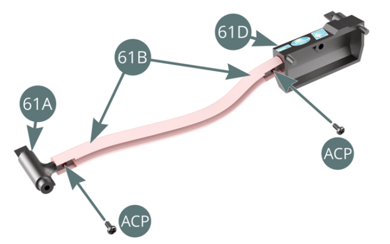
Positionner la liaison d’arceau 61A et le boîtier électrique 61D sur l’arceau de renfort avant 61B, puis les fixer avec deux vis ACP. Positionner les arceaux de renfort gauche 61E et droit 61F respectivement sur la liaison d’arceau 61A et le boîtier électrique 61D, puis les fixer avec deux vis ACP.

Etape 2
Position the arch support link (61A) and the electrical box (61D) on the front reinforcement arch (61B), then secure them with two ACP screws. Position the left and right reinforcement arches (61E&61F) on the arch support (61A) and the electrical box (61D) respectively, then secure them with two ACP screws.

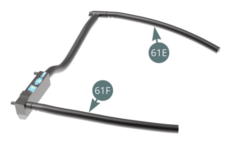
L’arceau de renfort du compartiment moteur est préassemblé.

Etape 3
The engine compartment reinforcement arch is now pre-assembled.
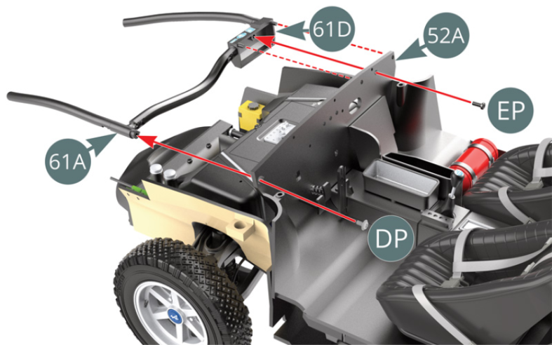
Positionner l’arceau de renfort du compartiment moteur préassemblé sur le plancher d’habitacle 52A par l’intermédiaire de la liaison d’arceau 61A et du boîtier électrique 61D, puis le fixer respectivement avec une vis DP et une vis EP.
Etape 4
Position the pre-assembled engine compartment reinforcement arch on the cabin floor (52A) by means of the arch support (61A) and the electrical box (61D), then secure it with a DP screw and an EP screw respectively.

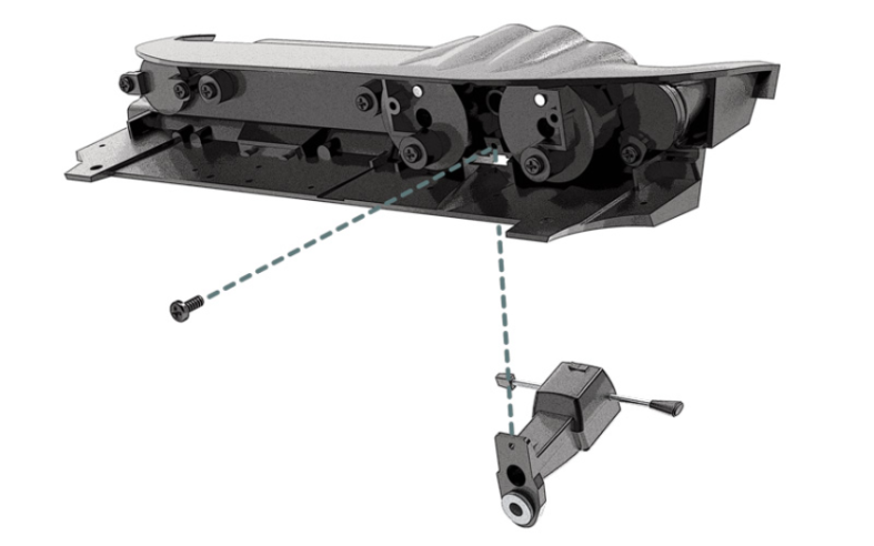
Positionner le boîtier de service 61C sur le plancher d’habitacle 52A et le fixer avec une vis EP (illustration ci-contre).
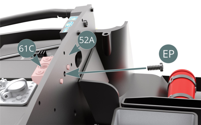
Etape 5
Position the service box (61C) on the cabin floor (52A) and secure it with an EP screw (see illustration opposite).

Positionner les deux attaches 61H sur le plancher d’habitacle 52A et les fixer avec deux vis MP.
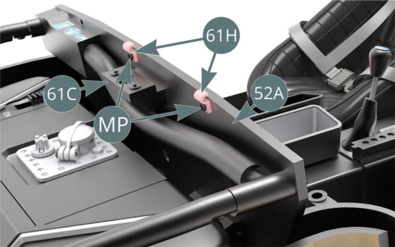
Etape 6
Position the two clips (61H) on the cabin floor (52A) and secure them with two MP screws.

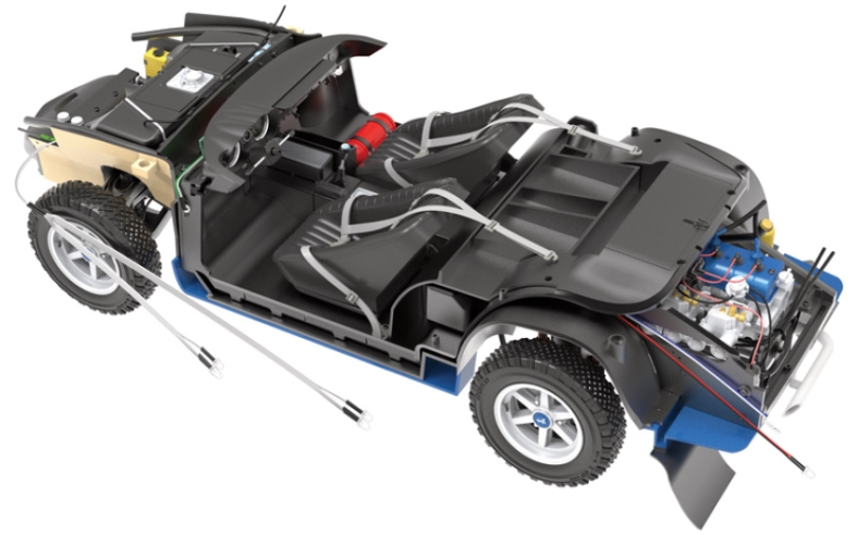
Passer la conduite d’essence 61G dans les deux attaches 61H (flèches rouges).
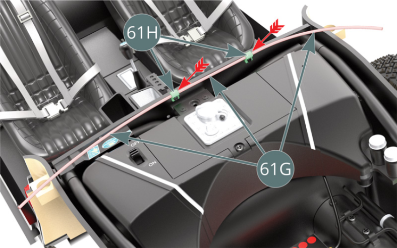
Schéma d’assemblage
Pass the fuel line (61G) through the two brackets (61H) - red arrows.
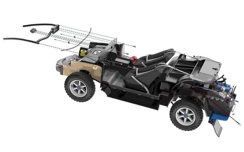
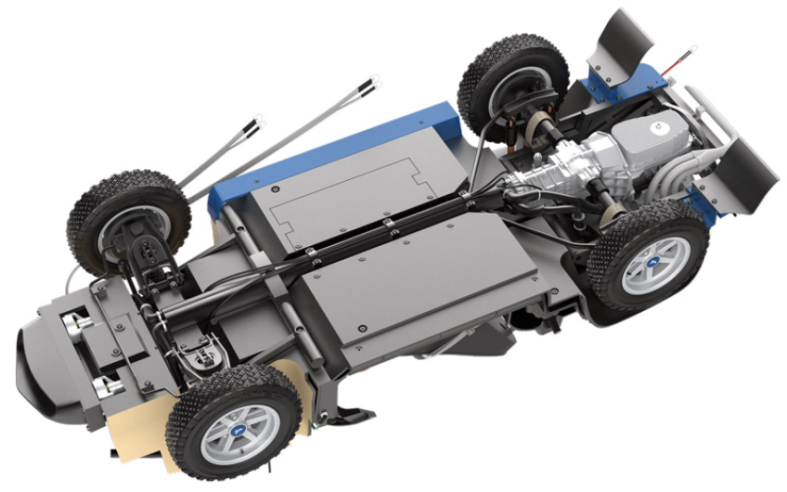
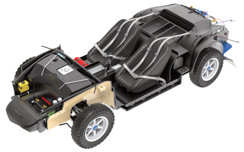
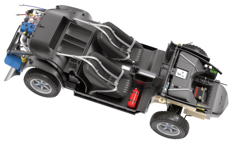
Vue générale

Kit 62 - Assemblage et montage du boîtier de comodo. Montage des câbles électriques
Parts of kit

Etape 1
- 62E Clamp
- 62F Ignition switch
- Screw AP M 1.7 x 4 mm (x 8)
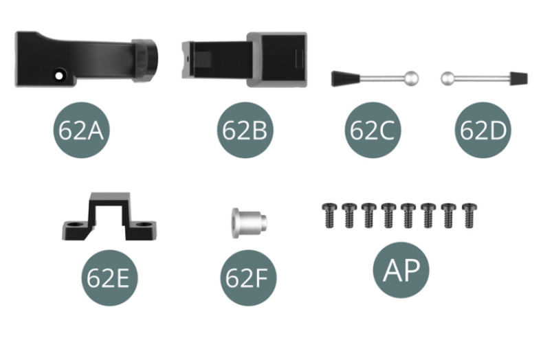
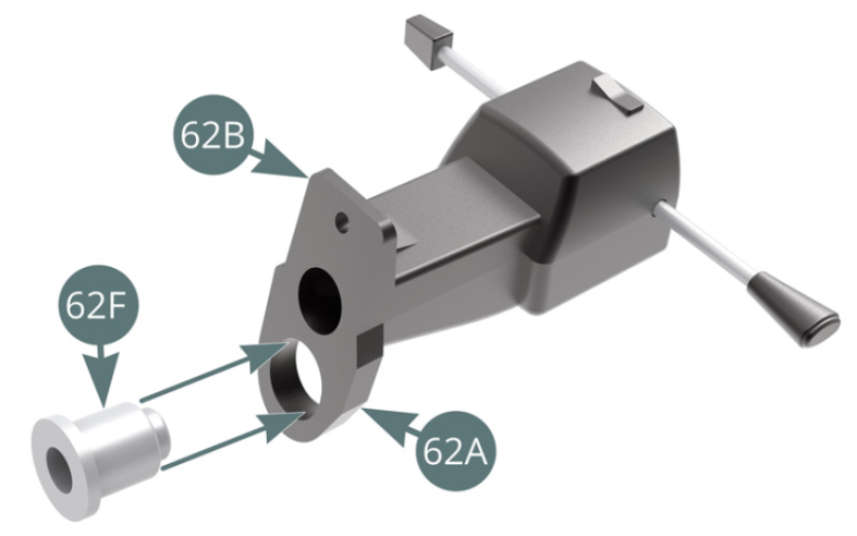
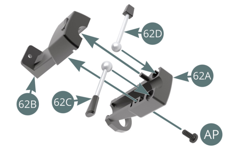
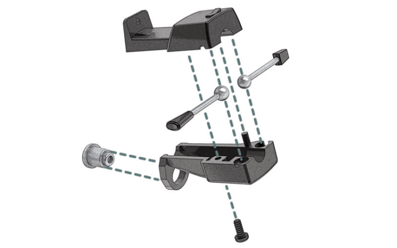
Positionner les rotules situées aux extrémités des commandes de clignotant 62C et d’essuie-glace 62D dans leurs logements respectifs sur le boîtier inférieur de comodo 62A, puis positionner le boîtier supérieur de comodo 62B et le fixer avec une vis AP. Positionner le contacteur de démarrage 62F dans le logement prévu sur le boîtier inférieur de comodo 62A.

Etape 2
Position the ball joints at the ends of the respective turn signal (62C) and windscreen wiper (62D) switches in their respective housings on the lower steering column (62A), then position the upper steering column housing (62B) and secure with an AP screw. Position the ignition switch (62F) in the recess provided on the lower comodo housing (62A).

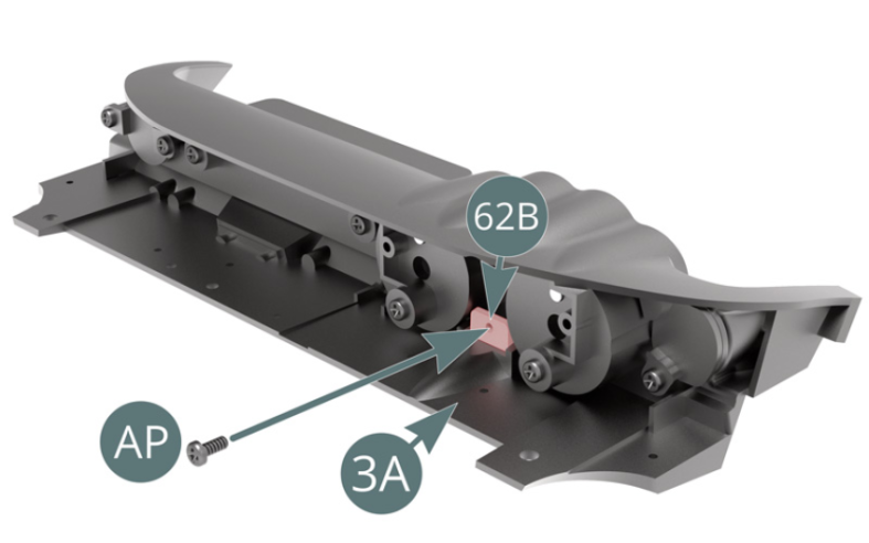
Détacher avec précaution la lampe liseuse 3P du tableau de bord 3A et la mettre de côté pour une utilisation ultérieure. Positionner le boîtier supérieur de comodo 62B dans le logement prévu sur le tableau de bord 3A, puis le fixer par l’arrière avec une vis AP (illustrations ci-dessus).
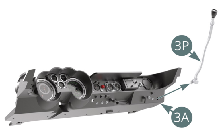
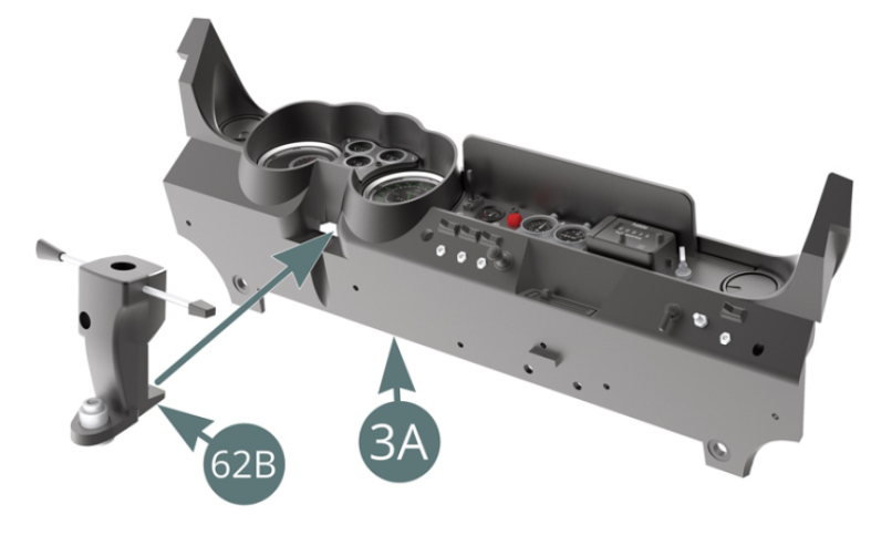
Carefully remove the reading light (3P) from the dashboard (3A) and put it aside for future use. Position the upper steering column housing (62B) in the recess provided on the dashboard (3A), then secure it from behind with an AP screw (see illustrations above).

Etape 3

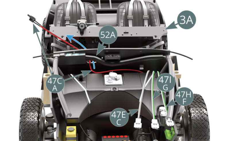
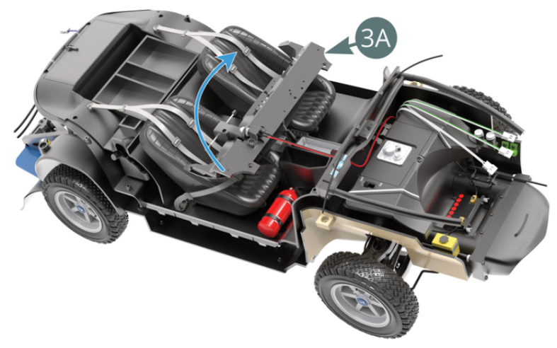
Soulever le plancher d’habitacle 52A et dégager les câbles G (vert - blanc) 47I, F (vert - blanc) 47H et C (gris - blanc) 47 E pour une utilisation ultérieure. Dégager le câble A (rouge - noir) 47C et le passer dans l’ouverture ovale située sur le plancher d’habitacle 52A (flèche bleue). Retourner le tableau de bord 3A et le disposer sur les sièges avant.

Etape 4
Lift the cabin floor (52A) and remove cables G / green - white (47I), F / green - white (47H) and C / grey - white (47E) for future use. Remove cable A / red - black (47C) and pass it through the oval opening in the cabin floor (52A) (blue arrow). Turn the dashboard (3A) over and put it on the front seats.
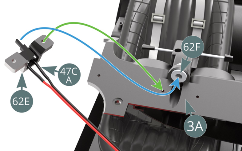
Positionner l’interrupteur du câble A (rouge - noir) 47C sur l’attache 62E. Positionner le bouton de l’interrupteur du câble A 47C dans le contacteur de démarrage 62F (flèche bleue), puis aligner les trous de l’attache 62E avec ceux situés sur le tableau de bord 3A (flèche verte).
Etape 5
Position the A / red - black cable switch (47C) on the clip (62E). Position the switch button for cable A (47C) in the ignition switch (62F) (blue arrow), then align the openings in the clip (62E) with those on the dashboard (3A) (green arrow).

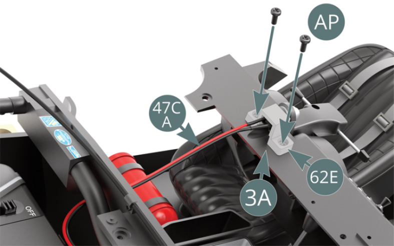
Fixer l’attache 62E sur le tableau de bord 3A avec deux vis AP.

Etape 6
Secure the clamp (62E) to the dashboard (3A) using two AP screws.
Retourner le tableau de bord 3A.

Etape 7
Flip the dashboard (3A) over.
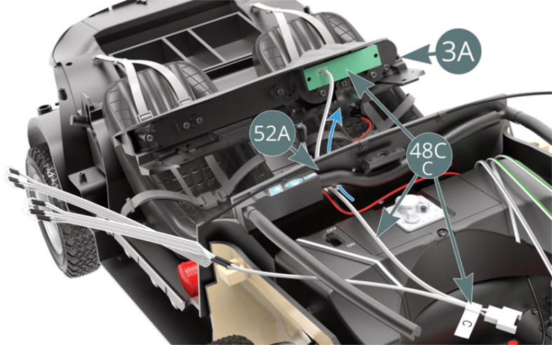
Passer le fil du câble C 48C (avec le circuit imprimé vert) dans l’ouverture ovale située sur le plancher d’habitacle 52A (flèche bleue) et aligner les trous du circuit imprimé avec ceux situés sur le tableau de bord 3A.
Etape 8
Pass the cable wire C (48C) - with the green PCB - through the oval opening in the cabin floor (52A) (blue arrow) and align the openings in the PCB with those in the dashboard (3A).

Fixer le circuit imprimé du câble C 48C sur le tableau de bord 3A avec deux vis AP.
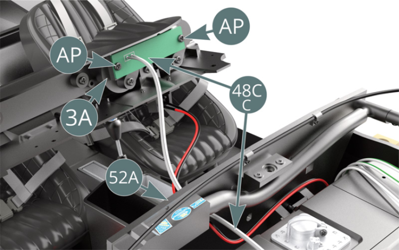
Schéma d’assemblage
Attach the cable C PCB (48C) to the dashboard (3A) using two AP screws.
Vue générale


Kit 63 - Montage du tableau de bord et des panneaux de l’habitacle sur le châssis. Montage des câbles électriques
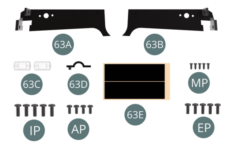
Parts of kit
Etape 1
- Screw MP M 1.2 x 3 mm (x 5)
- Screw IP M 2.3 x 6 mm (x 5)
- Screw AP M 1.7 x 4 mm (x 4)
- Screw EP M 2.0 x 5 mm (x 5)
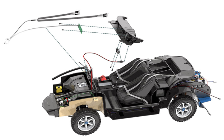
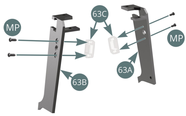
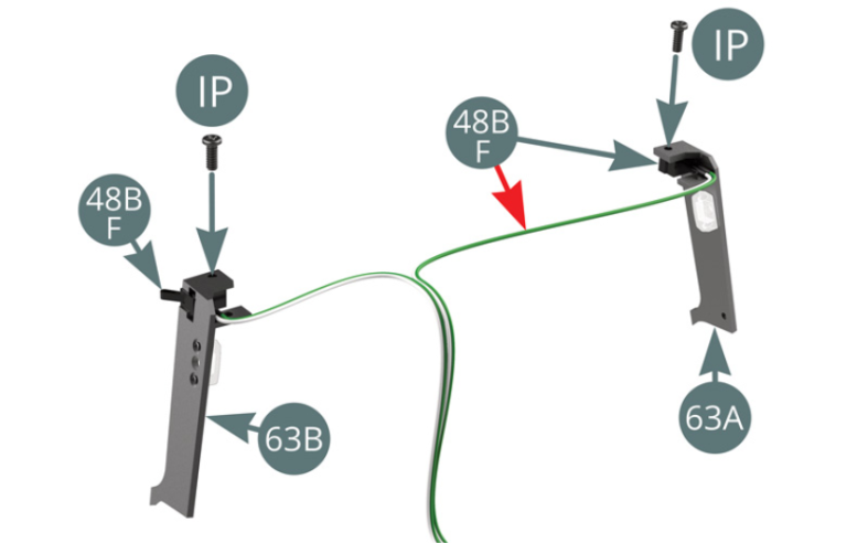
Positionner les éclairages d’habitacle 63C sur les montants latéraux droit 63B et gauche 63A, puis les fixer chacun avec deux vis MP. Positionner les interrupteurs du câble F 48B sur les montants latéraux droits 63B et gauche 63A (fil le plus long comme indiqué par la flèche rouge), puis les fixer avec deux vis IP.


Etape 2
Position the passenger compartment lights (63C) on the right and left side panels (63B&63A), then secure each with two MP screws. Position the F-cable switches (48B) on the right and left side panels (63B&63A) - longest wire as specified by the red arrow - and secure them with two IP screws.
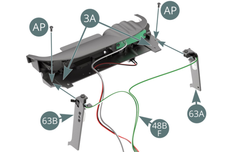
Positionner les montants latéraux droit 63B et gauche 63A sur le tableau de bord 3A, puis les fixer avec deux vis AP. Positionner les lampes LED du câble G 48A dans les prises extérieures des montants latéraux droits 63B et gauche 63A (fil le plus long). Regrouper les cinq câbles puis les fixer ensemble sur le tableau de bord 3A avec l’attache 63D et une vis AP.

Etape 3
Position the right and left side panels (63B&63A) on the dashboard (3A), then fasten them with two AP screws. Position the LED lights from cable G (48A) in the outer sockets on the right and left side panels (63B&63A) - longest wire. Group the five cables together, then secure them to the dashboard (3A) using the clamp (63D) and an AP screw.

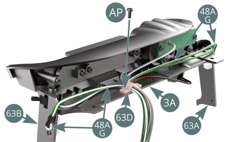
Passer les câbles F 48B et G 48A dans l’ouverture ovale située sur le plancher d’habitacle 52A.

Etape 4
Pass the F and G cables (48B&48A) through the oval opening in the cabin floor (52A).
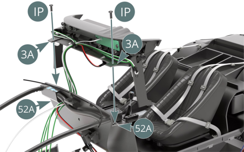
Positionner le tableau de bord 3A sur le plancher d’habitacle 52A et le fixer avec deux vis IP.

Etape 5
Position the dashboard (3A) on the cabin floor (52A) and secure with two IP screws.
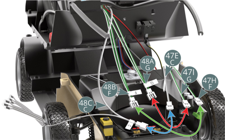
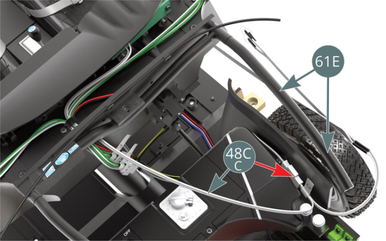
Connecter les câbles G 48A et G 47I, les câbles F 48B et F 47H ainsi que les câbles C 48C et C 47E en respectant les couleurs respectives. Disposer le câble C 48C et ses connecteurs sur le côté du réservoir d’essence (flèche rouge) afin de le dissimuler plus tard sous l’arceau de renfort gauche 61E.


Etape 6
Connect the G cables (48A&47I), the F cables (48B&47H) and the C cables (48C&47E) in accordance with their respective colours. Arrange cable C (48C) and its plugs on the side of the fuel tank (red arrow) to conceal it later under the left-hand reinforcement arch (61E).
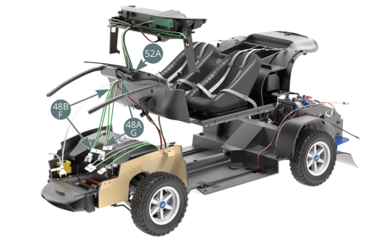
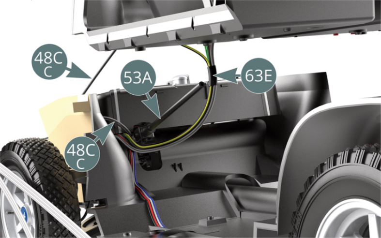
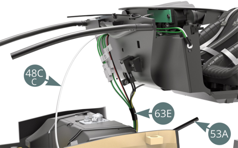
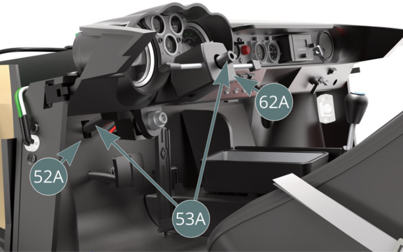
Regrouper tous les câbles, sauf le câble C 48C, puis les faire passer sous la colonne de direction 53A et les attacher ensemble avec un ruban adhésif 63E (illustrations ci-dessus).


Etape 7
Group all the cables together, except cable C (48C), then pass them underneath the steering column (53A) and tape them together (63E) - illustrations above.
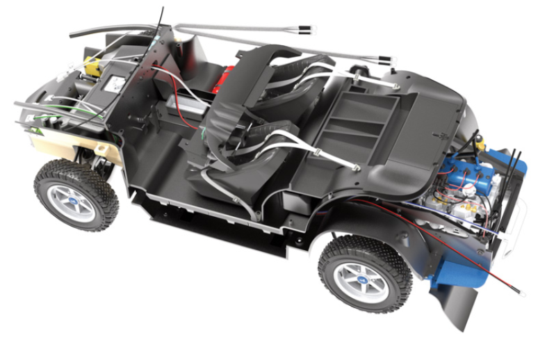
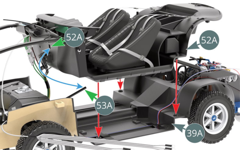
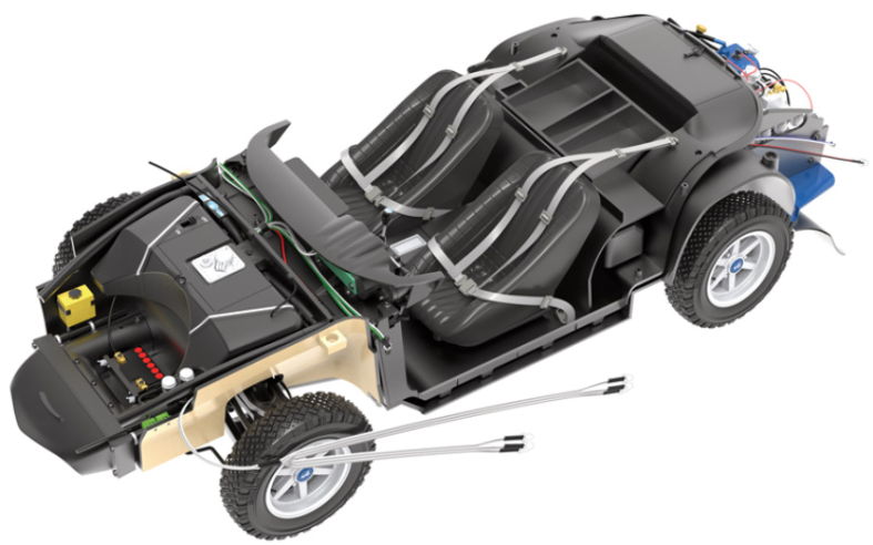
Commencer le montage du plancher d’habitacle 52A sur le plancher du châssis 39A en engageant la colonne de direction 53A dans l’orifice carré situé sur le plancher d’habitacle 52A (flèches verte et bleue).

Etape 8
Start fitting the cabin floor (52A) to the chassis floor (39A) by engaging the steering column (53A) into the square opening located on the cabin floor (52A) - green and blue arrows.
Vérifier que la colonne de direction 53A passe correctement à travers le plancher d’habitacle 52A et le boîtier inférieur de comodo 62A.

Etape 9
Check that the steering column (53A) is properly passed through the cabin floor (52A) and the lower comodo housing (62A).
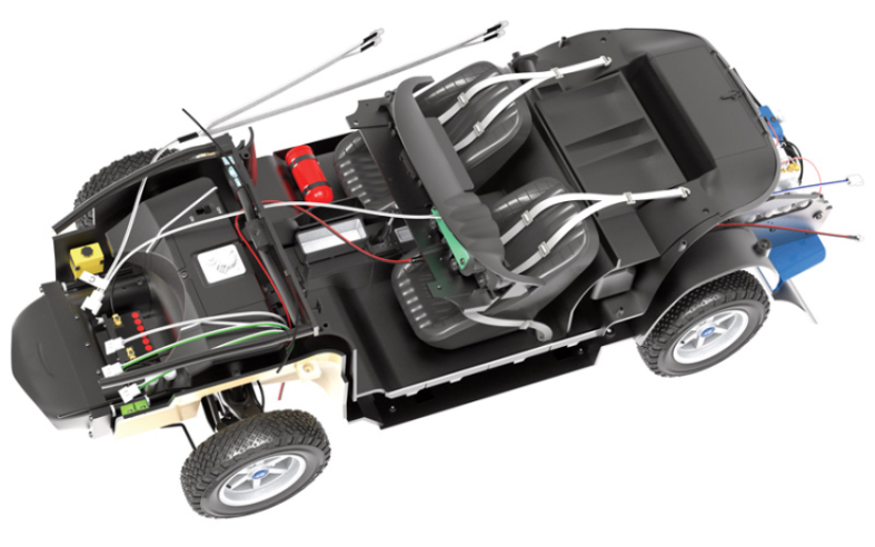
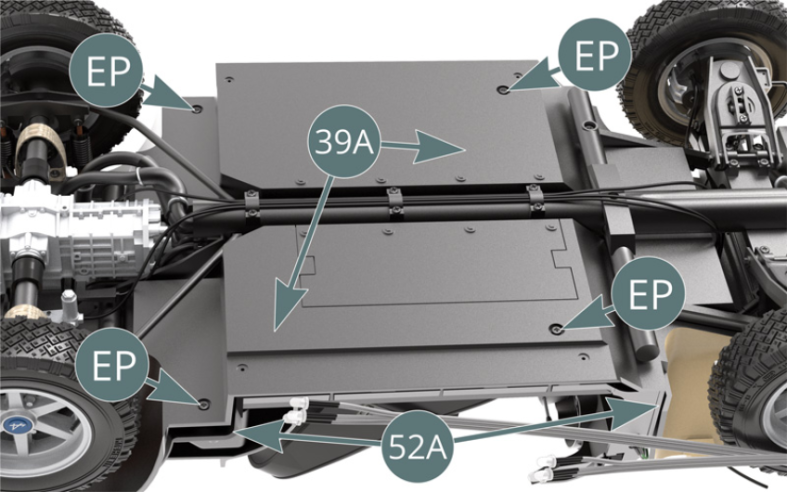
Fixer le plancher d’habitacle 52A sur le plancher du châssis 39A par en dessous avec quatre vis EP.
Etape 10
Secure the cabin floor (52A) – from below - to the chassis floor (39A) using four EP screws.

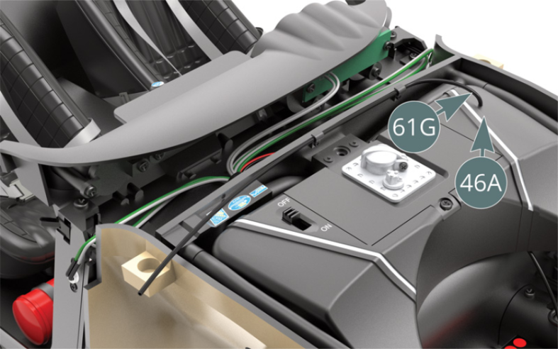
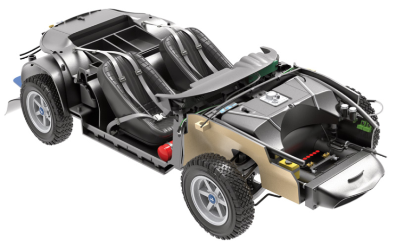
Relier la conduite d’essence 61G au réservoir d’essence 46A.
Etape 11
Connect the fuel line (61G) to the fuel tank (46A).

Les trois câbles suivants restent libres jusqu’à une utilisation ultérieure : câble C 48C (LEDs), câble H 47J (LED) et câble D 47F (connecteur).

Schéma d’assemblage
The following three cables remain free for future use: LED cable C (48C), LED cable H (47J) and cable D connector (47F).

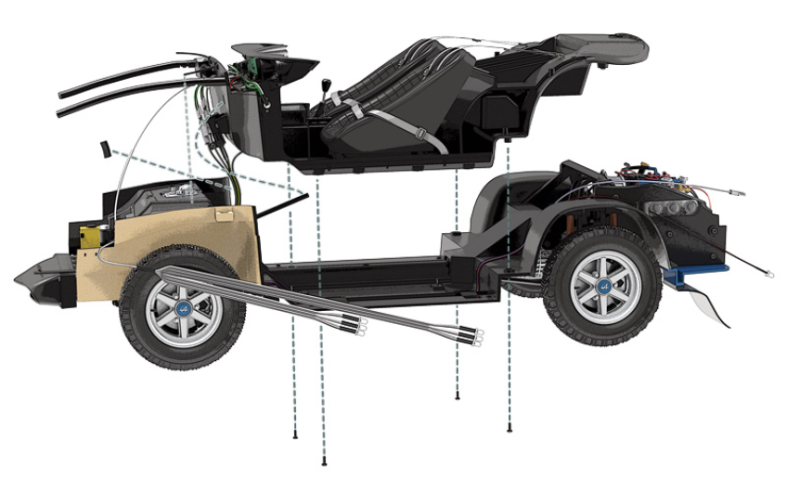
Vue générale
Kit 64 - Montage du bas de caisse gauche sur le châssis
Parts of kit

Etape 1
- Screw SM M 1.7 x 3 mm (x 3)
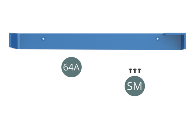
Positionner le bas de caisse 64A sur le plancher du châssis 39A et le fixer avec deux vis SM (illustrations ci-dessus).
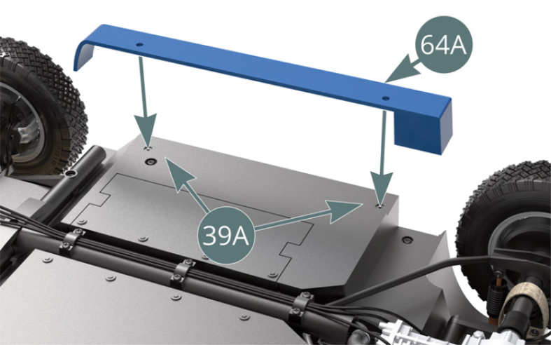
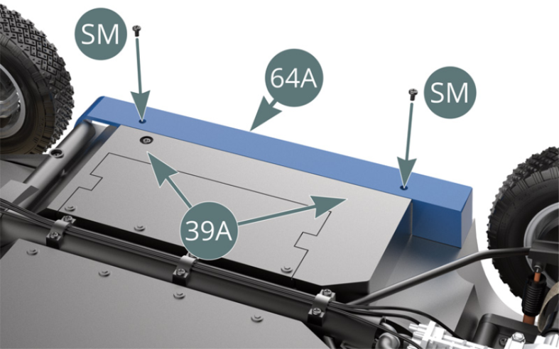
Schéma d’assemblage
Place the rocker panel (64A) onto the chassis floor (39A) and secure it with two SM screws (shown above).

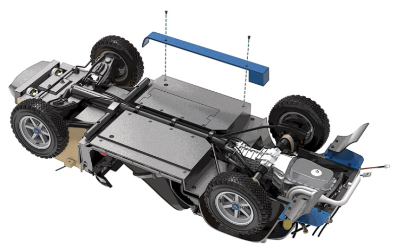
Vue générale