English
 français
 Deutsch
 español
 italiano
 português


Box 20
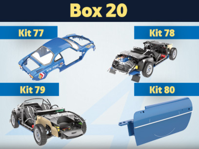
Kit 77 - Assemblage et montage de la trappe, du bouchon et de la niche d’accès du réservoir d’essence
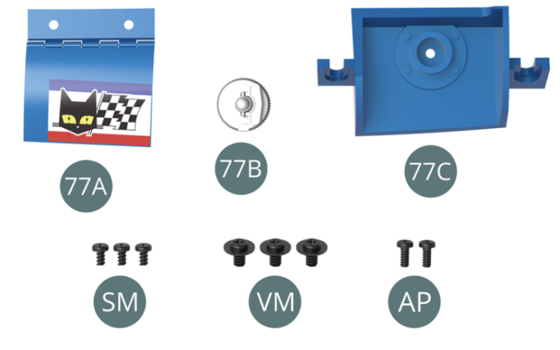
Parts of kit
- 77A Trappe de réservoir d’essence
- 77B Bouchon de réservoir d’essence
- 77C Niche d’accès du réservoir d’essence
- SM Vis M 1,7 x 3 mm (x 3)
- VM Vis M 2,3 x 4 x 6 mm (x 3)
- AP Vis M 1,7 x 4 mm (x 2)
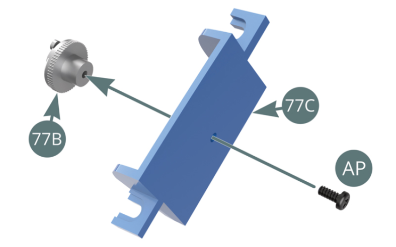
Etape 1
- Screw SM M 1.7 x 3 mm (x 3)
- Screw VM M 2.3 x 4 x 6 mm (x 3)
- Screw AP M 1.7 x 4 mm (x 2)

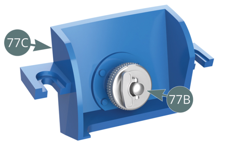
Positionner le bouchon de réservoir 77B sur la niche d’accès 77C et le fixer par derrière avec une vis AP (illustrations ci-contre et ci-dessous).
Etape 2
Position the tank cap (77B) on the access recess (77C) and secure it from the behind with an AP screw (illustrations opposite and below).


Positionner l’attache de la trappe de réservoir d’essence 77A sur le bord supérieur de l’ouverture rectangulaire située sur le côté droit de la carrosserie 66A, puis la fixer de l’intérieur avec deux vis SM.

Etape 3
Position the fuel tank flap (77A) on the top edge of the rectangular opening located on the right side of the bodywork (66A), then secure it from the inside with two SM screws.

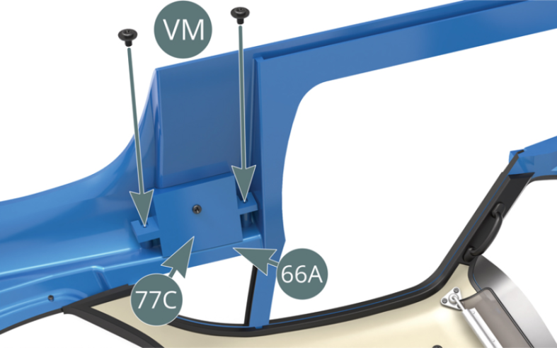
Positionner par au-dessus la niche d’accès du réservoir et la fixer de l’intérieur avec deux vis VM.

Etape 4
Position the tank access niche from above and secure it from the inside with two VM screws.
Vérifier la bonne ouverture et fermeture de la trappe de réservoir d’essence sur le côté extérieur droit de la carrosserie.
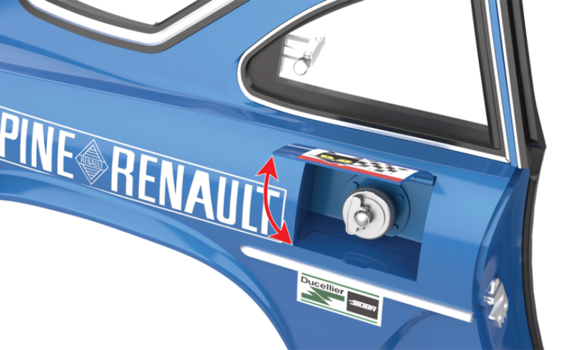
Schéma d’assemblage
Check the correct opening and closing of the fuel tank flap on the right outer side of the bodywork.
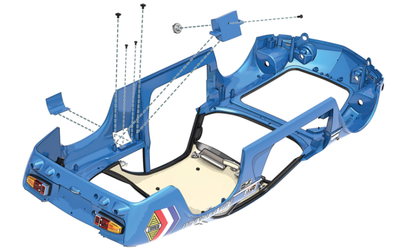
Vue générale
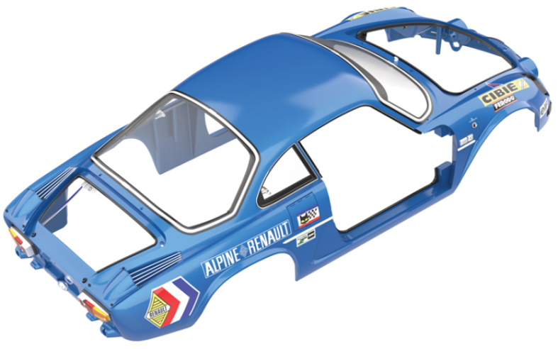
Kit 78 - Assemblage et montage des pare-chocs arrière. Montage des crochets de remorquage et du frein à main
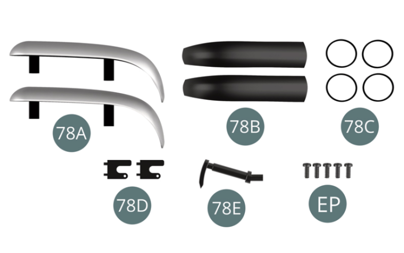
Parts of kit

Etape 1
- 78D Tow hook (x2)
- 78E Handbrake
- Screw EP M 2.0 x 5 mm (x 5)
Positionner les protèges pare-chocs 78B sur les pare-chocs 78A et fixer chacun d’eux avec deux anneaux en caoutchouc 78C.
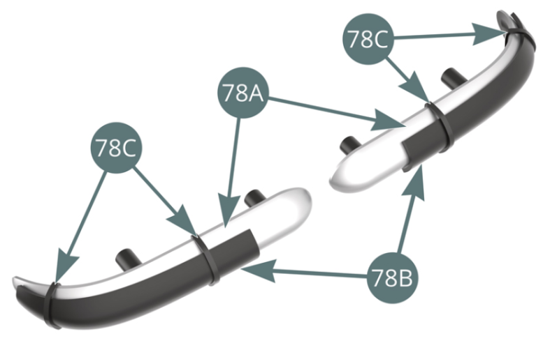
Etape 2
Position the bumper protectors (78B) on the bumpers (78A) and fix each with a rubber rings (78C).

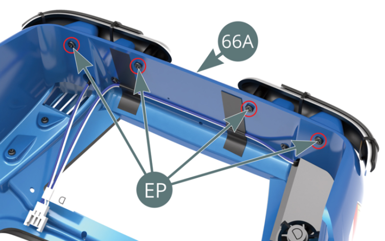
Positionner les deux pare-chocs arrière 78A sur le panneau arrière de la carrosserie 66A et fixer chacun d’eux depuis l’intérieur avec deux vis EP (illustrations ci-contre et ci-dessous).
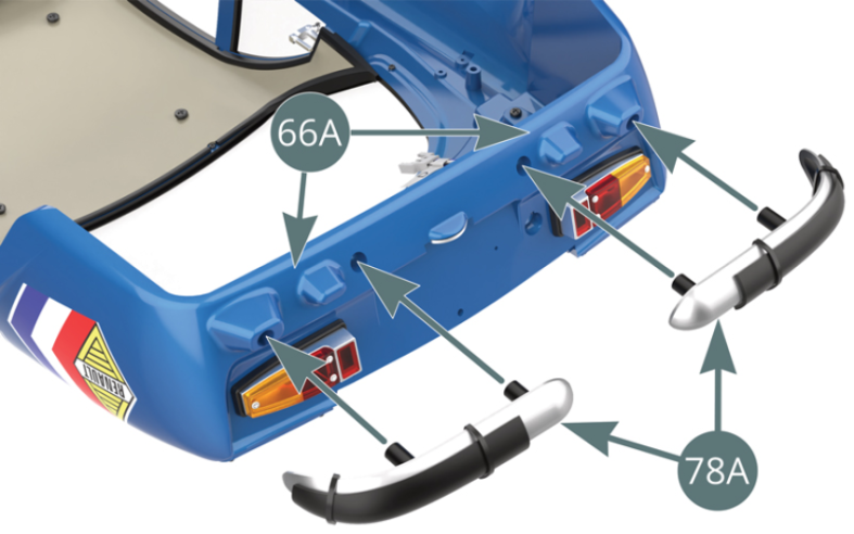

Etape 3
Position the two rear bumpers (78A) on the rear panel of the bodywork (66A) and secure each of them from the inside with two EP screws (illustrations opposite and below).

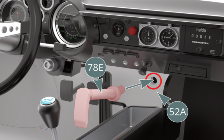
Positionner le frein à main 78E sur le plancher d’habitacle 52A, sous le tableau de bord (illustrations ci-dessus).

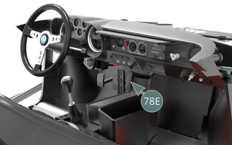
Etape 4
Position the handbrake (78E) on the cabin floor (52A), underneath the dashboard (illustrations above).

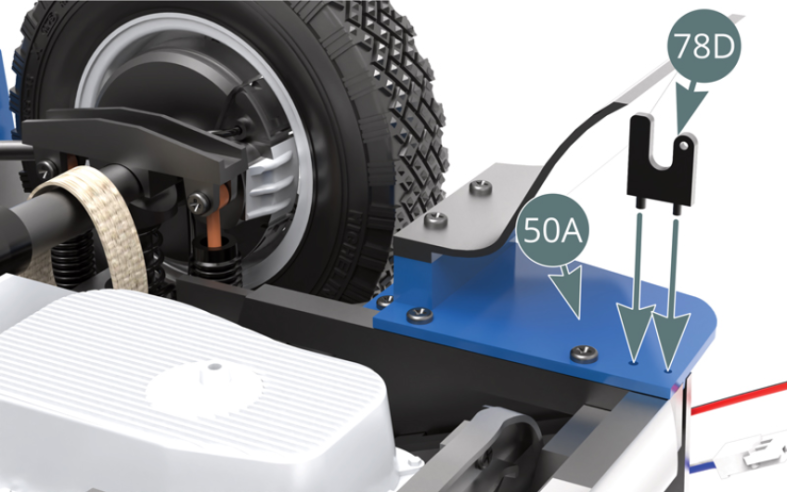
Retourner le châssis et positionner les crochets de remorquage 78D sur les panneaux arrière gauche 50A et arrière droit 50B (illustrations ci-contre et ci-dessous).

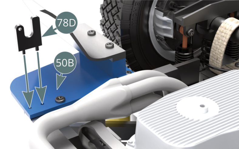
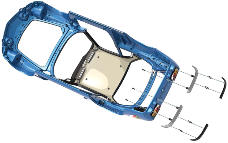
Schéma d’assemblage
Turn the chassis over and position the tow hooks (78D) on the left rear (50A) and right rear (50B) panels (illustrations opposite and below).

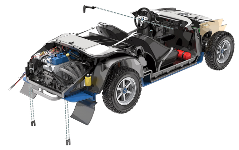
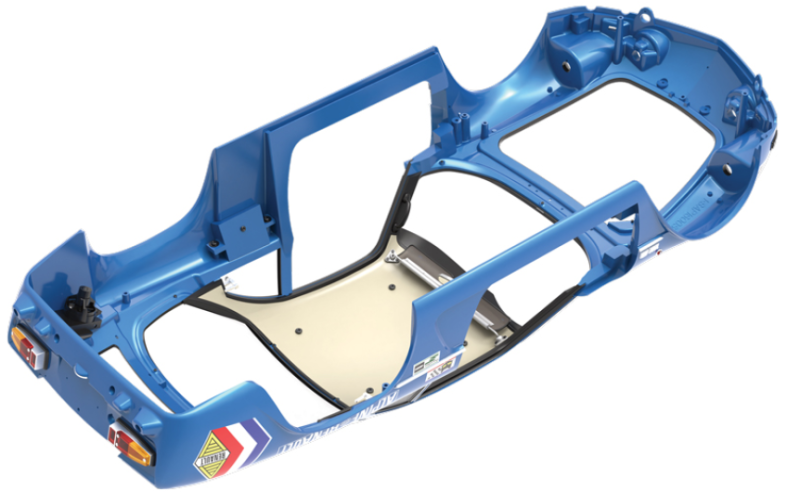
Vue générale

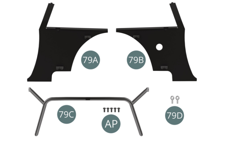
Kit 79 - Montage des panneaux de cockpit latéraux et de l’arceau de sécurité
Parts of kit
Etape 1
- 79D Eye hook (x 2)
- Screw AP M 1.7 x 4 mm (x 5)
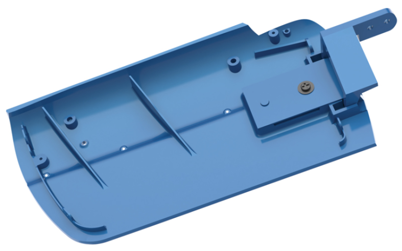
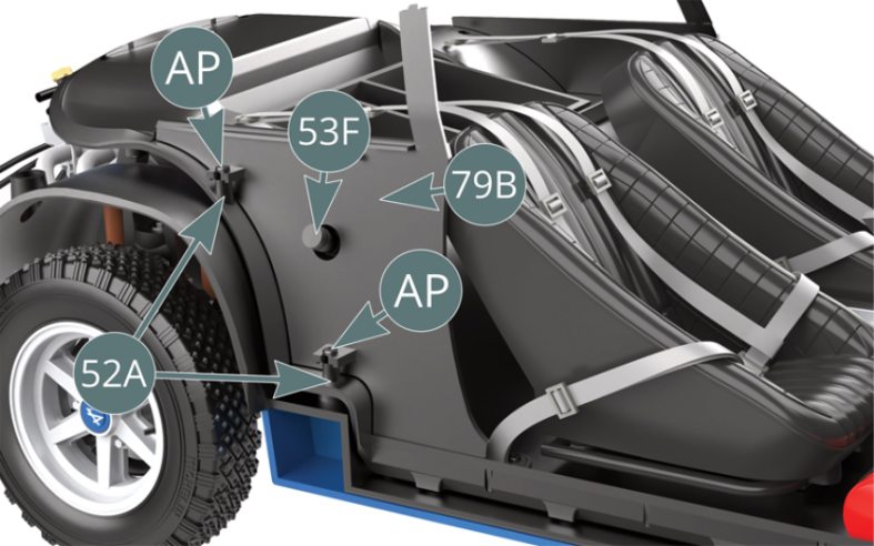
Positionner le panneau de cockpit gauche 79A sur le plancher d’habitacle 52A et le fixer avec deux vis AP.
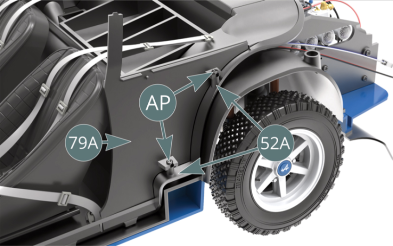
Etape 2
Position the left cabin panel (79A) on the cabin floor (52A) and secure it with two AP screws.

Positionner le panneau de cockpit droit 79B sur le plancher d’habitacle 52A (en faisant passer le goulot de remplissage 53F à travers) et le fixer avec deux vis AP.

Etape 3
Place the right cabin panel (79B) on the cabin floor (52A) (passing the filler neck (53F) through it) and secure it with two AP screws.
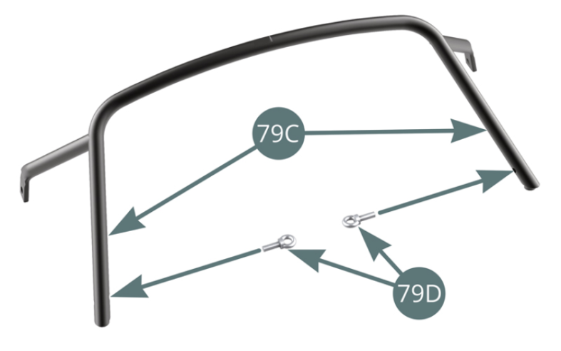
Positionner les deux crochets à œil 79D sur la barre arrière de l’arceau de sécurité 79C.

Etape 4
Position the two eye hooks (79D) on the lower rod of the roll bar (79C).
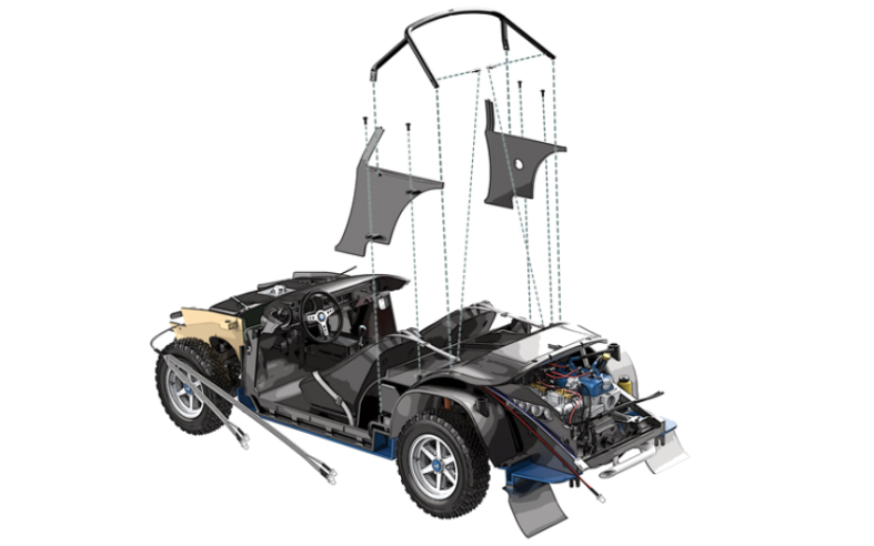
Positionner la barre arrière de l’arceau de sécurité 79C sur le panneau d’habitacle arrière 53C et engager la barre avant dans les logements situés sur le haut des panneaux de cockpit droit 79B et gauche 79A.
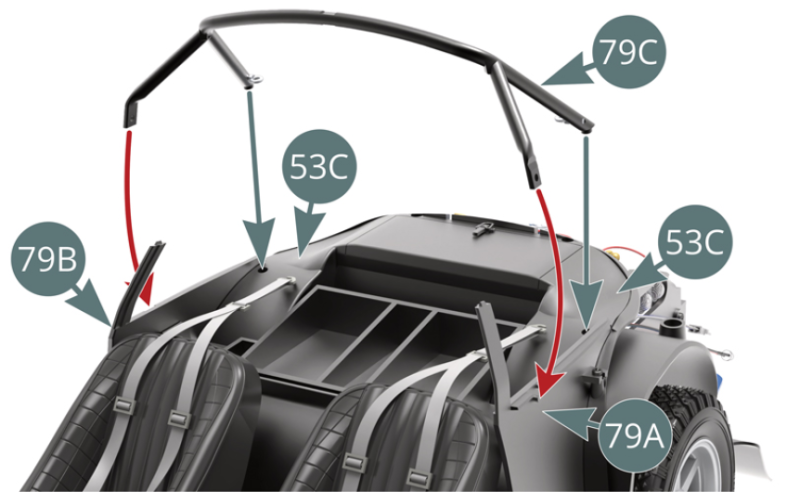
Etape 5
Position the rear rod of the roll bar (79C) on the rear cabin panel (53C) and engage the front rod in the recesses located on the top of the right (79B) and left (79A) cabin panels.
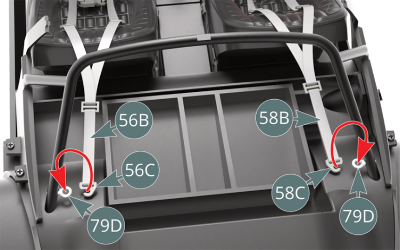
Attacher les ceintures de sécurité 58B et 56B à l’aide de leurs boucles à crochet respectives 58C et 56C sur les crochets à œil 79D situés de chaque côté de l’arceau de sécurité (illustrations ci-dessus et ci-dessous).
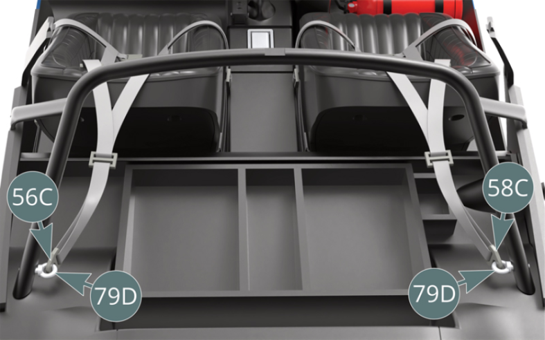
Schéma d’assemblage
Attach the seat belts (58B&56B) - using their respective hook buckles (58C&56C) - to the eye hooks (79D) located on each side of the roll bar (illustrations above and below).
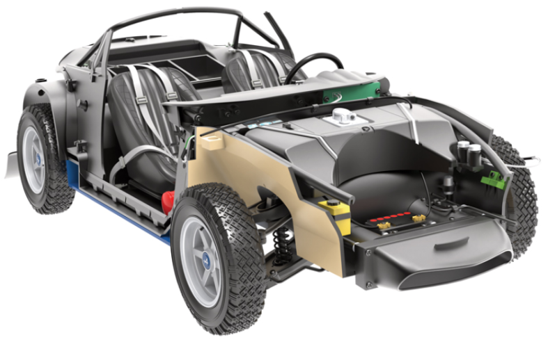
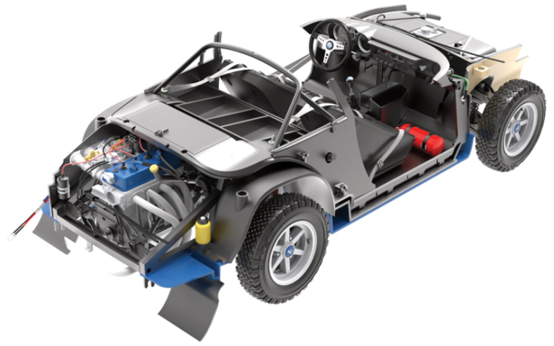
Vue générale
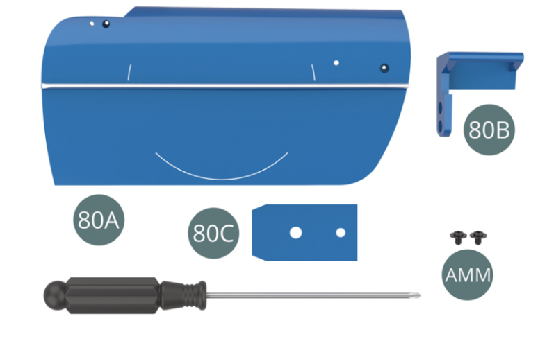
Kit 80 - Assemblage de la portière gauche
Parts of kit

Etape 1
- 80C Leaf spring
- Screw AMM M 2.3 x 3 x 6 mm (x 2)
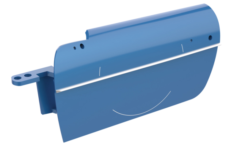
Positionner l’axe de la charnière 80B dans le logement prévu sur le côté intérieur de la portière gauche 80A.
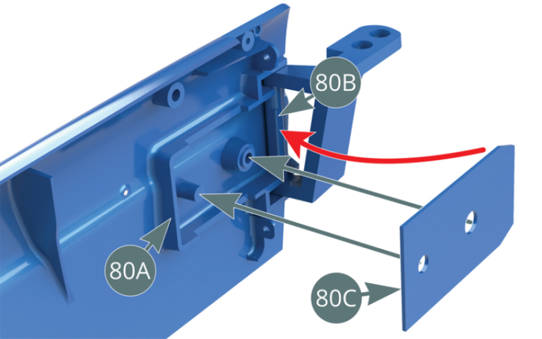
Positionner l’extrémité conique du ressort à lame 80C le long de l’axe de la charnière 80B, puis positionner les deux trous du ressort dans les tétons situés sur le côté intérieur de la portière gauche 80A.
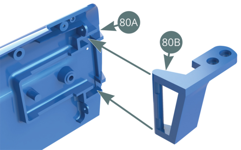

Etape 2
Position the hinge axis (80B) in the housing provided on the inside of the left door (80A). Position the tapered end of the leaf spring (80C) alongside the hinge axis (80B), then position the two openings of the spring into the protrusions located on the inside of the left door (80A).

Fixer le ressort à lame 80C sur la portière gauche 80A avec une vis AMM.
Ne pas trop serrer la vis afin de permettre le mouvement rotatif de la charnière 80B.
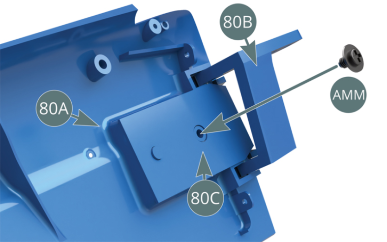
Schéma d’assemblage
Secure the leaf spring (80C) to the left door (80A) with an AMM screw. Do not overtighten the screw in order to allow the rotation of the hinge (80B).

Vue générale