English
 français
 Deutsch
 español
 italiano
 português


Box 24
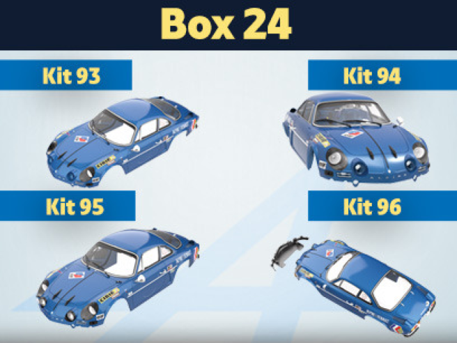
Kit 93 - Assemblage et montage du phare gauche
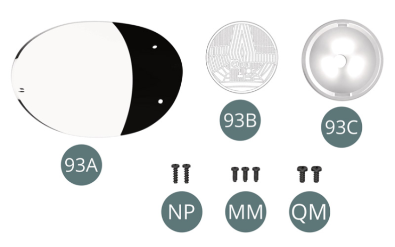
Parts of kit
- 93A Bulle de phare gauche
- 93B Lentille de phare gauche
- 93C Boîtier de phare gauche
- NP Vis M 1,2 x 4 mm (x 2)
- MM Vis M 1,2 x 3 mm (x 3)
- QM Vis M 1,4 x 3 mm (x 2)
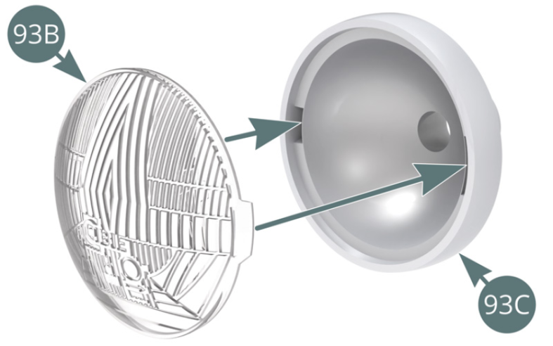
Etape 1
- Screw NP M 1.2 x 4 mm (x 2)
- Screw MM M 1.2 x 3 mm (x 3)
- Screw QM M 1.4 x 3 mm (x 2)

Positionner la lentille de phare gauche 93B sur le boîtier de phare gauche 93C.

Etape 2
Place the left headlight lens (93B) on the left headlight housing (93C).
Positionner le boîtier de phare gauche 93C sur la carrosserie 66A.
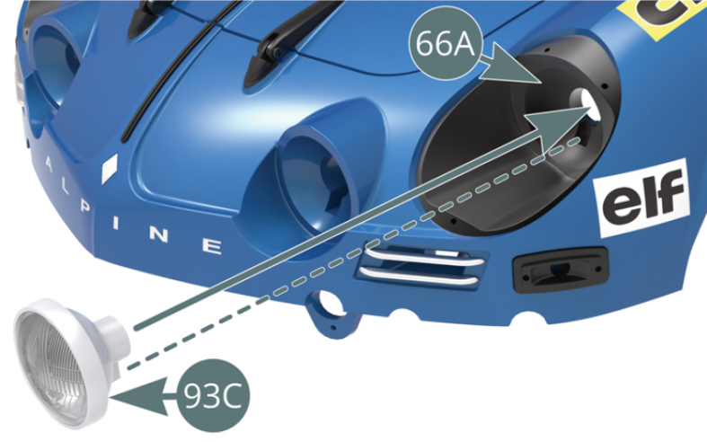
Etape 3
Position the left headlamp housing (93C) on the body (66A).

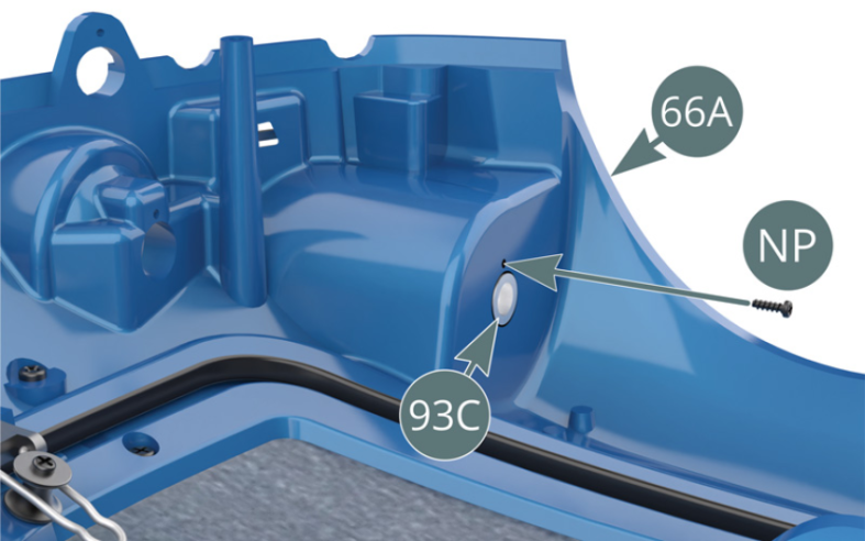
Fixer le boîtier de phare gauche 93C par l’arrière sur la carrosserie 66A avec une vis NP.

Etape 4
Secure the housing of the left headlamp (93C), from the rear, to the body (66A) using an NP screw.
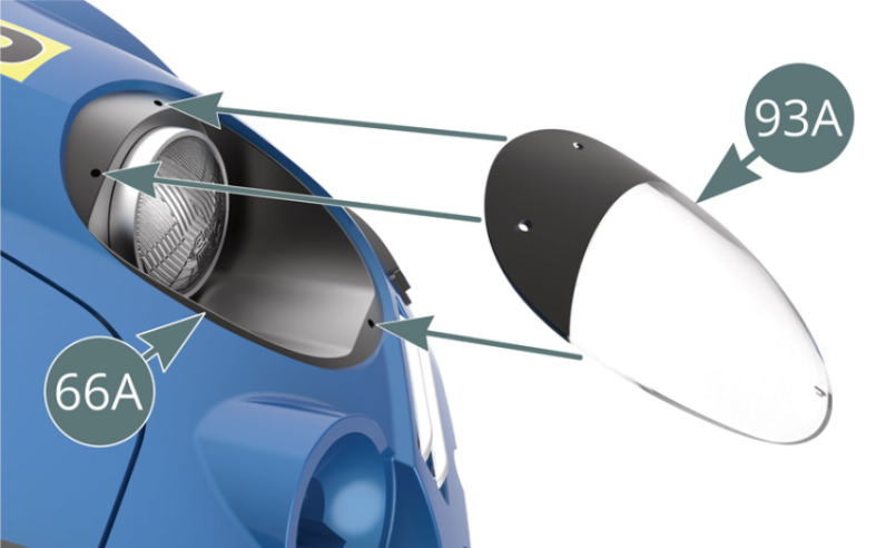
Positionner la bulle de phare gauche 93A sur la carrosserie 66A.

Etape 5
Position the fairing of the left headlight (93A) on the body (66A).
Fixer le bas de la bulle de phare gauche 93A sur la carrosserie 66A avec une vis QM. Veiller à ne pas trop la serrer afin de ne pas fendre la bulle de phare.
Fixer le haut de la bulle de phare gauche 93A sur la carrosserie 66A avec deux vis MM. Veiller à ne pas trop les serrer afin de ne pas fendre la bulle de phare.
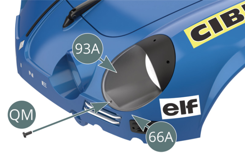

Schéma d’assemblage
Affix the bottom of the fairing of the left headlight (93A) to the body (66A) using a QM screw. Be careful not to overtighten the screw, as this will split the headlight fairing. Fix the top of the left headlamp fairing (93A) to the body (66A) using two MM screws, making sure not to overtighten them to avoid splitting the headlamp bubble.

Vue générale


Kit 94 - Assemblage et montage du phare droit
Parts of kit

Etape 1
- Screw NP M 1.2 x 4 mm (x 2)
- Screw MM M 1.2 x 3 mm (x 3)
- Screw QM M 1.4 x 3 mm (x 2)

Positionner la lentille de phare droit 94B sur le boîtier de phare droit 94C.

Etape 2
Place the right headlight lens (94B) on the right headlight housing (94C).

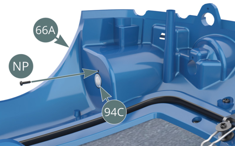
Positionner le boîtier de phare droit 94C sur la carrosserie 66A.
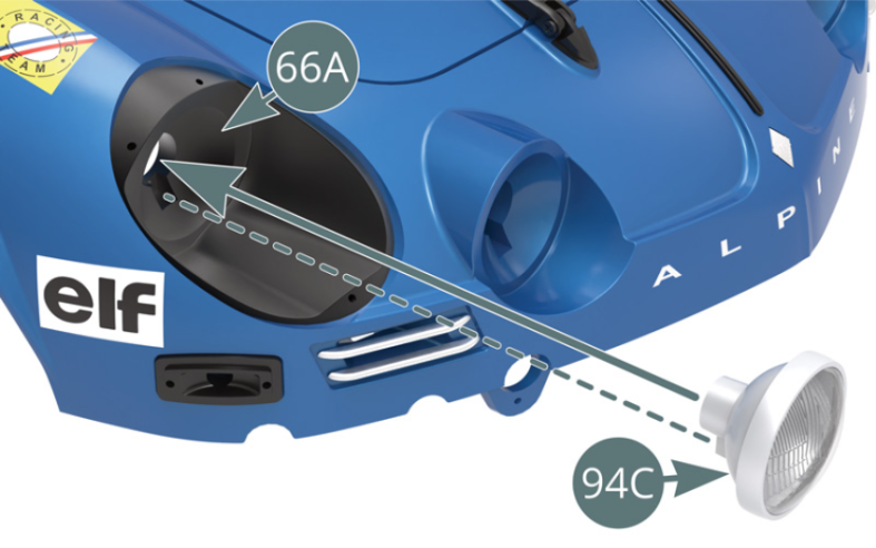
Etape 3
Position the right headlamp housing (94C) on the body (66A).

Fixer le boîtier de phare droit 94C par l’arrière sur la carrosserie 66A avec une vis NP.
Etape 4
Secure the housing of the right headlamp (94C), from the rear, to the body (66A) using an NP screw.

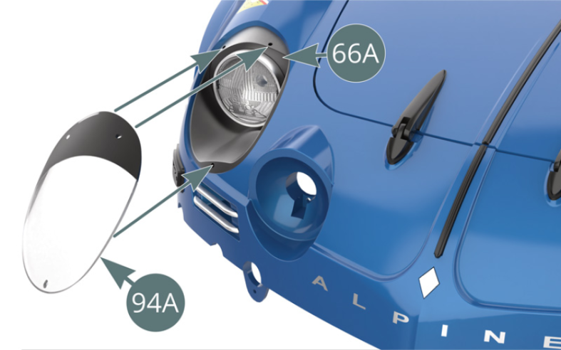
Positionner la bulle de phare droit 94A sur la carrosserie 66A.
Etape 5
Position the fairing of the right headlight (94A) on the body (66A).

Fixer le bas de la bulle de phare droit 94A sur la carrosserie 66A avec une vis QM. Veiller à ne pas trop la serrer afin de ne pas fendre la bulle de phare.
Fixer le haut de la bulle de phare gauche 94A sur la carrosserie 66A avec deux vis MM. Veiller à ne pas trop les serrer afin de ne pas fendre la bulle de phare.
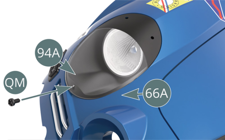
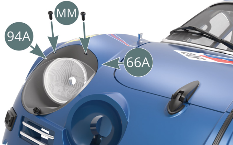
Schéma d’assemblage
Affix the bottom of the fairing of the right headlight (94A) to the body (66A) using a QM screw. Be careful not to overtighten the screw, as this will split the headlight fairing. Fix the top of the right headlamp fairing (94A) to the body (66A) using two MM screws, making sure not to overtighten them to avoid splitting the headlamp fairing.

Vue générale


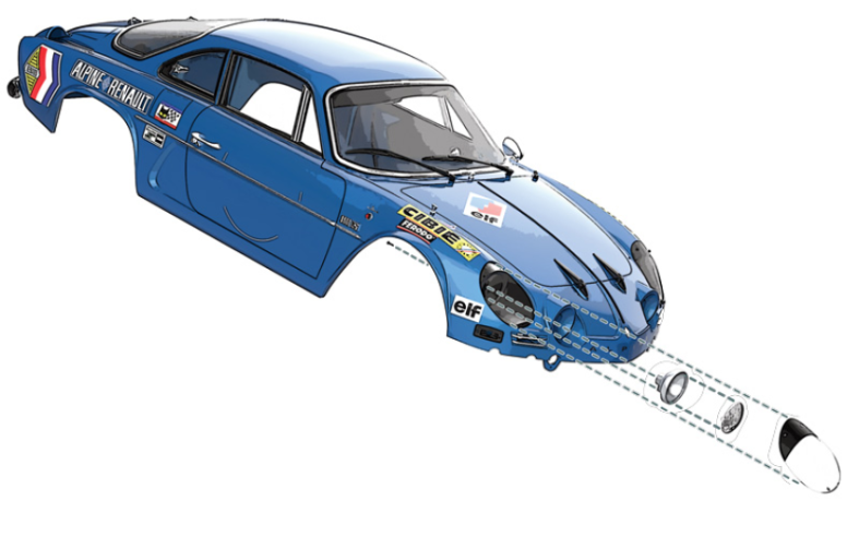
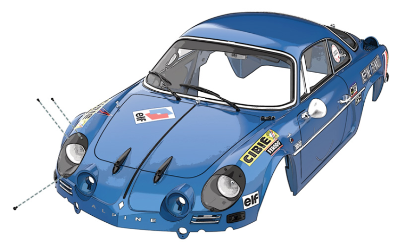
Kit 95 - Montage des phares longue portée
Parts of kit

Etape 1
- 95D Decal, right long-range headlight
- Screw NP M 1.2 x 4 mm (x 3)
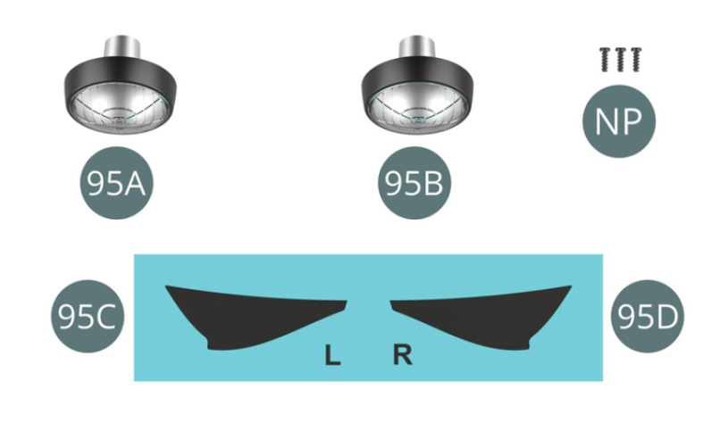
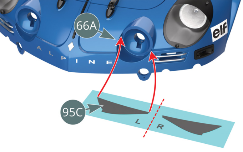
Découpez la décalcomanie du phare longue portée gauche 95C.
La plonger dans l’eau pendant 30 secondes, puis la faire glisser dans le logement prévu pour le phare longue portée gauche sur la carrosserie 66A.
Enlever l’excès d’eau avec un coton et laisser sécher pendant 5 minutes.
Etape 2
First, cut out the decal for the left long-range headlamp (95C). Soak it in water for 30 seconds, then place it in the recess provided for the left long-range headlamp on the body (66A). Remove excess water with a cotton pad and leave to dry for 5 minutes.

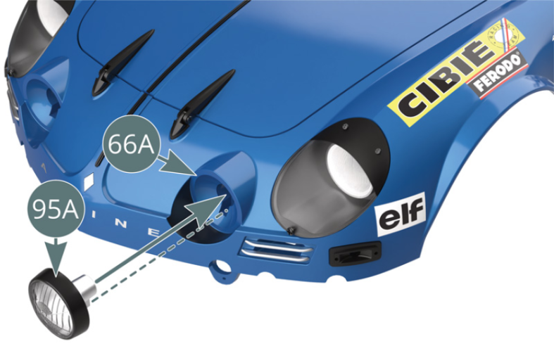
Positionner le phare longue portée gauche 95A dans le logement prévu sur la carrosserie 66A.
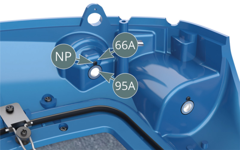
Fixer le phare longue portée 95A par l’arrière sur la carrosserie 66A avec une vis NP.

Etape 3
Position the left long-range headlamp (95A) in the housing provided on the body (66A). Secure the long-range headlamp (95A) from behind to the body (66A) using an NP screw.

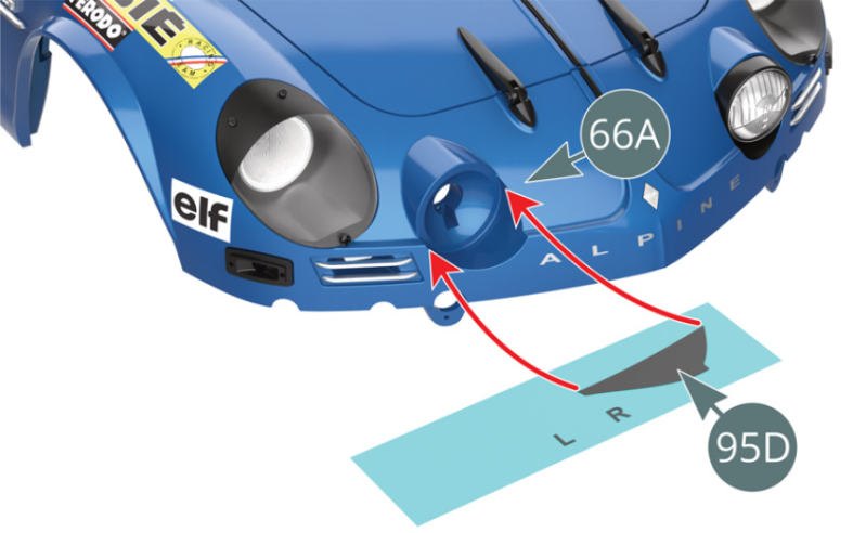
Découpez la décalcomanie du phare longue portée droit 95D.
La plonger dans l’eau pendant 30 secondes, puis la faire glisser dans le logement prévu pour le phare longue portée droit sur la carrosserie 66A.
Enlever l’excès d’eau avec un coton et laisser sécher pendant 5 minutes.

Etape 4
First, cut out the decal for the right long-range headlamp (95D). Soak it in water for 30 seconds, then place it in the recess provided for the right long-range headlamp on the body (66A). Remove excess water with a cotton pad and leave to dry for 5 minutes.
Positionner le phare longue portée droit 95B dans le logement prévu sur la carrosserie 66A.
Fixer le phare longue portée droit 95B par l’arrière sur la carrosserie 66A avec une vis NP.
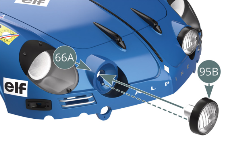
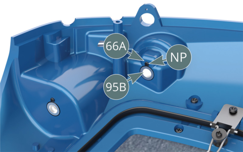
Schéma d’assemblage
Position the right long-range headlamp (95B) in the housing provided on the body (66A). Secure the long-range headlamp (95B) from behind to the body (66A) using an NP screw.

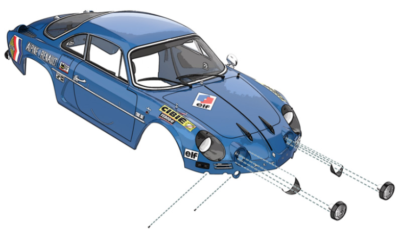
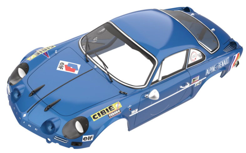
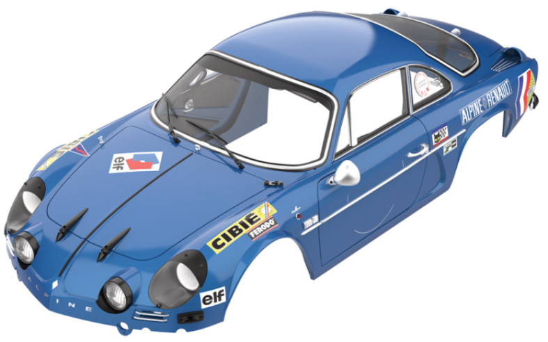
Vue générale

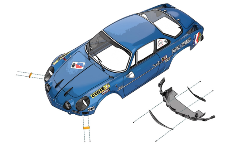
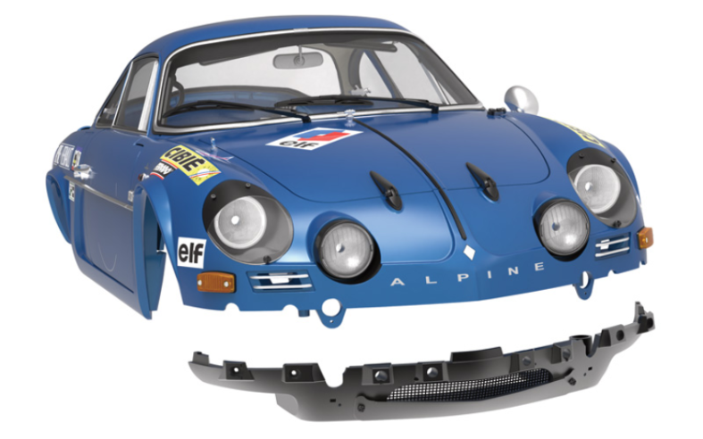
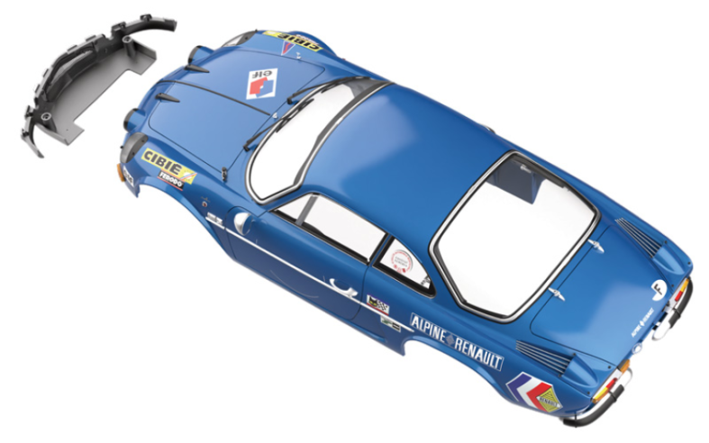
Kit 96 - Assemblage du bas de caisse avant, montage des clignotants et de l’extension de câble
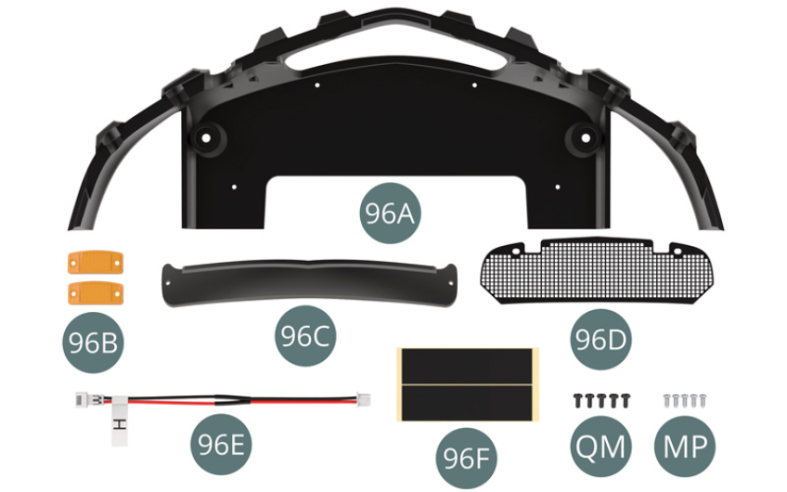
Parts of kit

Etape 1
- 96E Cable extension H
- 96F Adhesive tape (x2)
- Screw QM M 1.4 x 3 mm (x 5)
- Screw MP M 1.2 x 3 mm (x 5)
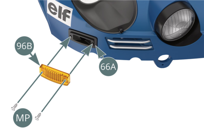
Positionner le cabochon de clignotant 96B sur le logement prévu à l’avant droit de la carrosserie 66A et le fixer avec deux vis MP.
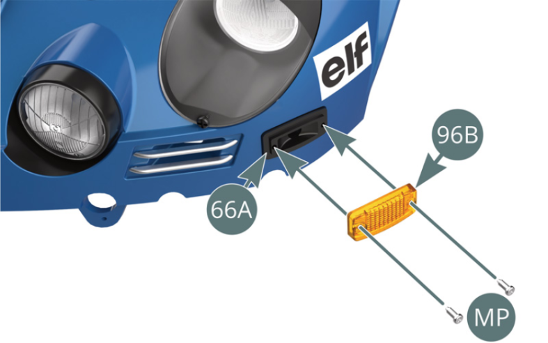
Positionner le cabochon de clignotant 96B sur le logement prévu à l’avant gauche de la carrosserie 66A et le fixer avec deux vis MP.


Etape 2
Position the blinker cap (96B) in the housing on the right front of the body (66A) and secure with two MP screws.
Position the blinker cap (96B) in the housing on the front left of the body (66A) and secure it with two MP screws.
Positionner le protège-grille 96C sur le bas de caisse avant 96A et le fixer avec deux vis QM.
Plier la grille 96D pour l’adapter à la courbure de la paroi intérieure du bas de caisse avant 96A.
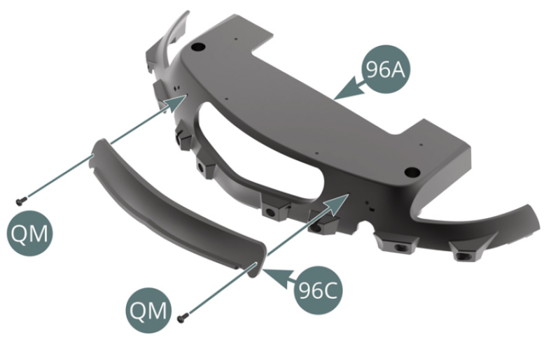

Etape 3
Position the grille protector (96C) on the front rocker panel (96A) and secure with two QM screws. Bend the grille (96D) to match the curve of the inner wall of the front rocker panel (96A).


Fixer la grille 96D sur la paroi intérieure du bas de caisse avant 96A avec deux vis QM.
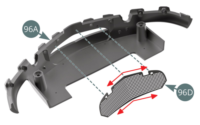
Schéma d’assemblage
Fix the grille (96D) to the inner wall of the front rocker panel (96A) using two QM screws.
Vue générale


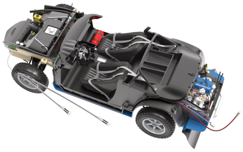
NOS CONSEILS POUR FACILITER LE MONTAGE
Etape 1
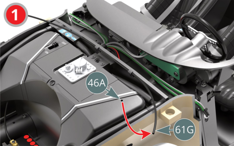
Commencer par retirer la conduite d’essence 61G du réservoir d’essence 46A.
Etape 2
Start by removing the fuel line (61G) from the fuel tank (46A).

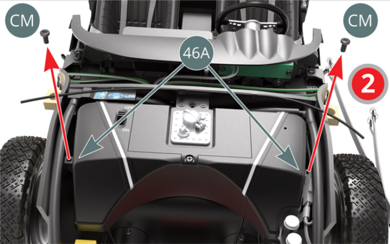
Dévisser, retirer et mettre de côté pour plus tard les deux vis CM situées sur les pattes latérales du réservoir d’essence 46A.
Etape 3
Release, remove and set aside for use at a later stage the two CM screws located on the side tabs of the fuel tank (46A).

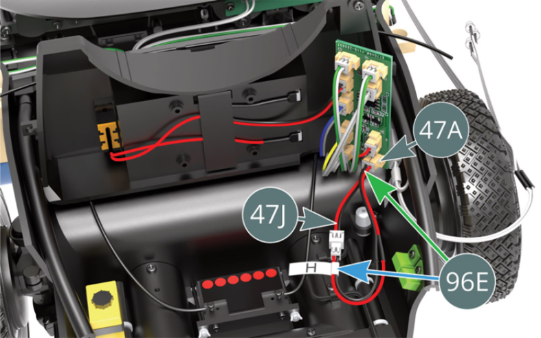
Détacher le ruban adhésif 47B du circuit imprimé 47A et retirer celui-ci.
Repérer la prise marquée H sur le circuit imprimé 47A et débrancher le câble H 47J (rouge-noir).
Brancher l’une des extrémités de l’extension de câble H 96E sur le câble H 47J précédemment débranché, puis l’autre extrémité sur le circuit imprimé 47A.
Remonter le circuit imprimé 47A et le réservoir d’essence 46A en suivant en sens inverse les instructions 3 et 2 indiquées par une flèche rouge.
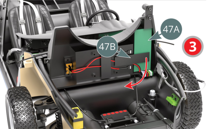
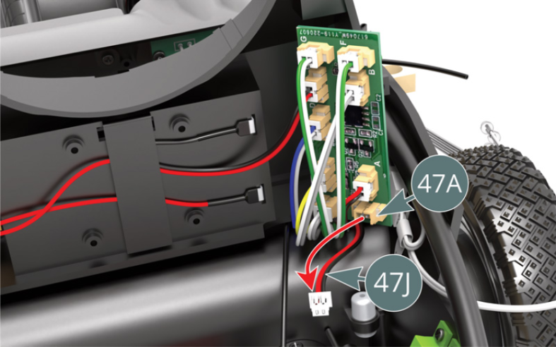
Peel off the adhesive tape (47B) from the PCB (47A). Identify the connector marked H on the circuit board (47A) and disconnect cable H (47J) (red-black). Connect one end of cable extension H (96E) to the previously disconnected cable H (47J), then the other end to the PCB (47A). Reassemble the PCB (47A) and fuel tank (46A), following instructions 3 and 2 in reverse order, indicated by a red arrow.
Etape 4


Retirer l’écusson de volant 67C en faisant levier puis dévisser et mettre de côté pour plus tard la vis AM. Retirer le volant 67B (ou 3K) et veiller à maintenir les roues avant bien droites.
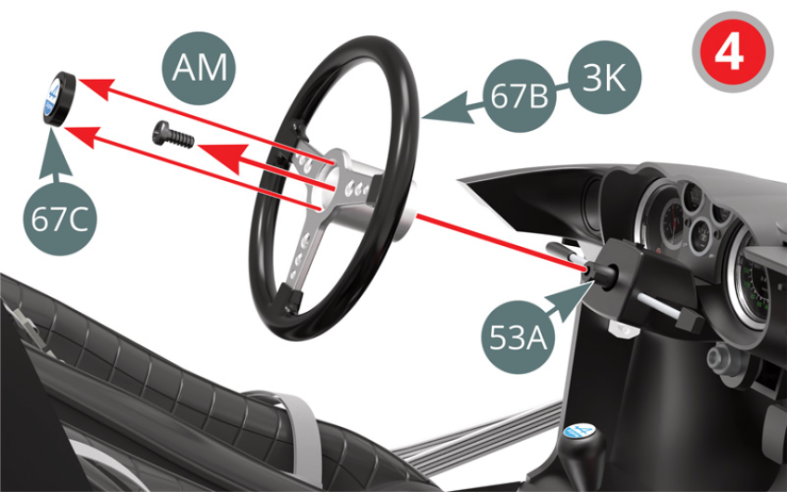
Etape 5
Remove the steering wheel emblem (67C) by applying some pressure, then unscrew the AM screw and put it aside for later use. Remove the steering wheel (67B or 3K) and keep the front wheels straight.

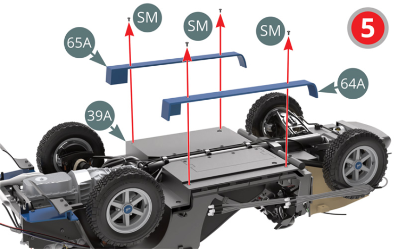
Retourner le châssis et dévisser les quatre vis SM (les conserver pour plus tard), puis retirer les bas de caisse gauche 64A et droit 65A.

Etape 6
Turn the chassis over and unscrew the four SM screws ( save them to use at a later date), then remove the left (64A) and right (65A) rocker panels.
Commencer par retirer la conduite d’essence 61G du réservoir d’essence 46A.
Etape 7
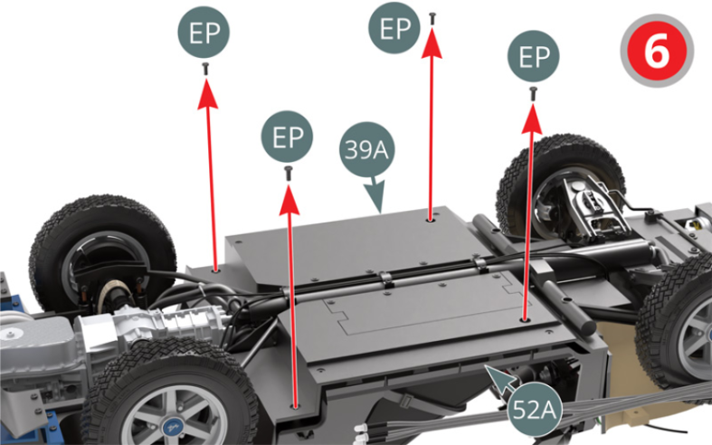
Unscrew and save the four EP screws, then detach the cabin floor (52A) from the chassis floor (39A).

Soulever, reculer et incliner le plancher de châssis 39A afin d’accéder aux deux rubans adhésifs 57F qui maintiennent le câble H 47J (rouge-noir), puis les retirer.
Tirer délicatement vers l’arrière le câble H 47J (rouge- noir) afin de le tendre au maximum.
Remonter le châssis, le plancher d’habitacle et le volant en suivant en sens inverse les instructions 7, 6, 5, 4 et 1 indiquées par une flèche rouge. Utiliser du ruban adhésif 96F si nécessaire.
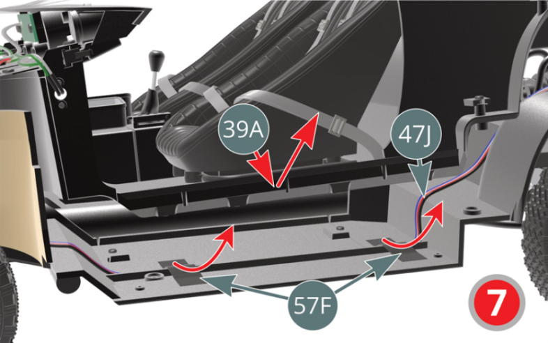

Vue générale
Lift, retract and tilt the chassis floor (39A) to access and remove the two adhesive tapes (57F) holding the cable H (47J) (red-black). Gently pull back the cable H (47J) (red/black) so as to tension it as much as possible. Refit the chassis, cabin floor and steering wheel, following instructions 7, 6, 5, 4 and 1 in reverse order, indicated by a red arrow. Use adhesive tape (96F) if necessary.