English
 français
 Deutsch
 español
 italiano
 português


Box 25
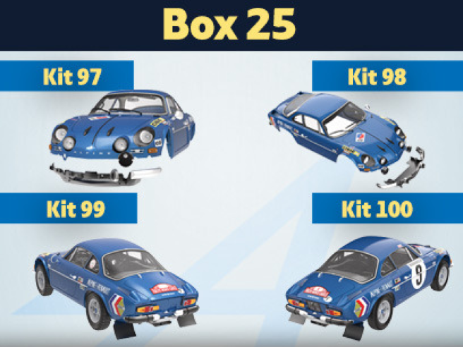
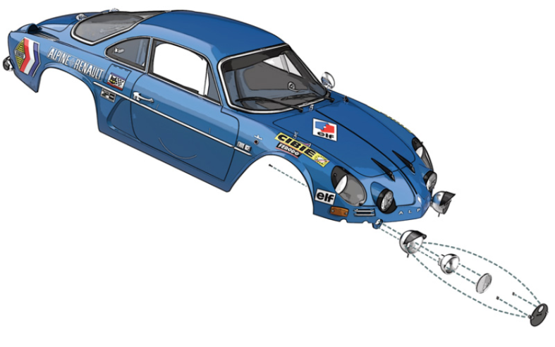
Kit 97 - Assemblage et montage du phare antibrouillard gauche
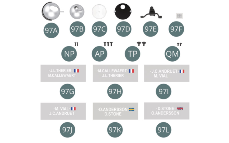
Parts of kit
- 97A Boîtier de phare antibrouillard gauche
- 97B Réflecteur
- 97C Lentille de phare
- 97D Cache avec guide faisceau
- 97E Support de phare
- antibrouillard gauche
- 97F Ruban adhésif double face (x 4)
- 97G Autocollant gauche «noms des pilotes» voiture n° 9 (x 2)
- 97H Autocollant droit «noms des pilotes» voiture n° 9 (x 2)
- 97I Autocollant gauche «noms des pilotes» voiture n° 22 (x 2)
- 97J Autocollant droit «noms des pilotes» voiture n° 22 (x 2)
- 97K Autocollant gauche «noms des pilotes» voiture n° 28 (x 2)
- 97L Autocollant droit «noms des pilotes» voiture n° 28 (x 2)
- NP Vis M 1,2 x 4 mm (x 2)
- AP Vis M 1,7 x 4 mm (x 3)
- TP Vis M 1,7 x 4 x 5,5 mm (x 2)
- QM Vis M 1,4 x 3 mm (x 2)

Etape 1
- 97I Sticker Left "driver's names" car #22 (x 2)
- 97J Sticker Right "drivers' names" car #22 (x 2)
- 97K Sticker Left "driver's names" car #28 (x 2)
- 97L Sticker Right "Drivers' names" #28 (x 2)
- Screw NP M 1.2 x 4 mm (x 2)
- Screw AP M 1.7 x 4 mm (x 3)
- Screw TP M 1.7 x 4 x 5.5 mm (x 2)
- Screw QM M 1.4 x 3 mm (x 2)
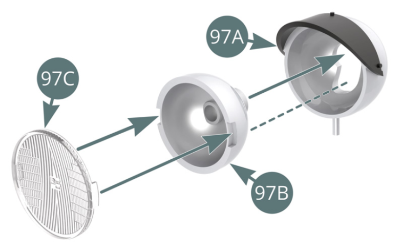
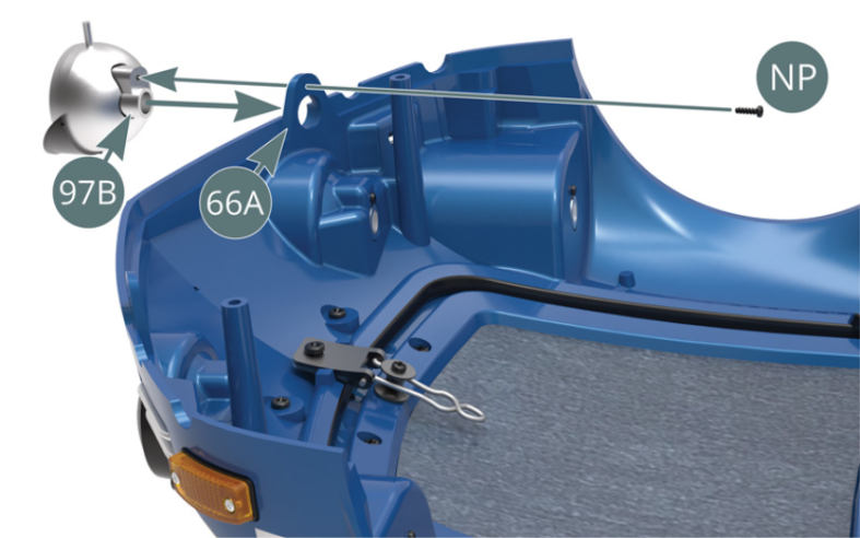
Positionner la lentille de phare 97C sur le réflecteur 97B et placer celui-ci dans le boîtier de phare antibrouillard gauche 97A. Retourner la carrosserie 66A, positionner le phare antibrouillard et le fixer par le réflecteur 97B avec une vis NP.


Etape 2
Position the headlight lens (97C) on the reflector (97B) and fit the reflector into the left fog light housing (97A). Turn the body (66A) over, place the fog light into position and secure with an NP screw through the reflector (97B).
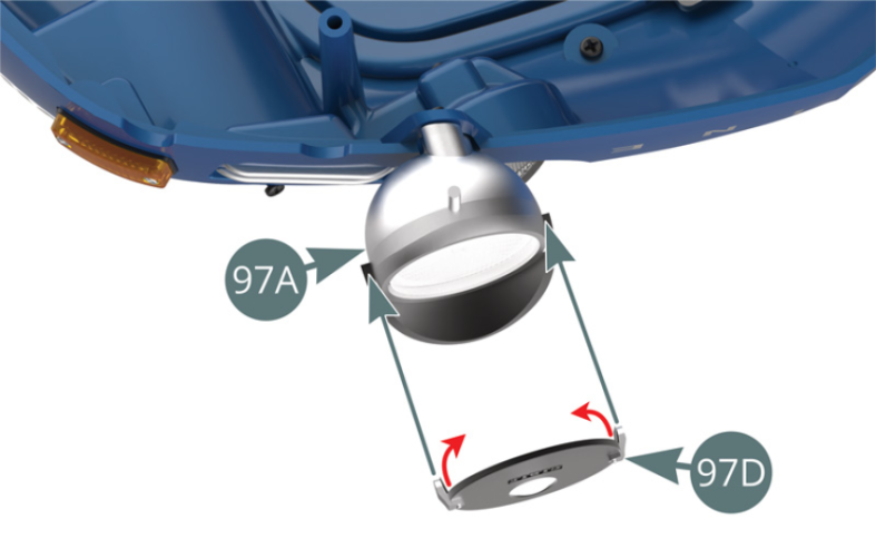
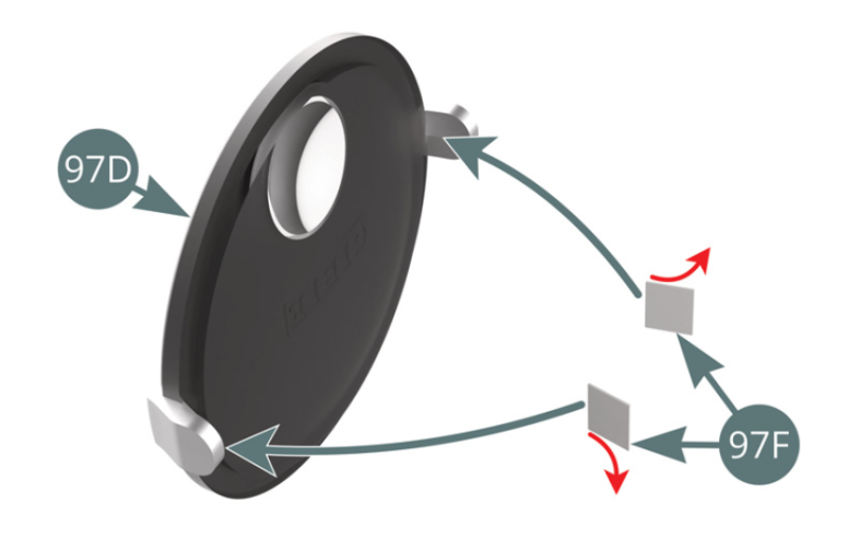
Détacher le support papier (d’un seul côté) de deux rubans adhésifs double-face 97F et les fixer à l’intérieur des pattes du cache 97D. Détacher l’autre support papier des deux rubans adhésifs (flèches rouges) et fixer le cache 97D sur le boîtier de phare antibrouillard gauche 97A (illustrations ci-dessus).

Etape 3
Remove the paper backing (on one side only) from two double-sided adhesive tapes (97F) and attach them to the inside of the covers (97D). Then remove the backing paper of the other side of the two adhesive tapes (red arrows) and attach the cover (97D) to the left fog light housing (97A) (illustrations above).

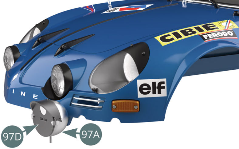
Le cache avec guide faisceau 97D est fixé sur le boîtier de phare antibrouillard gauche 97A.

Etape 4
The cover with beam guide (97D) is attached to the left fog light housing (97A).
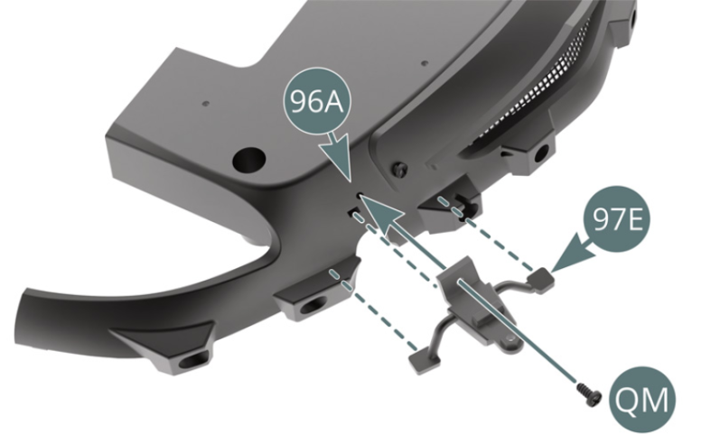
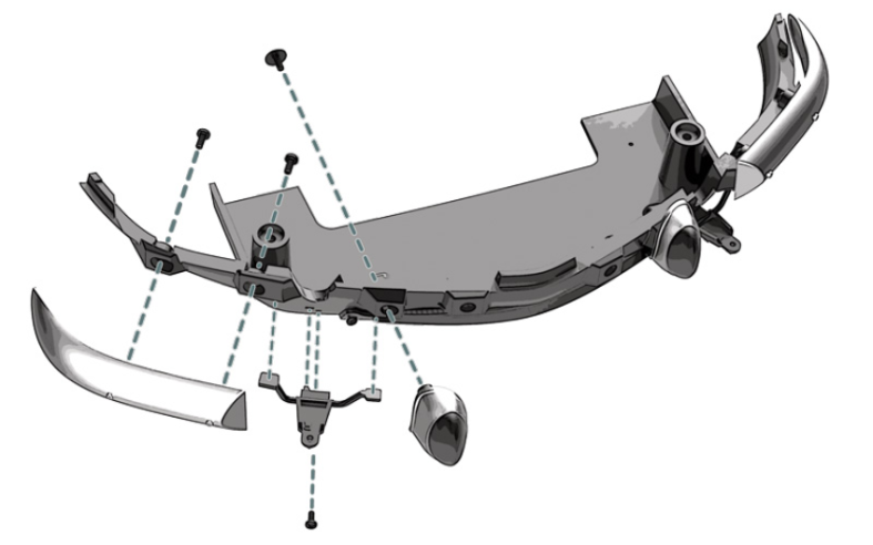
Positionner le support de phare antibrouillard gauche 97E sur le côté gauche du bas de caisse avant 96A et le fixer avec une vis QM.

Etape 5
Position the left fog light bracket (97E) on the left side of the front rocker panel (96A) and secure it with a QM screw.
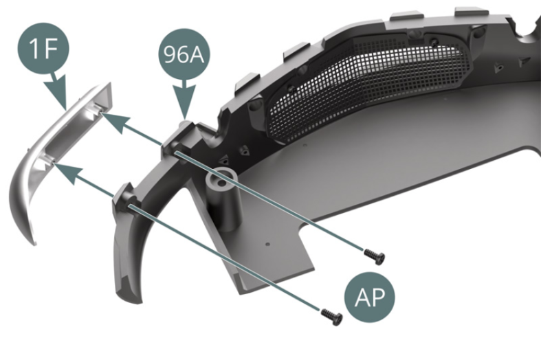
Positionner le pare-chocs avant gauche 1F sur le bas de caisse avant 96A et le fixer avec deux vis AP.
Positionner le caoutchouc de butoir de pare-chocs gauche 1H sur le bas de caisse avant 96A et le fixer avec une vis TP.

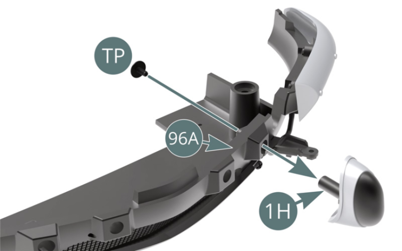
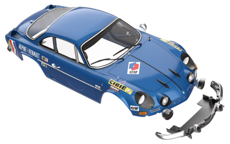
Schéma d’assemblage
Place the left front bumper (1F) on the front rocker panel (96A) and secure it with two AP screws. Position the left bumper rubber (1H) on the front rocker panel (96A) and secure it with a TP screw.
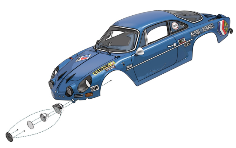
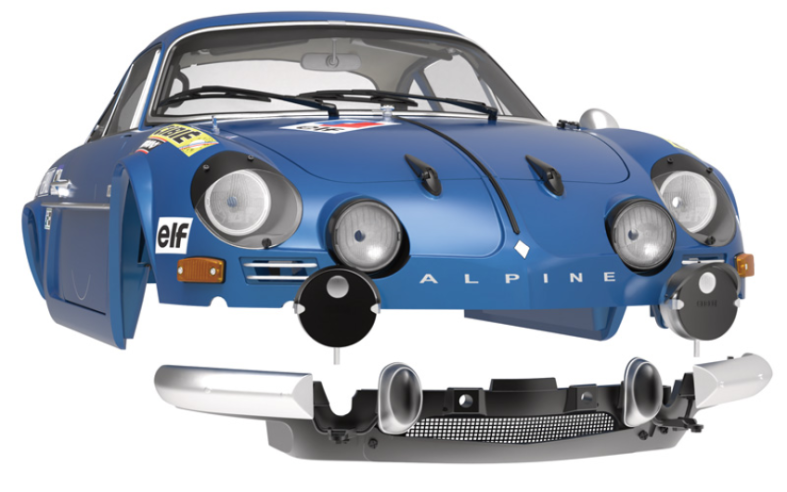
Vue générale

Kit 98 - Assemblage et montage du phare antibrouillard droit
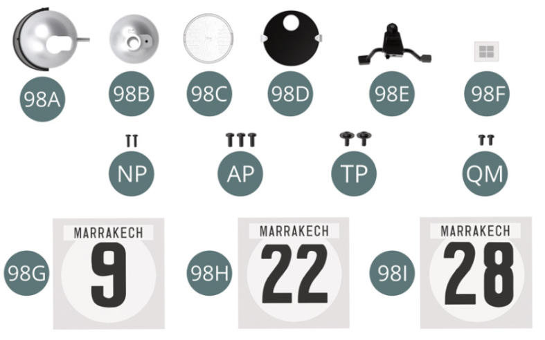
Parts of kit

Etape 1
- 98H Sticker Car door car #22 (x 4)
- 98I Sticker Car door car #28 (x 4)
- Screw NP M 1.2 x 4 mm (x 2)
- Screw AP M 1.7 x 4 mm (x 3)
- Screw TP M 1.7 x 4 x 5.5 mm (x 2)
- Screw QM M 1.4 x 3 mm (x 2)
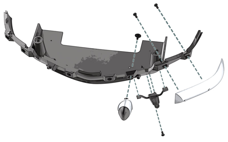
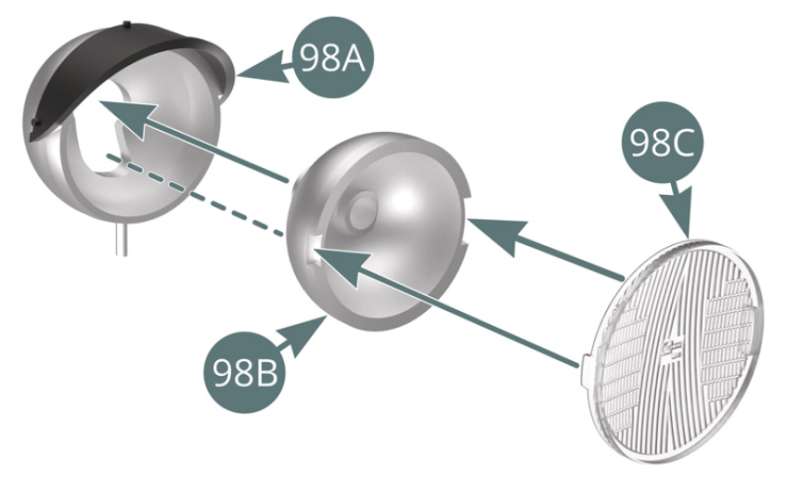
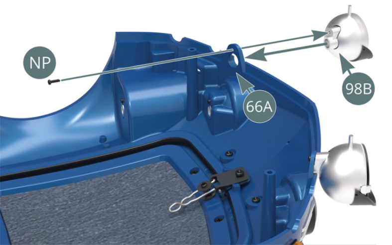
Positionner la lentille de phare 98C sur le réflecteur 98B et placer celui-ci dans le boîtier de phare antibrouillard droit 98A. Retourner la carrosserie 66A, positionner le phare antibrouillard et le fixer par le réflecteur 98B avec une vis NP.


Etape 2
Position the headlight lens (98C) on the reflector (97B) and fit the reflector into the right fog light housing (98A). Turn the body (66A) over, place the fog light into position and secure with an NP screw through the reflector (98B).
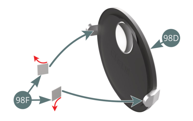
Détacher le support papier (d’un seul côté) de deux rubans adhésifs double face 98F et les fixer à l’intérieur des pattes du cache 98D. Détacher l’autre support papier des deux rubans adhésifs (flèches rouges) et fixer le cache 98D sur le boîtier de phare antibrouillard droit 98A (illustrations ci-dessus).

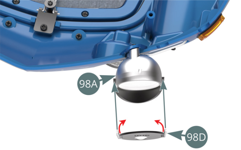
Etape 3
Remove the paper backing (on one side only) from two double-sided adhesive tapes (98F) and attach them to the inside of the covers (98D). Then remove the backing paper of the other side of the two adhesive tapes (red arrows) and attach the cover (98D) to the left fog light housing (98A) (illustrations above).

Le cache avec guide faisceau 98D est fixé sur le boîtier de phare antibrouillard droit 98A.
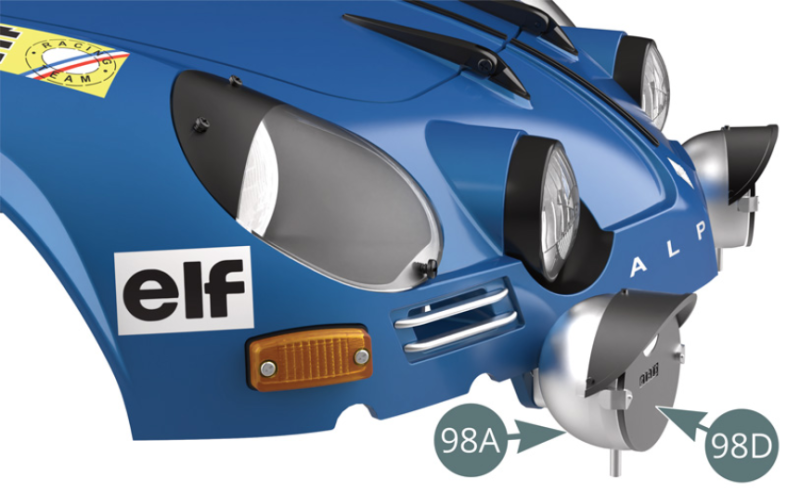
Etape 4
The cover with beam guide (98D) is attached to the right fog light housing (98A).

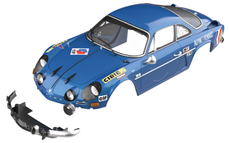
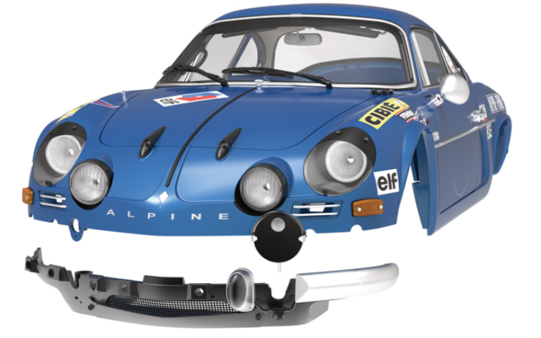
Positionner le support de phare antibrouillard droit 98E sur le côté gauche du bas de caisse avant 96A et le fixer avec une vis QM.
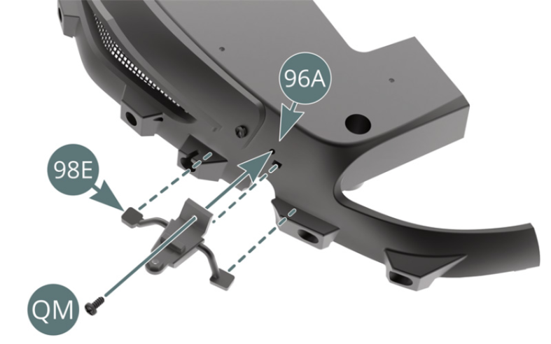
Etape 5
Position the right fog light bracket (98E) on the left side of the front rocker panel (96A) and secure it with a QM screw.

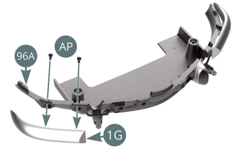
Positionner le pare-chocs avant droit 1G sur le bas de caisse avant 96A et le fixer avec deux vis AP.
Positionner le caoutchouc de butoir de pare-chocs droit 1J sur le bas de caisse avant 96A et le fixer avec une vis TP.

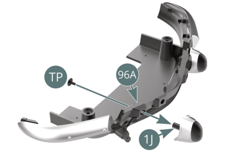
Schéma d’assemblage
Place the right front bumper (1G) on the front rocker panel (96A) and secure it with two AP screws. Position the right bumper rubber (1J) on the front rocker panel (96A) and secure it with a TP screw.
Vue générale


Kit 99 - Assemblage de la carrosserie, du châssis et des accessoires. Test de fonctionnement
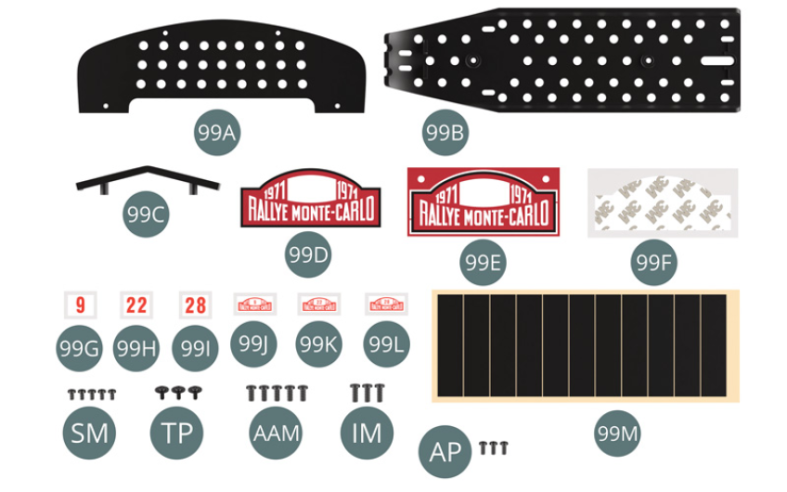
Parts of kit
Etape 1
- 99J Car roof sticker #9 (x 4)
- 99K Car roof sticker #22 (x 4)
- 99L Car roof sticker #28 (x 4)
- 99M Adhesive tape (x 11)
- Screw SM M 1.7 x 3 mm (x 5)
- Screw TP M 1.7 x 4 x 5.5 mm (x 3)
- Screw AAM M 2.3 x 5 mm (x 5)
- Screw IM M 2.3 x 6 mm (x 3)
- Screw AP M 1.7 x 4 mm (x 3)
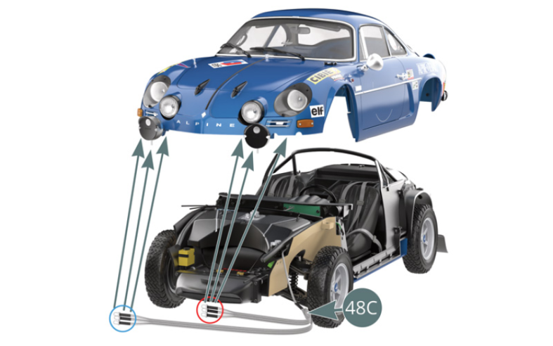
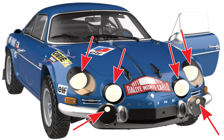
Avant de fixer la carrosserie sur le châssis, il est nécessaire d’installer les trois ampoules LED de la partie la plus courte du câble 48C (cercle rouge) dans les phares à l’avant gauche de la carrosserie, et les trois ampoules LED de la partie la plus longue du câble 48C (cercle bleu) dans les phares à l’avant droit de la carrosserie.
Commencer par rapprocher la carrosserie du châssis en veillant à laisser une distance suffisante pour pouvoir accéder aux câble et les connecter comme indiqué aux étapes suivantes.
Veiller à ne pas endommager le rétroviseur extérieur gauche et les poignées à l’intérieur des portières pendant l’assemblage.

Etape 2
Before attaching the body to the chassis, it is necessary to install the three LED lightbulbs of the shortest part of the cable (48C) (red circle) into the headlights at the left front of the body, and the three LED lightbulbs of the longest part of the cable (48C) (blue circle) into the headlights at the right front of the body. Start by bringing the body closer to the chassis, making sure to leave sufficient distance to access the cables and connect them as explained in the following steps. Be careful not to damage the left exterior mirror and the inner door handles during assembly.
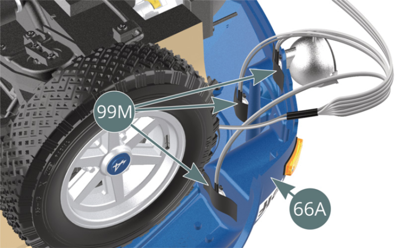
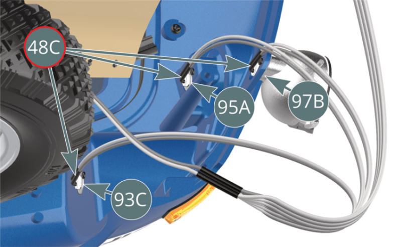
Connecter les trois ampoules LED du câble 48C le plus court dans les phares gauche 93C, 95A et 97B, puis fixer les câbles sur la carrosserie 66A avec du ruban adhésif 99M (illustrations ci-dessus).

Etape 3
Connect the three LED lightbulbs of the shortest cable (48C) into the left headlights (93C, 95A and 97B), then secure the cables to the body (66A) with adhesive tape (99M) (illustrations above).

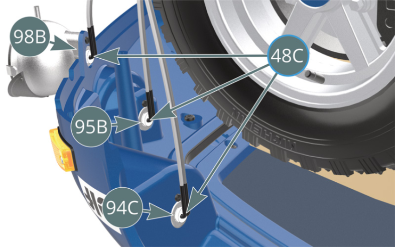
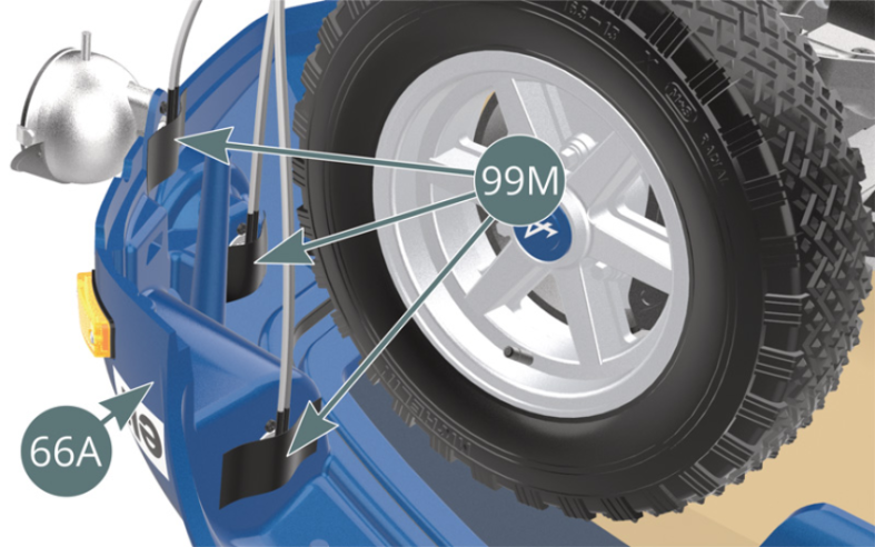
Connecter les trois ampoules LED du câble 48C le plus long dans les phares droits 98B, 95B et 94C, puis fixer les câbles sur la carrosserie 66A avec du ruban adhésif 99M (illustrations ci-dessus).


Etape 4
Connect the three LED lightbulbs of the longest cable (48C) into the right headlights (98B, 95B and 94C), then secure the cables to the body (66A) with adhesive tape (99M) (illustrations above).
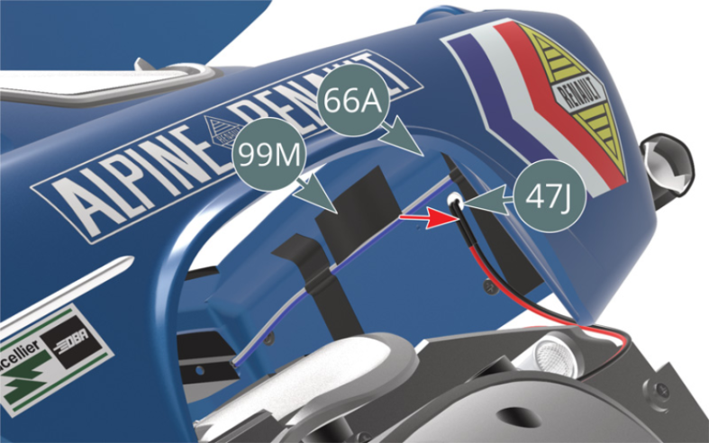
Fixer ensuite le câble 48C le plus long sur la face intérieure de l’avant de la carrosserie 66A avec du ruban adhésif 99M. À l’arrière de la voiture, connecter le câble H 47J (rouge-noir) dans le logement situé sur la face intérieure du panneau arrière de la carrosserie 66A, puis fixer le câble avec du ruban adhésif 99M.
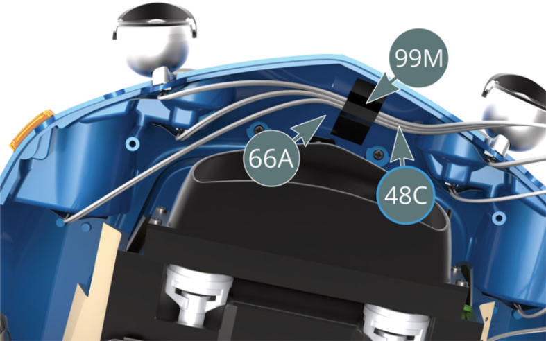

Etape 5
Then attach the longest cable (48C) to the inside of the front of the body (66A) with adhesive tape (99M). At the rear of the car, connect cable H (47J) (red-black) into the slot on the inside of the rear body panel (66A), then secure the cable with adhesive tape (99M).

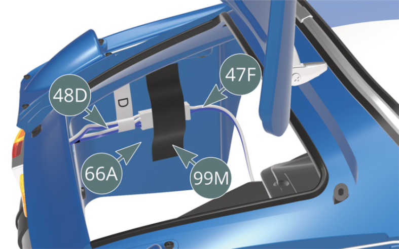
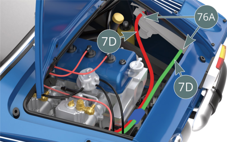
Connecter les câbles D 48D et D 47F (bleu-blanc) puis les fixer sur la paroi intérieure arrière gauche du compartiment moteur avec du ruban adhésif 99M. Rapprocher avec précaution la carrosserie et le châssis, puis ouvrir le capot moteur et fixer les deux conduites d’huile 7D (surlignés en rouge et en vert) sur le côté du boîtier de ventilateur de radiateur d’huile 76A.


Etape 6
Connect cables D (48D&47F) (blue-white) then secure them to the left rear inner wall of the engine compartment with adhesive tape (99M). Carefully bring the body and chassis together, then open the engine cover and attach the two oil lines (7D) (highlighted in red and green) to the side of the oil cooler fan housing (76A).
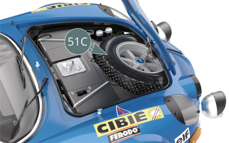
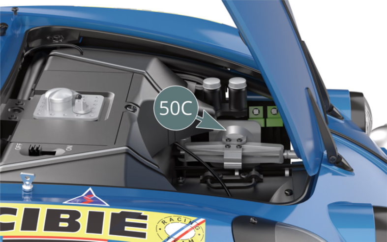
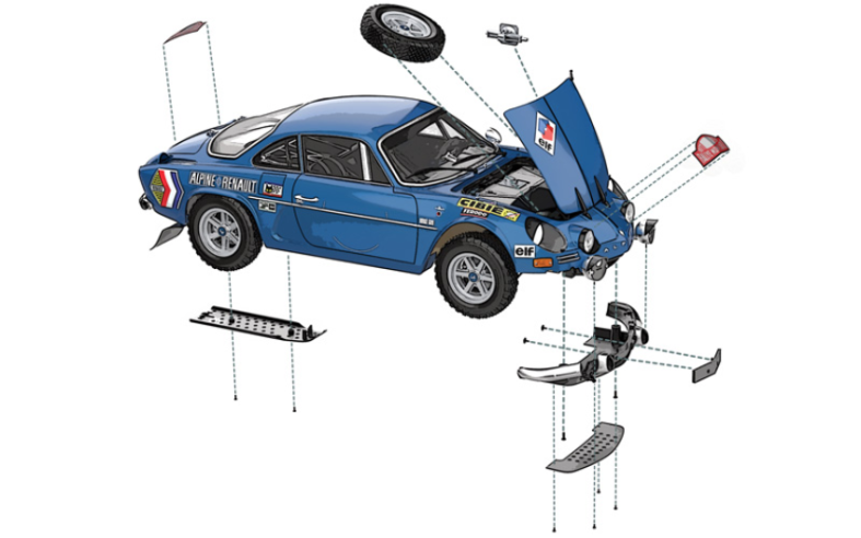
Ouvrir le capot avant et placer le cric 50C et la roue de secours 51C dans le compartiment avant (illustrations ci-dessus).

Etape 7
Open the front hood and place the jack (50C) and spare wheel (51C) in the front compartment (illustrations above).

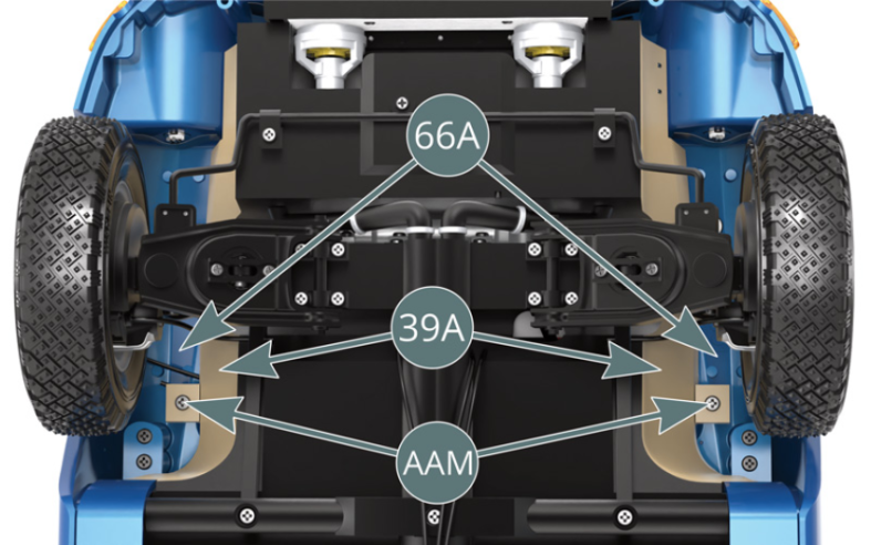
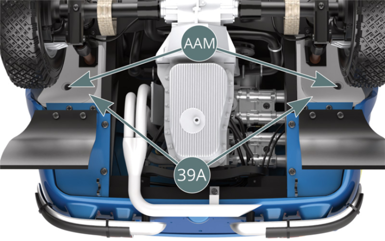
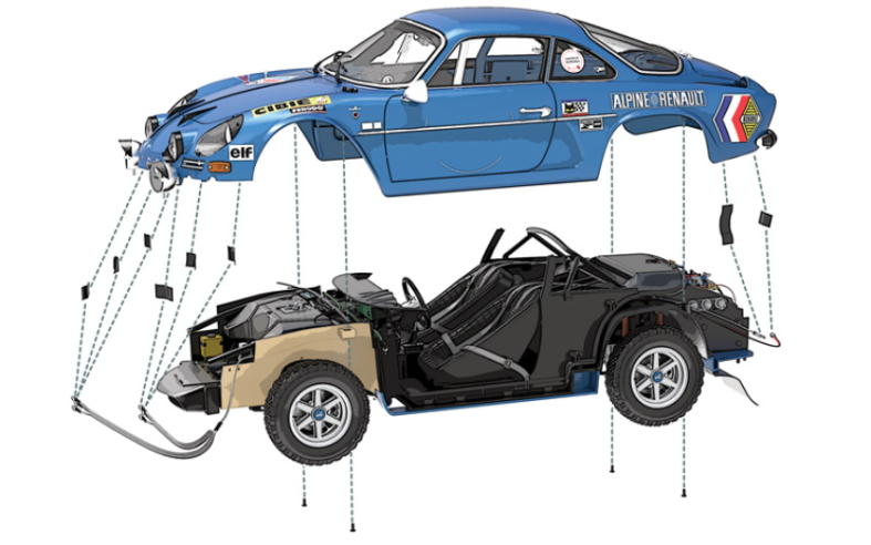
Assembler la carrosserie et le châssis, puis fixer le plancher du châssis 39A sur la carrosserie 66A avec deux vis AAM près des roues avant et deux vis AAM près des roues arrière (illustrations ci-dessus).


Etape 8
Assemble the body and chassis, then secure the chassis floor (39A) to the body (66A) with two AAM screws near the front wheels and two AAM screws near the rear wheels (illustrations above).
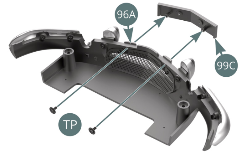
Positionner le support de plaque d’immatriculation 99C sur le bas de caisse avant 96A et le fixer avec deux vis TP.

Etape 9
Position the license plate holder (99C) on the front rocker panel (96A) and secure with two TP screws.
Positionner le bas de caisse avant 96A sur les montants de la carrosserie 66A, en plaçant les supports des phares antibrouillard droit 98E et gauche 97E sur les chevilles des boitiers de phares antibrouillard droit 98A et gauche 97A, puis le fixer avec deux vis IM.
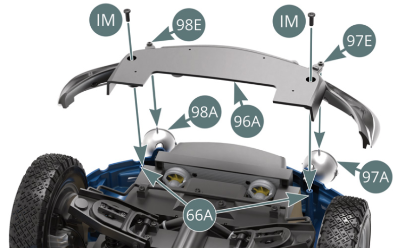
Etape 10
Position the front rocker panel (96A) on the bodywork pillars (66A), placing the right (98E) and left (97E) fog light supports on the pegs of the right (98A) and left fog light housings ( 97A), then secure with two IM screws.

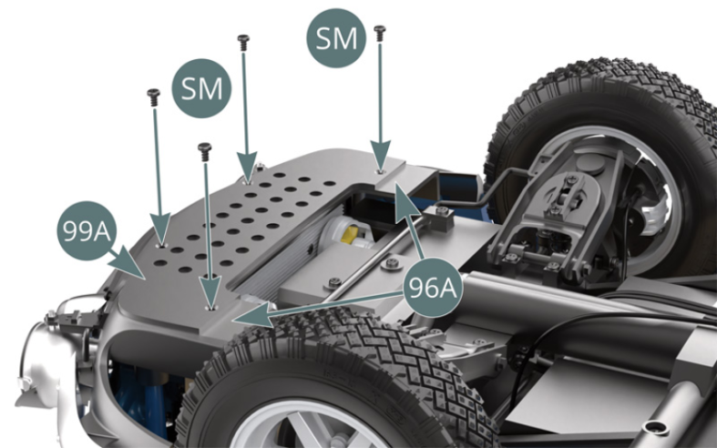
Positionner la plaque de protection du moteur 99A sur le bas de caisse avant 96A et la fixer avec quatre vis SM.
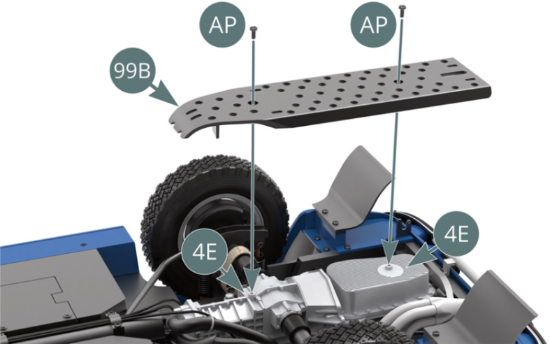
Positionner la plaque de protection de la transmission 99B sur le carter d’huile et de transmission 4E, puis la fixer avec deux vis AP.


Etape 11
Position the engine protection plate (99A) on the front rocker panel (96A) and secure with four SM screws. Position the transmission protection plate (99B) on the oil pan and transmission (4E), then secure it with two AP screws.
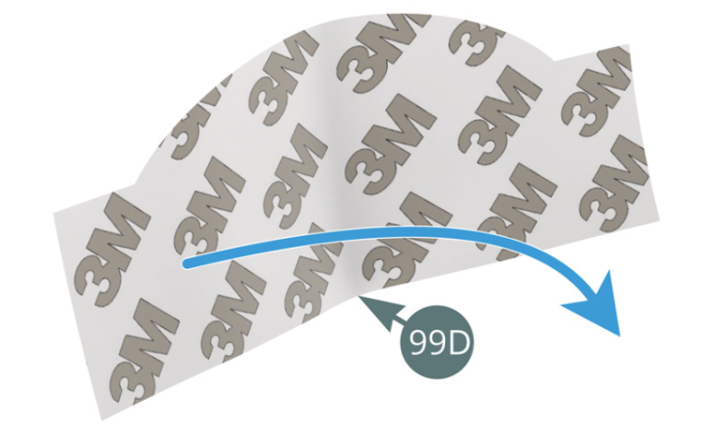
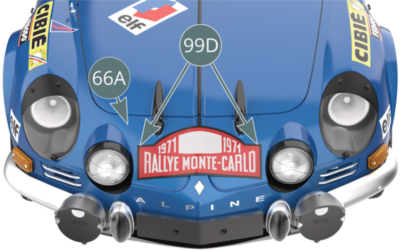
Détacher l’un des supports papier de l’adhésif double-face 99F et fixer celui-ci à l’arrière de la plaque de rallye avant 99D.
Plier légèrement la plaque de rallye avant 99D pour l’adapter à la courbure de l’avant de la carrosserie 66A. Détacher l’autre papier support de l’adhésif double-face et fixer la plaque de rallye avant sur la carrosserie 66A.
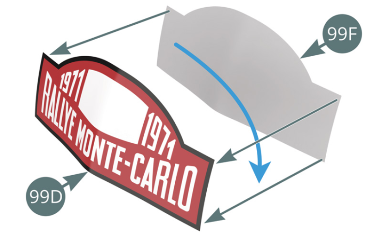

Remove the paper backing (one side only) from the double-sided adhesive (99F) and attach it to the back of the front rally plate (99D). Slightly bend the front rally plate (99D) to fit the curve of the front of the body (66A). Then remove the paper backing of the other side of the double-sided adhesive and attach the front rally plate onto the body (66A).

Etape 12
Détacher l’un des supports papier de l’adhésif double-face 99F et fixer celui-ci à l’arrière de la plaque de rallye arrière 99E (après l’avoir détachée de son support rectangulaire).
Plier légèrement la plaque de rallye arrière 99E pour l’adapter à la courbure du capot moteur 89A. Détacher l’autre papier support de l’adhésif double-face et fixer la plaque de rallye arrière sur le capot moteur 89A.
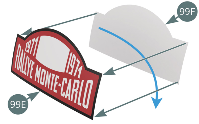
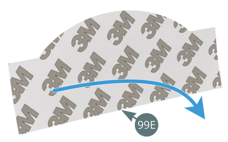
Remove the paper backing (one side only) from the double-sided adhesive (99F) and attach it to the back of the rear rally plate (99E) (first detach the rally plate of its rectangular support). Slightly bend the rear rally plate (99E) to fit the curve of the engine cover (89A). Then remove the paper backing of the other side from the double-sided adhesive and attach the rear rally plate to the engine cover (89A).
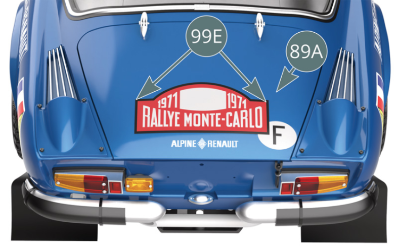
Schéma d’assemblage


Vue générale

Test de fonctionnement

Etape 1

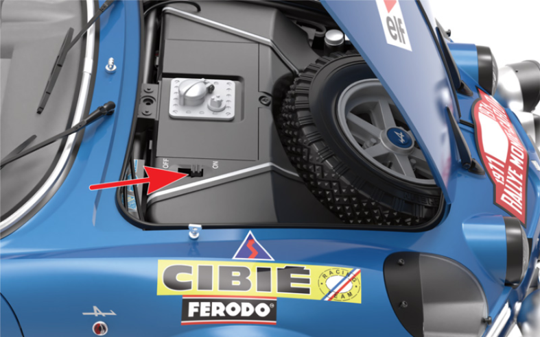
S’assurer que les piles sont placées dans le compartiment à piles. Mettre l’interrupteur de batterie en position «ON» (flèche rouge).
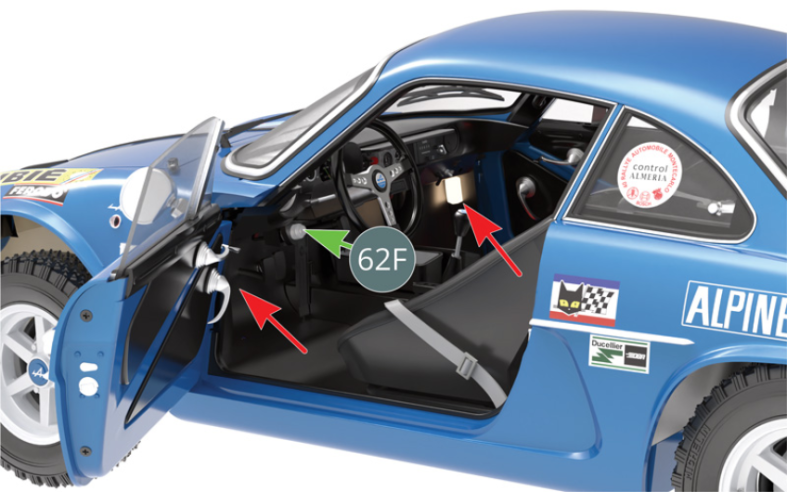
Ouvrir la portière gauche et vérifier que l’éclairage de l’habitacle s’allume (flèches rouges). Appuyer sur le contacteur de démarrage 62F pour allumer les autres éclairages.

Etape 2
Make sure the batteries are placed in the battery compartment. Place the battery switch in the “ON” position (red arrow). Open the left door and check that the cabin lighting turns on (red arrows). Press the start switch (62F) to turn on the other lights.

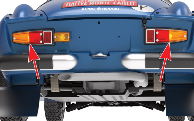
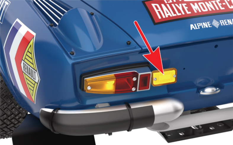
Vérifier que les feux arrière et les phares s’allument (flèches rouges).
Etape 3
Check that the taillights and headlights light up (red arrows).


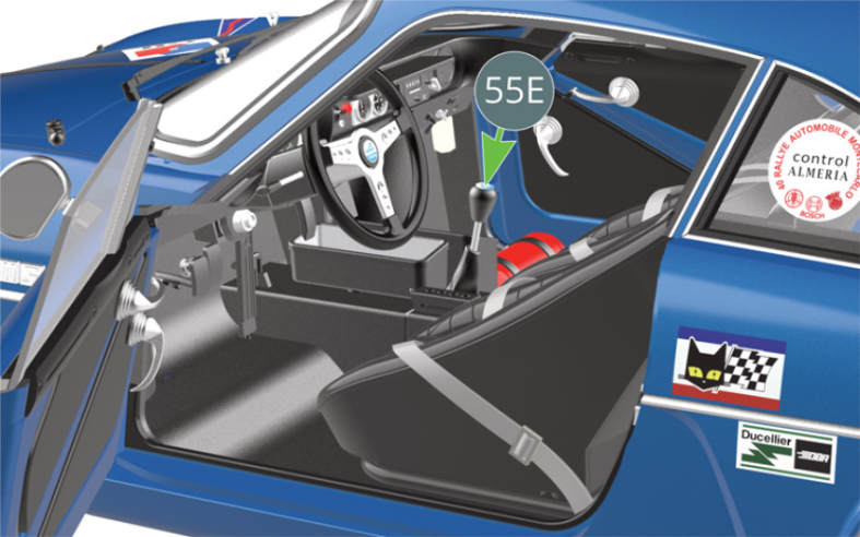
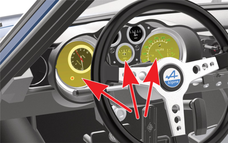
Vérifier que le rétro éclairage des instruments du tableau de bord s’allume (flèches rouges).
Pousser le levier de vitesses 55E vers le bas pour vérifier que le feu de recul s’allume.

Etape 4
Check that the dashboard instrument backlight functions (red arrows). Push the gear lever (55E) down to verify that the reverse light switches on.

Le feu de recul est allumé.
Après avoir testé le fonctionnement des commandes électriques, mettre l’interrupteur de batterie en position «OFF». Prendre soin de retirer les piles de leur compartiment en cas de non utilisation prolongée afin qu’elles ne coulent pas.
Kit 100 - Montage de la serrure de coffre et application de la dernière série d’autocollants
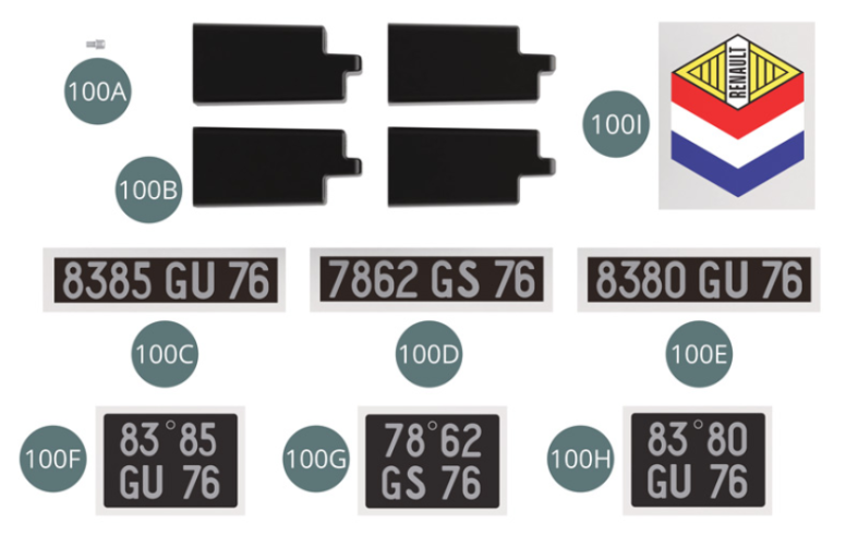
Parts of kit
The reversing light is on. After having tested the working of the electrical controls, turn the battery switch to the “OFF” position. Make sure to remove the batteries from their compartment in case of prolonged non-use so that they do not leak.

Etape 1
- 100F Sticker rear registration plate car #9 (x 2)
- 100G Sticker rear registration plate car #22 (x 2)
- 100H Sticker rear car registration plate car #28 (x 2)
- 100I Sticker roof car #28 (x 2)
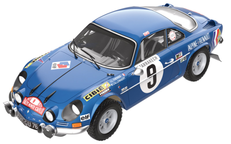
L’application du jeu d’autocollants de la voiture n° 9 est donnée à titre d’exemple.
Appliquer l’autocollant de plaque immatriculation avant 100C de la voiture n° 9 sur le support de plaque d’immatriculation 99C.
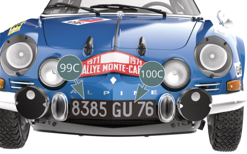
Etape 2
The application of car sticker set #9 is given as an example. Apply the front license plate sticker (100C) of car #9 to the license plate holder (99C).

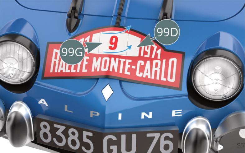
Détacher l’autocollant 99G (voiture n° 9) avec son film supérieur du support papier. L’appliquer sur la plaque de rallye avant 99D, puis retirer le film supérieur.
Etape 3
Detach the sticker (99G) (car #9) including its top film from the paper support. Apply it to the front rally plate (99D), then remove the top film.

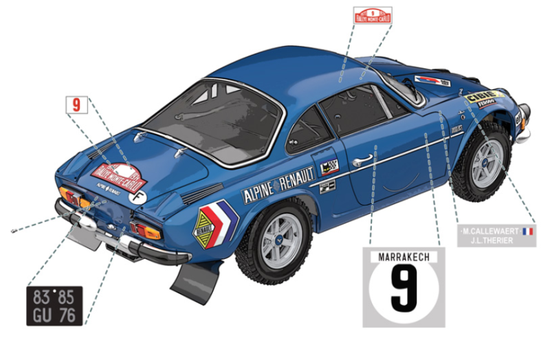
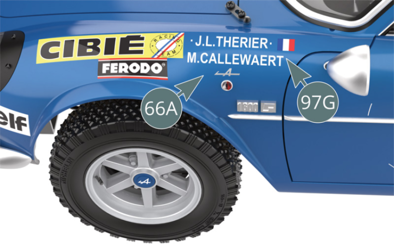
Appliquer l’autocollant gauche 97G «noms des pilotes» de la voiture n° 9 en haut de l’aile gauche de la carrosserie 66A.

Etape 4
Apply the left sticker (97G) “driver names” of car #9 to the top of the left wing of the body (66A).
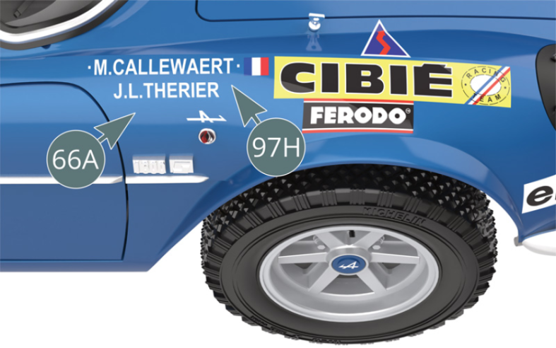
Appliquer l’autocollant droit 97H «noms des pilotes» de la voiture n° 9 en haut de l’aile droite de la carrosserie 66A.

Etape 5
Apply the right sticker (97H) “driver names” of car #9 to the top of the right wing of the bodywork (66A).
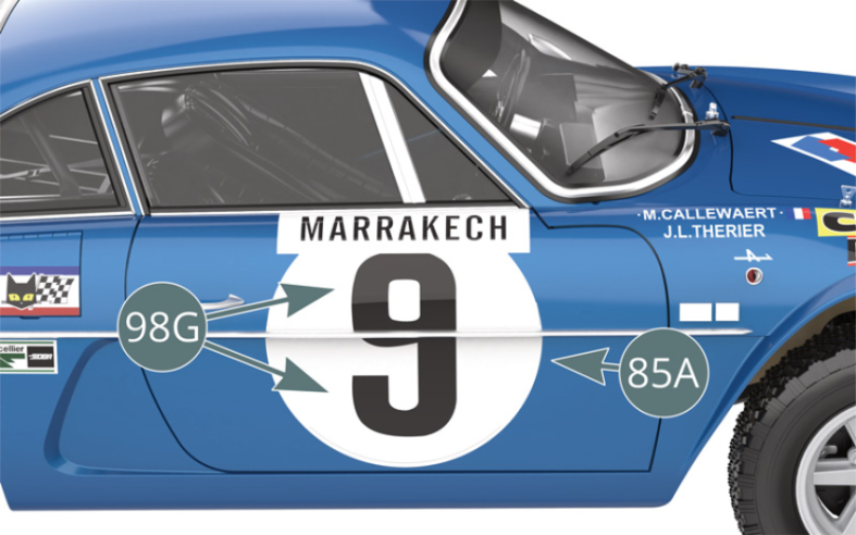
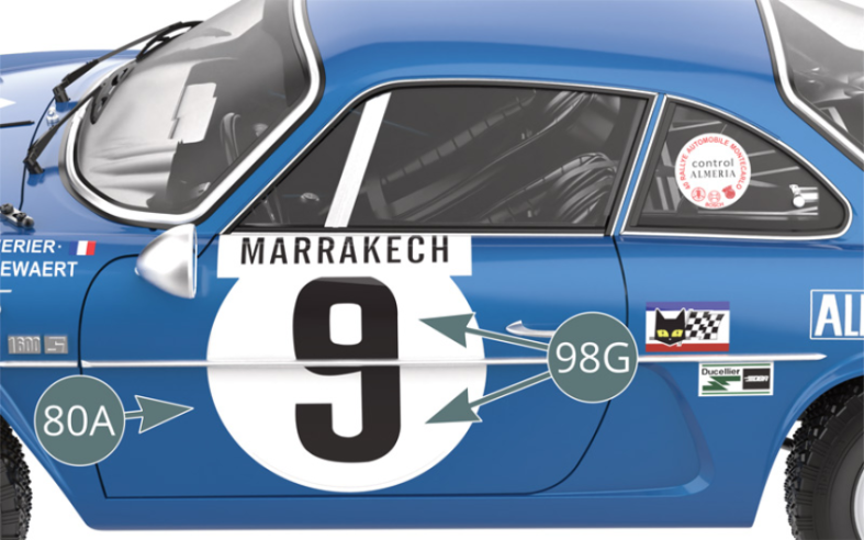
Appliquer l’autocollant de portière 98G de la voiture n° 9 (en deux parties) sur la portière droite 85A en se servant des repères de positionnement qui s’y trouvent.
Etape 6
Apply the door sticker (98G) (which is in two parts) from car #9 to the right door (85A) using the positioning marks.

Appliquer l’autocollant de toit 99J de la voiture n° 9 au coin droit du toit de la carrosserie 66A en se servant des repères de positionnement qui s’y trouvent.
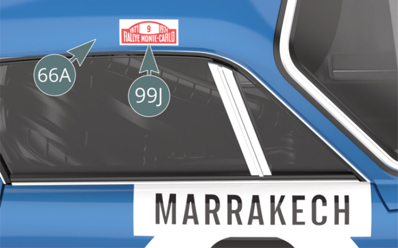
Etape 7
Apply the roof sticker (99J) of car # 9 to the right corner of the roof of the body (66A) using the positioning marks.

Appliquer l’autocollant de portière 98G de la voiture n° 9 (en deux parties) sur la portière gauche 80A en se servant des repères de positionnement qui s’y trouvent.

Etape 8
Apply the door sticker (98G) (which is in two parts) of car #9 to the left door (80A) using the positioning marks.
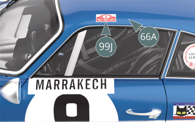
Appliquer l’autocollant de toit 99J de la voiture n° 9 au coin gauche du toit de la carrosserie 66A en se servant des repères de positionnement qui s’y trouvent.

Etape 9
Apply the roof sticker (99J) of car #9 to the left corner of the roof of the body (66A) using the positioning marks.
Pour la voiture n° 28 uniquement, appliquer l’autocollant de toit 100I sur le toit de la carrosserie 66A.
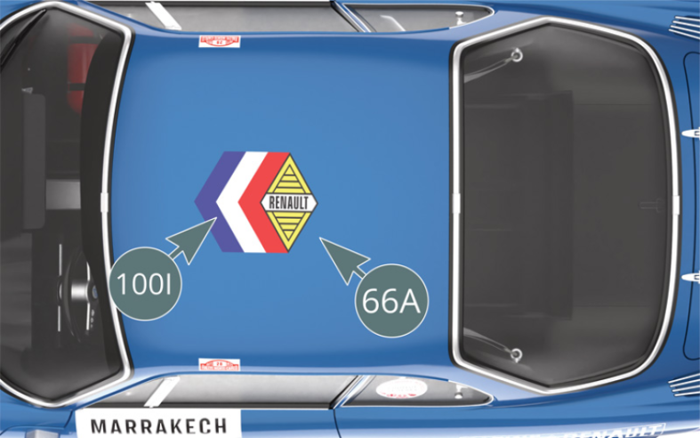
Etape 10
For car #28 only, apply the roof sticker (100I) to the roof of the body (66A).

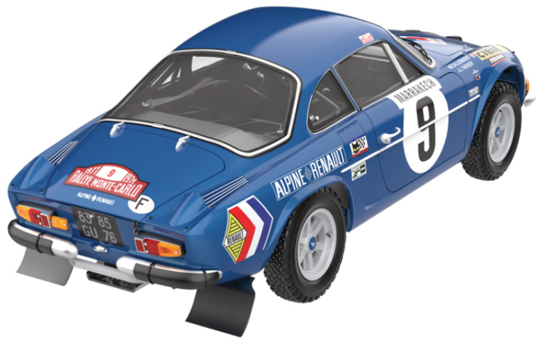
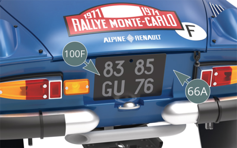
Appliquer l’autocollant de plaque immatriculation arrière 100F de la voiture n° 9 sur le panneau arrière de la carrosserie 66A, en veillant à aligner correctement les trous de la plaque et du panneau arrière.

Etape 11
Apply the rear license plate sticker (100F) from car #9 to the rear panel of the body (66A), making sure to correctly align the openings in the plate and rear panel.
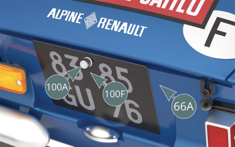
Positionner la serrure de coffre 100A sur l’autocollant de plaque immatriculation arrière 100F de la voiture n° 9 et sur le panneau arrière de la carrosserie 66A.

Etape 12
Place the trunk lock (100A) over the rear registration plate sticker (100F) of car # 9 and on the rear panel of the body (66A).
Détacher l’autocollant 99G (voiture n° 9) avec son film supérieur du support papier. L’appliquer sur la plaque de rallye arrière 99E, puis retirer le film supérieur.
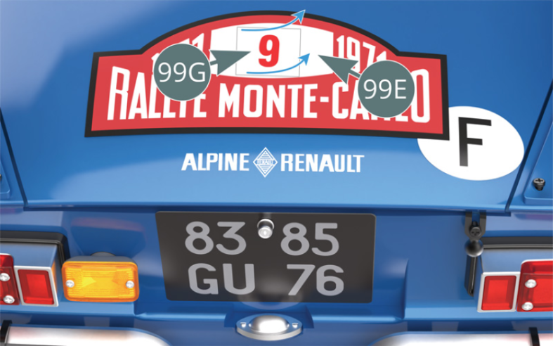
Etape 13
Detach the sticker (99G) (car #9) including its top film from the paper support. Apply it to the rear rally plate (99E), then remove the top film.

Utiliser les quatre chandelles de soutien 100B pour surélever la voiture.
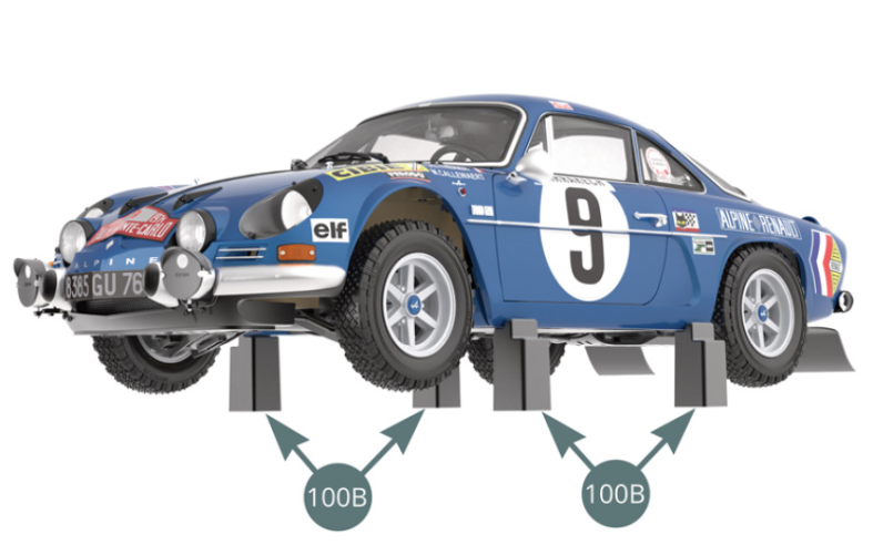
Schéma d’assemblage
Use the four support stands (100B) to raise the car.

Vue générale