English
 français
 Deutsch
 español
 italiano
 português


Box 13
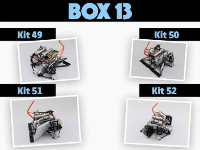
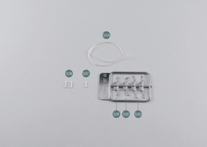
Kit 49 - Fils de bougies d’allumage
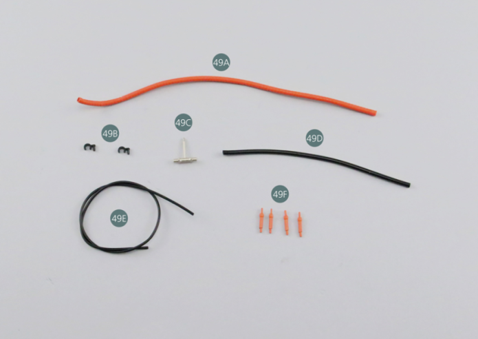
Parts of kit
- 49A Tuyau annelé
- 49B Support de tuyau (x 2)
- 49C Raccord de tuyau d’huile
- 49D Tuyau d’huile
- 49E Fil de bougie
- 49F Capuchon de bougie d’allumage (x 4)
Etape 1
- 49D Oil hose
- 49E Spark plug wire
- 49F Spark plug cap (x 4)

Positionner les deux supports de tuyau 49B sur le couvre-culasse gauche 30B.

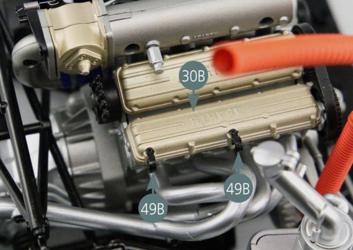
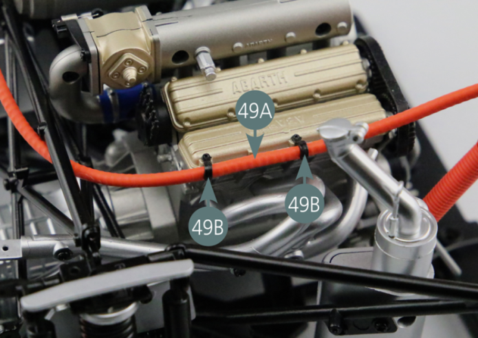
Etape 2
Position the two hose supports (49B) on the right cylinder head cover (30B).
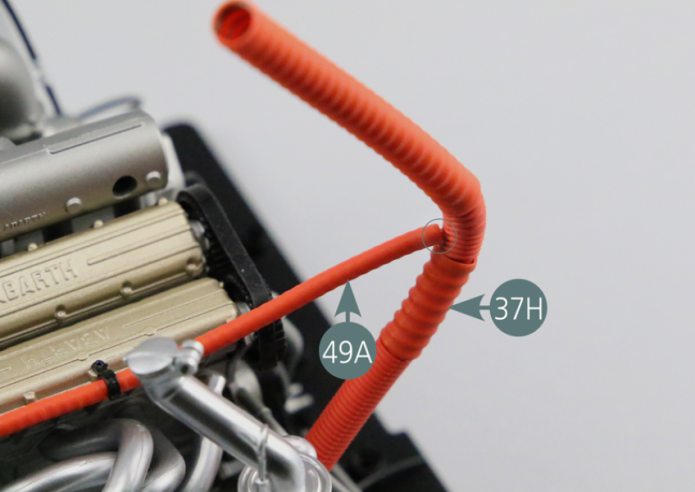
Positionner l’une des extrémités du tuyau annelé 49A sur le réservoir d’huile #6 28F.
Passer le tuyau 49A à travers les deux supports 49B, puis le raccorder à la conduite d’air #2 37H.
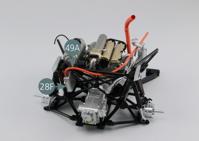

Place one end of the corrugated hose (49A) on the oil tank #6 (28F). Pass the hose (49A) through the two support brackets (49B), then connect it to air duct #2 (37H).

Etape 3
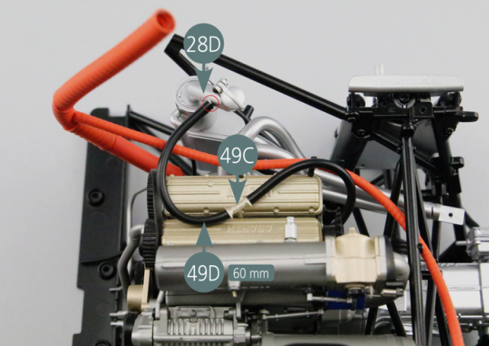
Placer le raccord de tuyau d’huile 49C sur la culasse moteur 30A. Couper deux sections de 60 mm de long dans le tuyau d’huile 49D. Raccorder la première section au bloc moteur droit 29A et au raccord 49C, puis raccorder la seconde section à la goulotte de remplissage d’huile #4 28D et au raccord 49C.
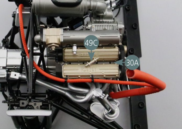
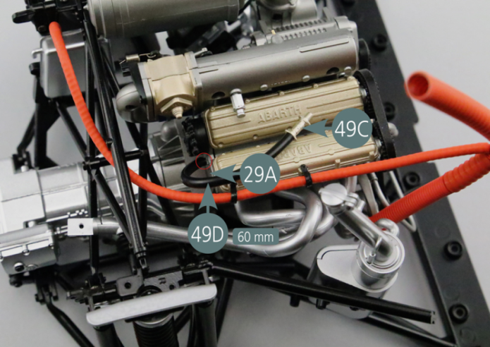
Place the oil hose fitting (49C) onto the engine cylinder head (30A). Cut two 60mm long sections from the oil hose (49D). Connect the first section to the right engine block (29A) and fitting (49C), then connect the second section to oil filler neck #4 (28D) and fitting (49C).

Etape 4

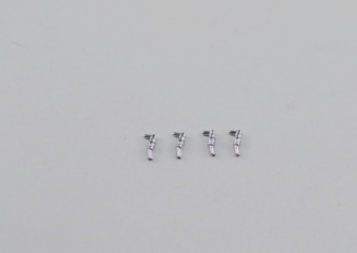
Couper quatre sections de 30 mm, 40 mm, 55 mm et 65 mm de long dans le fil de bougie 49E. Insérer un capuchon de bougie d’allumage 49F dans l’une des extrémités de chaque section. Connectez ensuite les quatre capuchons 49F sur la culasse moteur 30A.
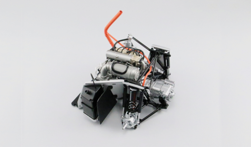
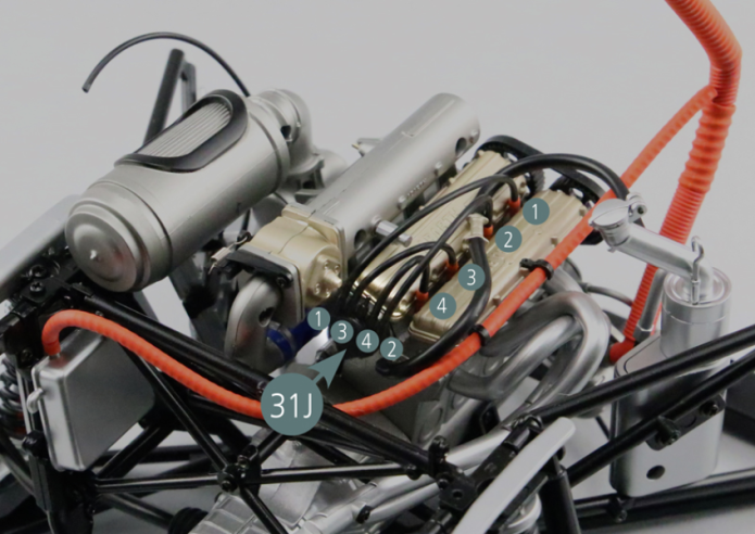
Connecter les extrémités restées libres de chaque fil de bougie au distributeur d’allumage 31J en suivant bien l’ordre indiqué sur la photo.
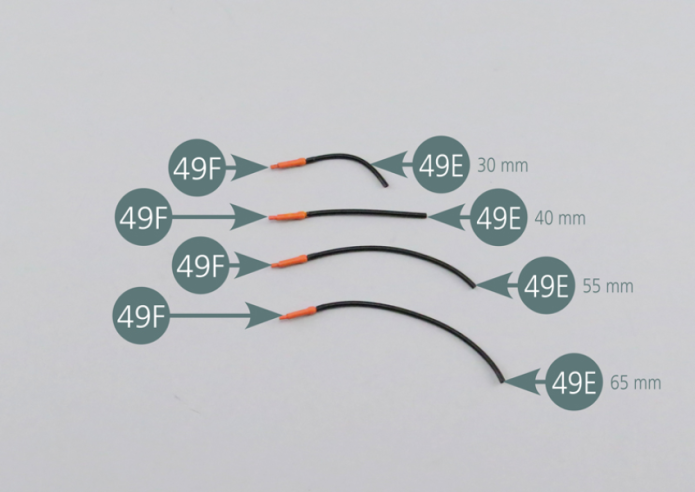
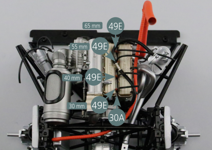
Cut four sections of 30mm, 40mm, 55mm and 65mm long from the spark plug wire (49E). Insert a spark plug cap (49F) into one end of each section. Then connect the four caps (49F) to the engine cylinder head (30A). Connect the remaining free ends of each spark plug wire to the ignition distributor (31J) following the order shown in the photo.
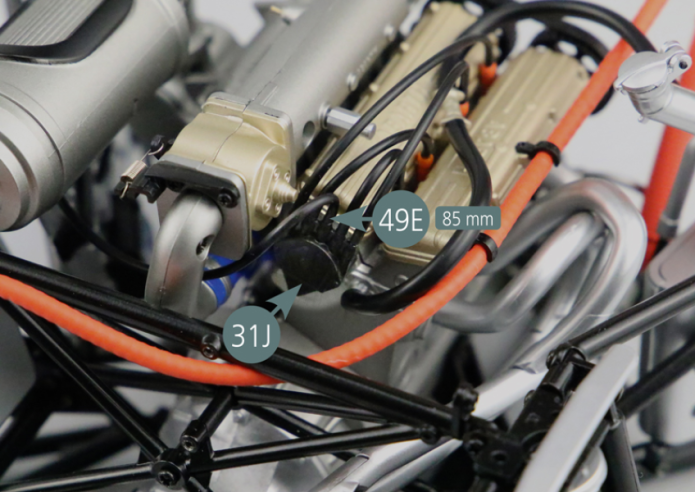
Etape 5


Couper une section de 85 mm de long dans le fil de bougie 49E et connecter une extrémité à la bobine d’allumage 28I.
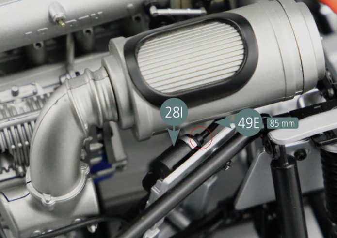
Etape 6
Cut a section of 85mm long from the spark plug wire (49E) and connect one end to the ignition coil (28I).

Connecter l’autre extrémité du fil de 85 mm au distributeur d’allumage 31J comme indiqué sur la photo.
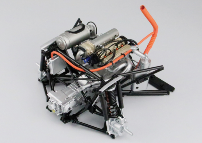
Vue générale
Connect the other end of the 85mm long wire to the ignition distributor (31J) as shown in the photo.
Kit 50 - Tuyaux d’alimentation en carburant
Parts of kit

Etape 1
- 50D Injectors (x 4)
- 50E Elbow fitting (x 2)
- 50F Fitting (x 2)
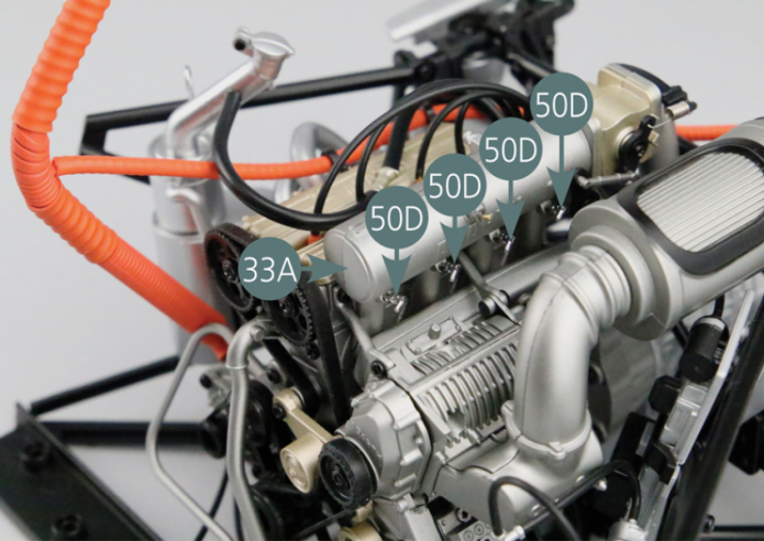
Détacher les quatre injecteurs 50D de la grappe de moulage et les positionner sur le collecteur d’admission #1 33A.
Etape 2
Detach the four injectors (50D) from the sprue and place them on intake manifold #1 (33A).


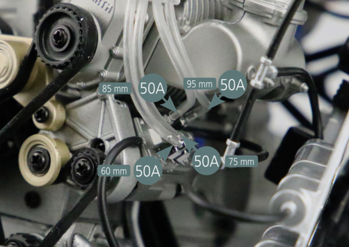
Couper quatre sections de 60 mm, 75 mm, 85 mm et 95 mm de long dans le tuyau de carburant 50A. Raccorder une extrémité de chaque section à un injecteur 50 D comme indiqué sur la photo. Positionner les attaches 50B et 50C comme indiqué.
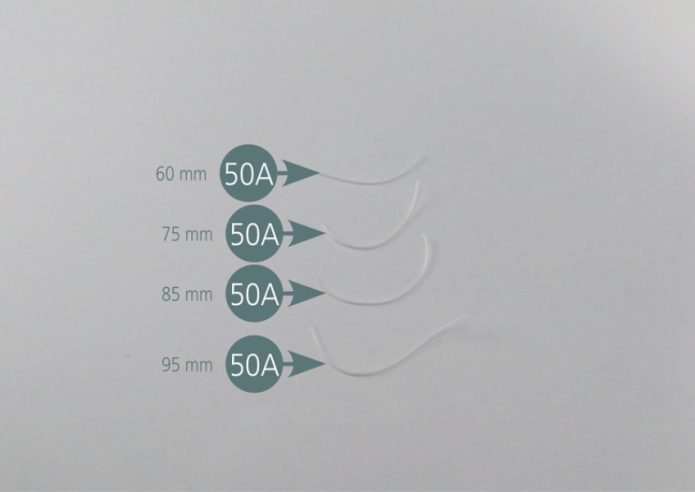
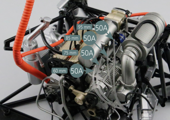
Cut four sections of 60mm, 75mm, 85mm and 95mm long from the fuel hose (50A). Connect one end of each section to an injector (50D) as shown in the photo. Position the attachments (50B&50C) as indicated.
Etape 3


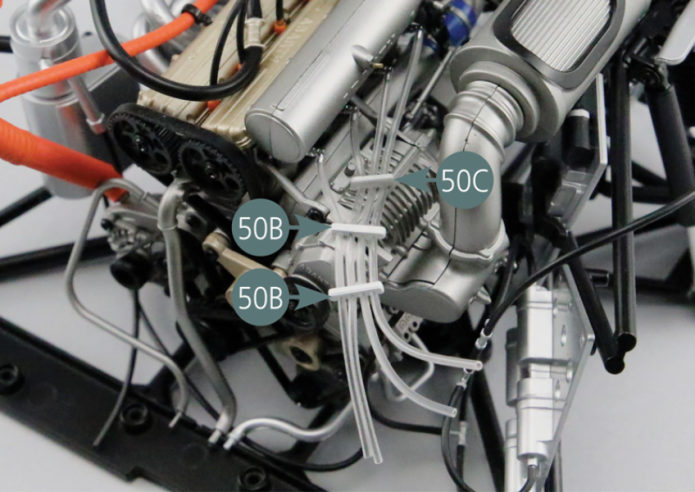
Détacher les raccords 50E et 50F de la grappe de moulage, puis les positionner comme indiqué sur la photo. Raccorder ensuite les quatre tuyaux de carburant, selon leur longueur, comme indiqué.
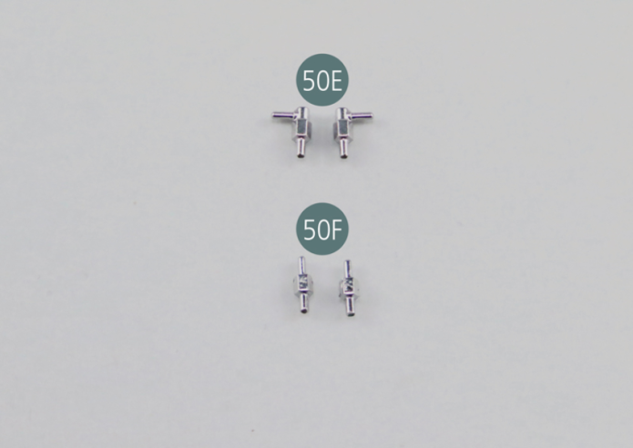
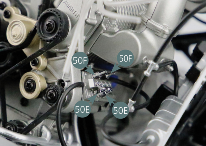
Detach the fittings (50E&50F) from the sprue, and position them as shown in the photo. Then connect the four fuel hoses, according to their length, as shown.
Vue générale

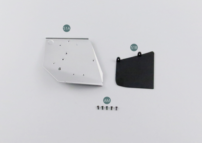
Kit 51 - Cloison de protection et garde-pierre gauche
Parts of kit

Etape 1
- Screw AM M 1.7 x 4 mm (x 5)
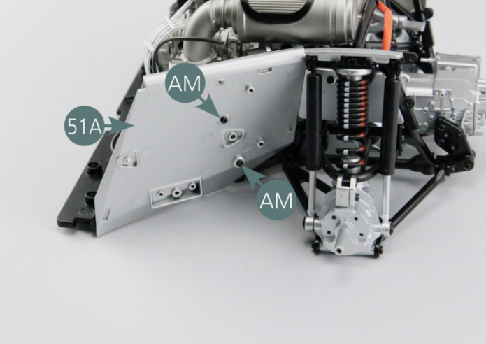
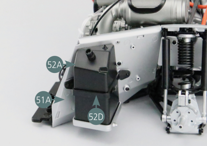
Positionner la cloison de protection 51A sur le côté gauche du berceau moteur et la fixer avec deux vis AM.

Etape 2
Position the bulkhead (51A) on the left side of the engine cradle and secure with two AM screws.
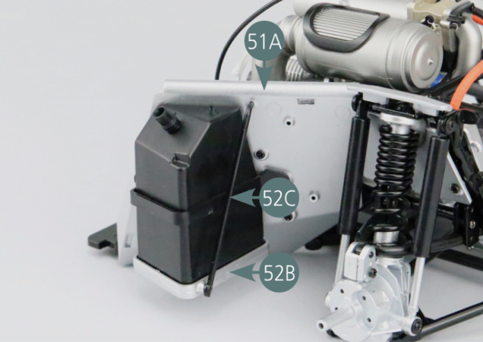
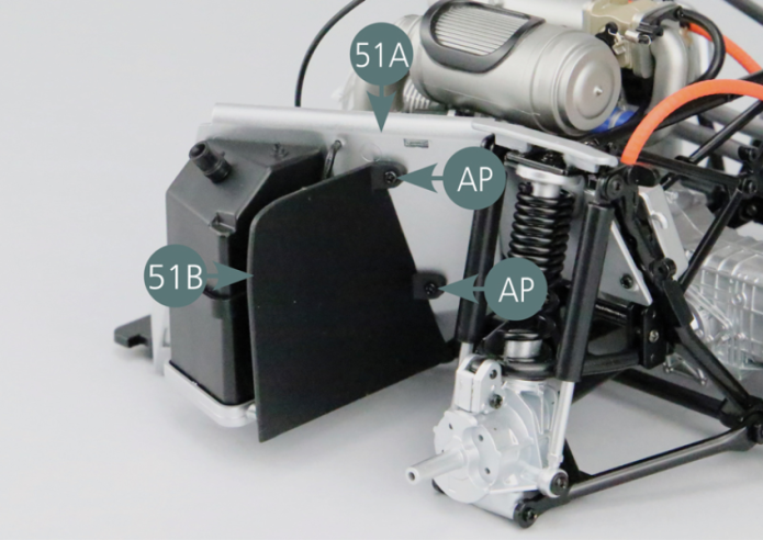
Insérer deux vis AM dans la cloison 51A comme indiqué sur la photo.
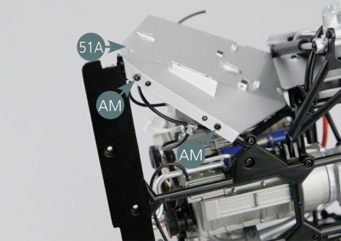
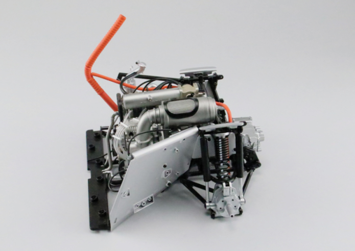
Vue générale
Insert two AM screws into the bulkhead (51A) as shown in the photo.

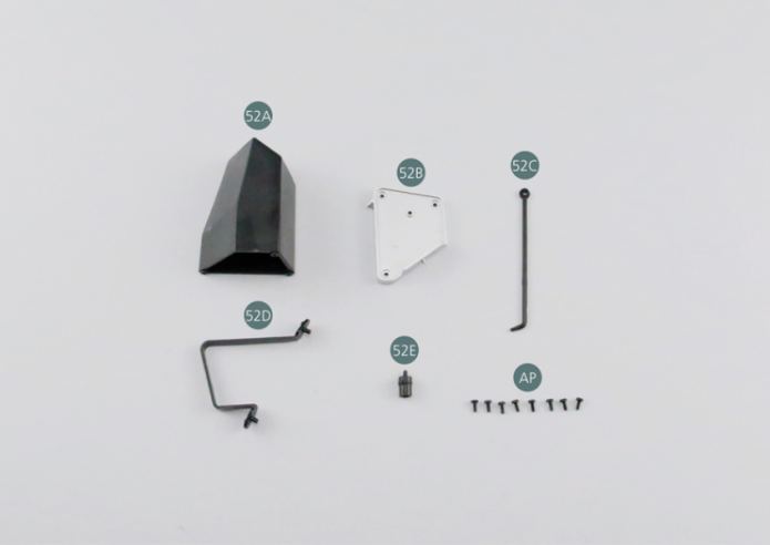
Kit 52 - Réservoir de carburant gauche
Parts of kit
Etape 1
- 52D Support leg
- 52E filler neck
- Screw AP P 1.7 x 4 mm (x 8)
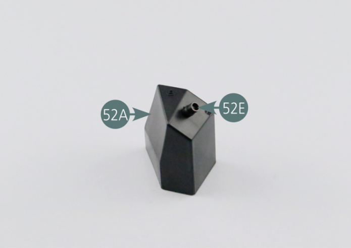
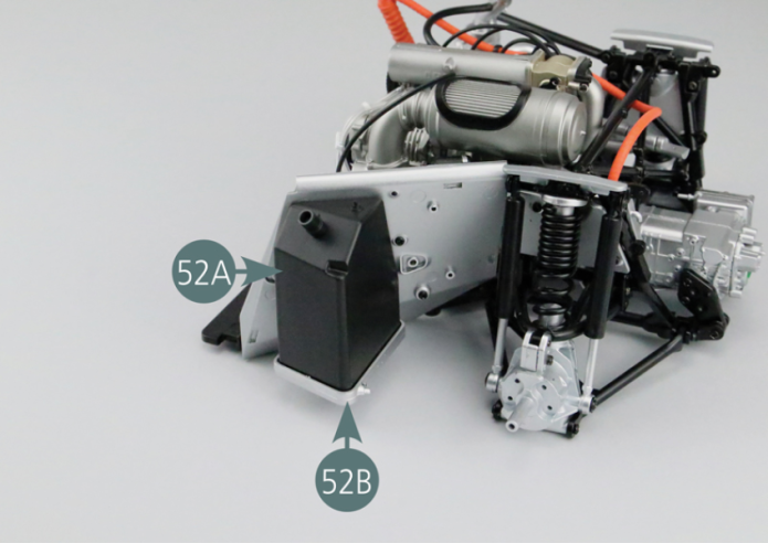
Positionner le goulot de remplissage 52E sur le réservoir de carburant gauche 52A.

Etape 2
Place the filler neck (52E) onto the left fuel tank (52A).
Positionner le support de réservoir 52B sur la cloison de protection gauche 51A et le fixer avec deux vis AP.
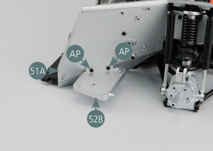
Etape 3
Position the tank support (52B) on the left bulkhead (51A) and secure it with two AP screws.

Positionner le réservoir de carburant gauche 52A sur le support 52B et le fixer par en dessous avec trois vis AP.

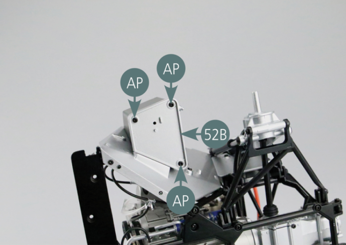
Etape 4
Place the left fuel tank (52A) on the support (52B) and secure from below with three AP screws.

Positionner la patte de soutien 52D sur la cloison de protection gauche 51A pour maintenir en place le réservoir de carburant gauche 52A.

Etape 5
Position the support leg (52D) on the left bulkhead (51A) to keep the left fuel tank (52A) in position.
Positionner la barre de renfort gauche 52C comme indiqué, puis fixer ses extrémités sur la cloison de protection gauche 51A et sur le support 52B.

Etape 6
Position the left reinforcement bar (52C) as shown, then attach its ends to the left bulkhead (51A) and to the tank support (52B).
Positionner le garde-pierre gauche 51B sur la cloison de protection gauche 51A et le fixer avec deux vis AP.

Etape 7
Position the left mudguard (51B) on the left bulkhead (51A) and secure with two AP screws.
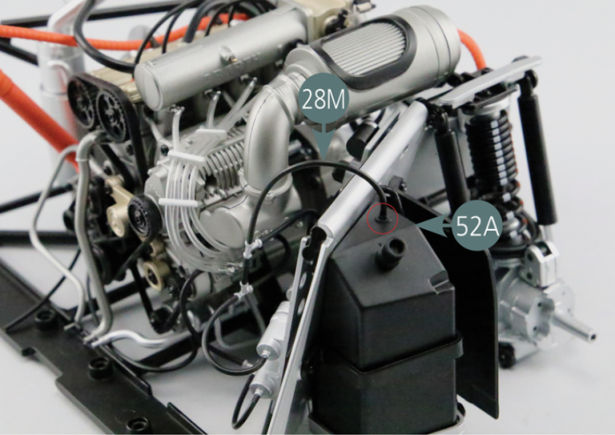
Raccorder la durite de carburant 28M au réservoir de carburant gauche 52A.
Vue générale
Connect the fuel hose (28M) to the left fuel tank (52A).