English
 français
 Deutsch
 español
 italiano
 português


Box 17
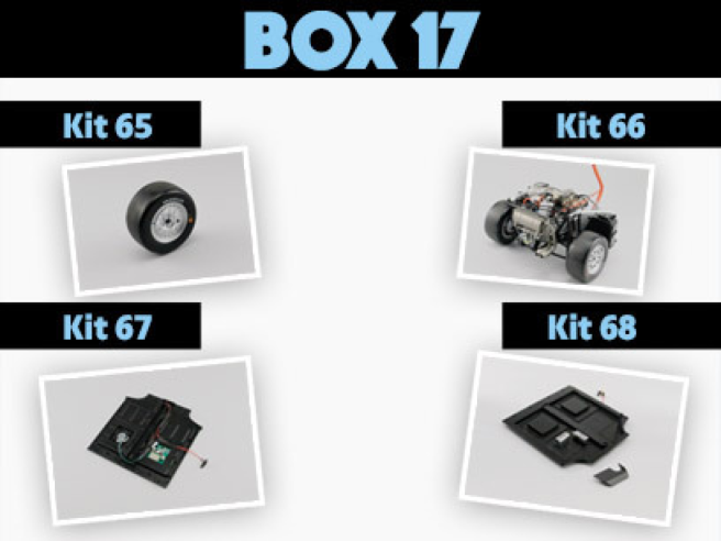
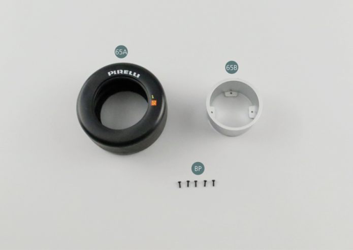
Kit 65 - Pneumatique de la seconde roue arrière
Parts of kit
- 65A Pneumatique
- 65B Jante de roue intérieure
- BP Vis P 1,7 x 5 mm (x 5)
Etape 1
- Screw BP M 1.7 x 5 mm (x 5)

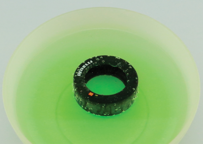
Plonger le pneumatique 65A dans de l’eau chaude pendant 30 secondes pour le ramollir.
Une fois sorti de l’eau, le sécher soigneusement, particulièrement la partie intérieure.
Etape 2
Immerse the tire (65A) in luke warm water for 30 seconds to soften it. Once out of the water, dry it carefully, especially the interior part.

Positionner la jante de roue intérieure 65B dans le pneumatique 65A. Vérifier que le pneumatique est positionné du bon côté (sans marquages).
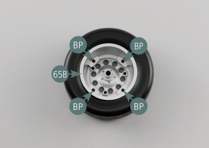
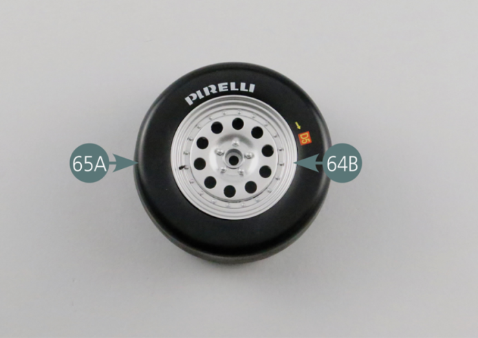
Retourner le pneumatique 65A et positionner la jante de roue extérieure 64B. Vérifier que le pneumatique est positionné du bon côté (avec marquages). Retourner à nouveau le pneumatique et fixer ensemble les jantes intérieure et extérieure avec quatre vis BP.
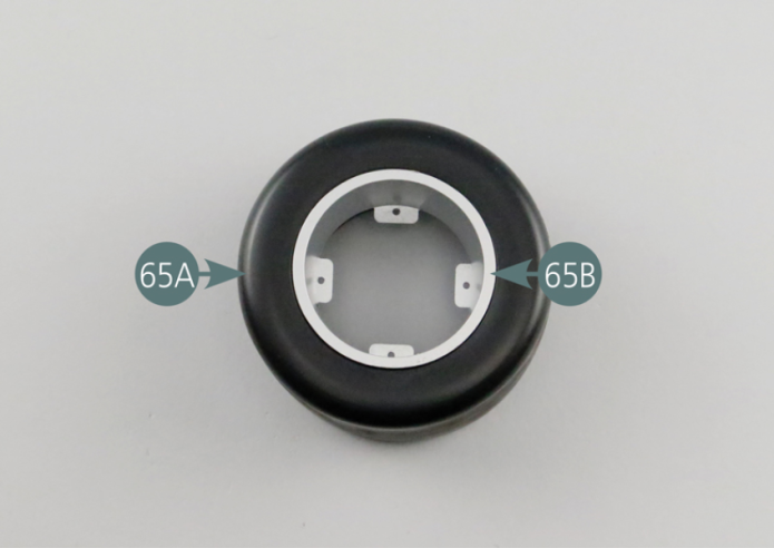

Place the inner wheel rim (65B) in the tyre (65A). Check that the tyre is correctly positioned (without markings).
Turn the tire (65A) over and position the outer wheel rim (64B). Check that the tire is placed on the correct side (with markings). Turn the tire over again and secure the inner and outer rims together with four BP screws.
Vue générale

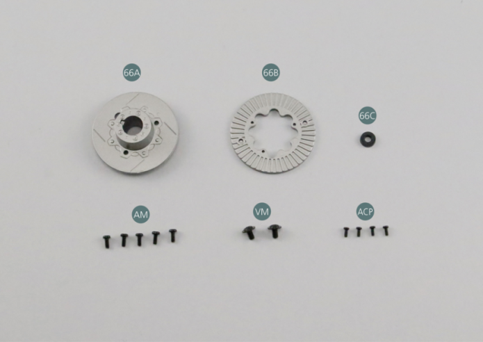
Kit 66 - Second frein à disque arrière
Parts of kit
Etape 1
- Screw AM M 1.7 x 4 mm (x 5)
- Screw VM M 3.0 x 4 mm (x 2)
- Screw ACP P 1.4 x 3 mm (x 4)
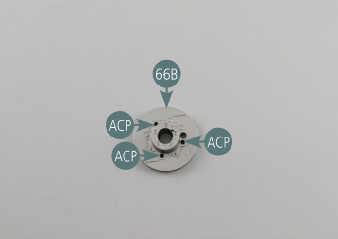
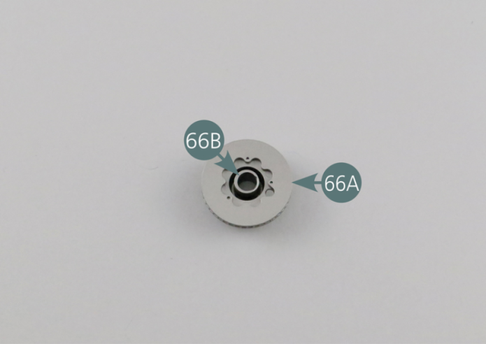
Positionner le disque de frein extérieur 66A sur le disque de frein intérieur 66B et le fixer avec trois vis ACP.
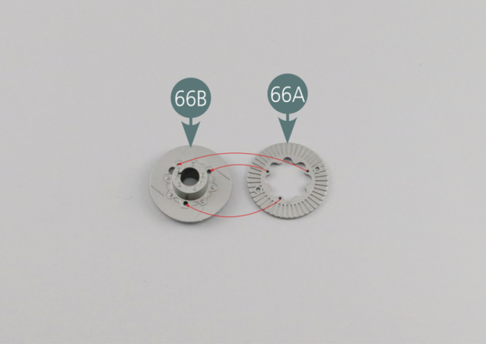

Place the outer brake disc (66A) on the inner brake disc (66B) and secure with three ACP screws.
Etape 2

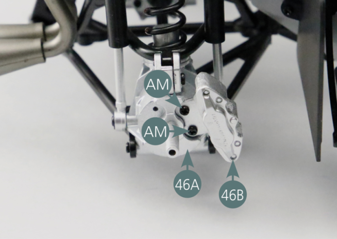
Positionner l’étrier de frein 46B sur le moyeu arrière droit 46A et le fixer avec deux vis AM.
Positionner le disque de frein sur le moyeu arrière droit 46A.


Etape 3
Position the brake caliper (46B) on the right rear hub (46A) and secure it with two AM screws. Position the brake disc on the right rear hub (46A).
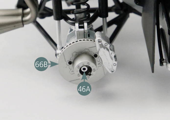
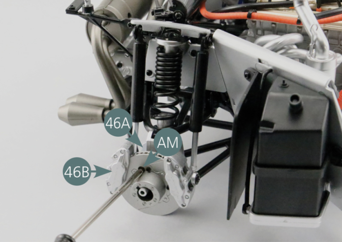
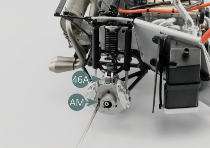
Positionner le second étrier de frein 46B sur le moyeu arrière droit 46A.
Insérer une vis AM à travers le disque de frein et la visser dans l’un des deux points de fixation de l’étrier 46B.

Etape 4
Place the second brake caliper (46B) on the right rear hub (46A). Insert an AM screw through the brake disc and screw it into one of the two mounting points of the caliper (46B).
Rotate the brake disc until you find the other caliper mounting point, then insert another AM screw to secure the caliper (46B) to the right rear hub (46A).

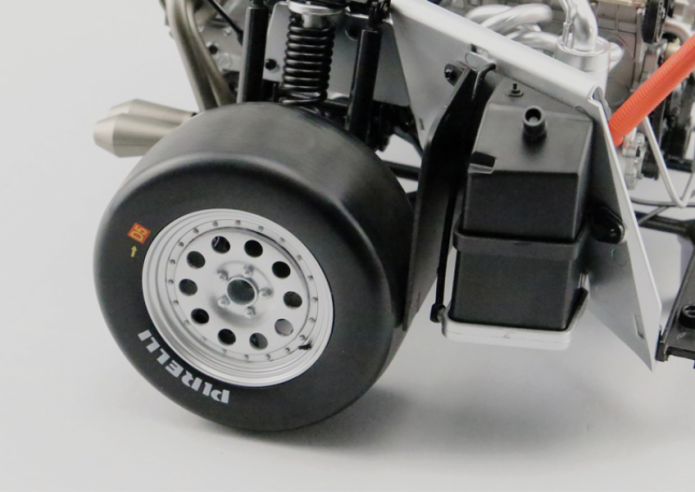
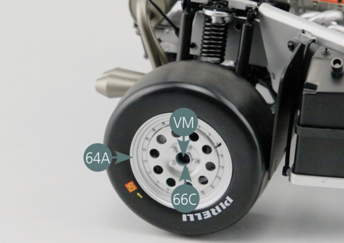
Positionner la roue arrière sur le moyeu arrière droit 46A.
Positionner la rondelle 66C au centre de la jante de roue extérieure 64A.
Fixer la roue arrière sur le moyeu arrière droit 46A avec une vis VM.
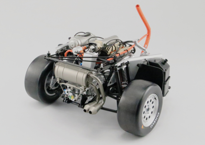
Vue générale
Position washer (66C) into the center of the outer wheel rim (64A). Secure the rear wheel to the right rear hub (46A) with a VM screw.
Kit 67 - Plancher
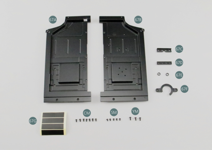
Parts of kit

Etape 1
- 67F Speaker bracket
- 67G Cable Tape
- Screw CM M 2.0 x 4 mm (x 7)
- Screw SM M 1.7 x 3 mm (x 5)
- Screw YM M 1.7 x 4 mm (x 3)
Positionner le plancher gauche 67A et le plancher droit 67B côte à côte et les relier avec le joint arrière 67C fixé par deux vis CM.
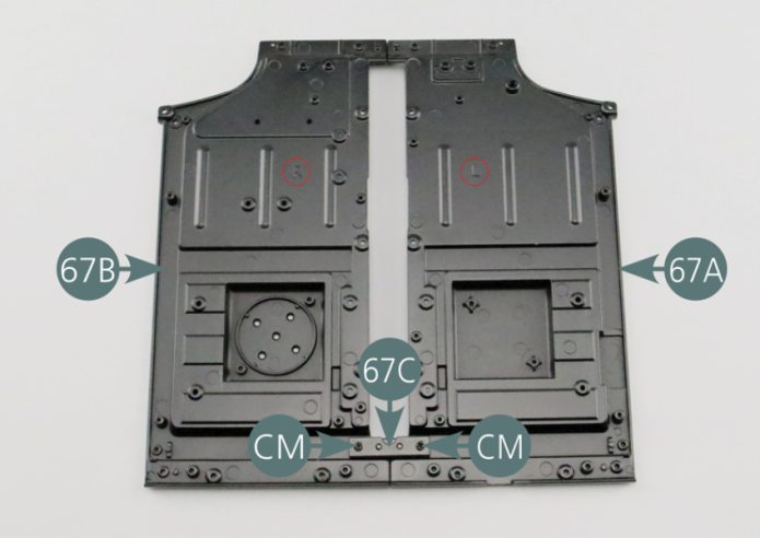
Etape 2
Place the left floor panel (67A) and the right floor panel (67B) side by side and connect them with the rear joint (67C)and secure with two CM screws.

Relier ensuite les deux planchers gauche 67A et droit 67B avec le joint avant 67D fixé par deux vis CM.
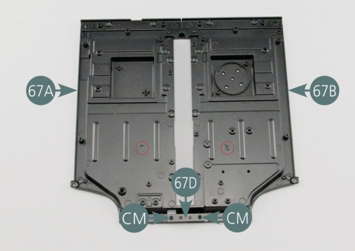
Etape 3
Then connect the left (67A) and right (67B) floor panels with the front joint (67D) and secure by two CM screws.

Débrancher avec précaution le haut-parleur 18A, le compartiment de piles 18B, les câbles des phares 18D et le groupement de câbles des feux arrière 19A du circuit imprimé 18C.
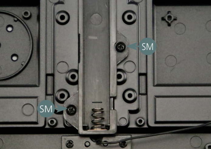
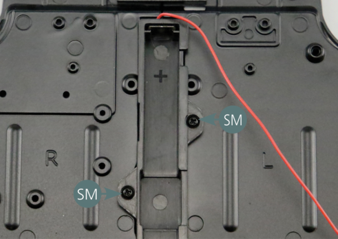
Positionner le compartiment de piles 18B sur le plancher et le fixer avec quatre vis SM.
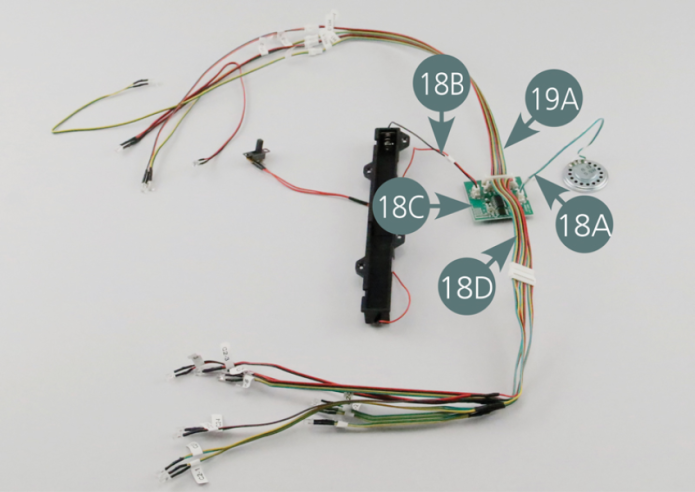
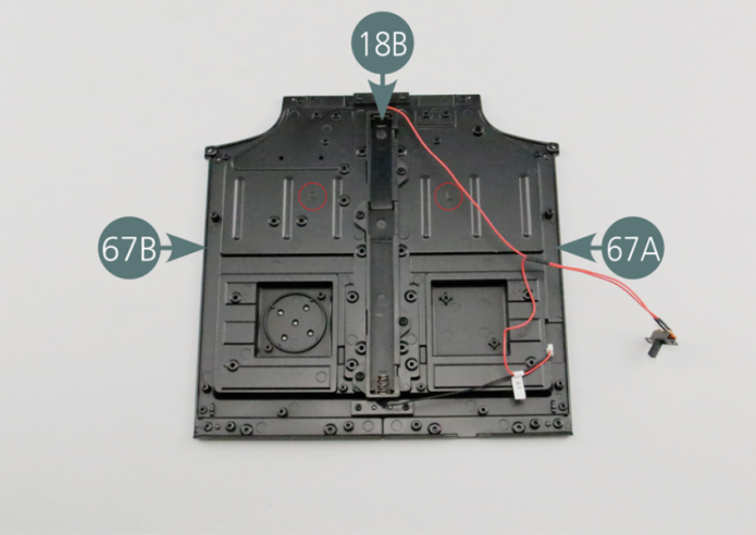
Carefully disconnect the speaker (18A), battery compartment (18B), headlight cables (18D), and taillight wire bundle (19A) from the PCB (18C). Position the battery compartment (18B) on the floor and secure with four SM screws.
Etape 4


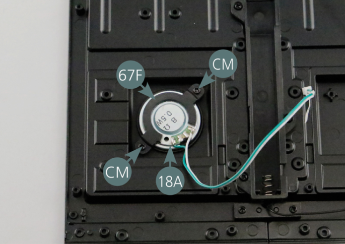
Positionner le haut-parleur 18A sur le plancher droit 67B puis le fixer avec le support de haut-parleur 67F à l’aide de deux vis CM.
Etape 5
Place the speaker (18A) on the right floor panel (67B) then secure it with the speaker bracket (67F) using two CM screws.

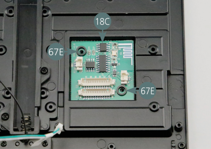
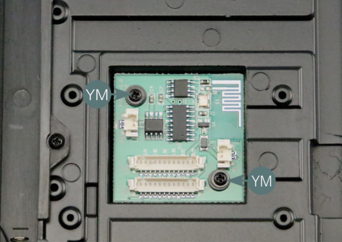
Positionner le circuit imprimé 18C sur le plancher gauche 67A, puis le fixer avec deux vis YM passées dans les deux rondelles 67E.
Etape 6
Position the PCB (18C) on the left floor panel (67A), then secure it with two YM screws that need to be passed through the two washers (67E).


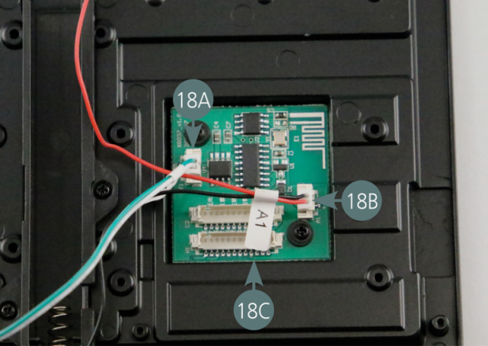
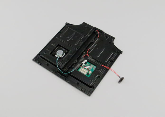
Rebrancher les câbles du haut-parleur 18A et du compartiment de piles 18B sur le circuit imprimé 18C.
Etape 7
Reconnect the cables of the speaker (18A) and battery compartment (18B) to the PCB (18C).

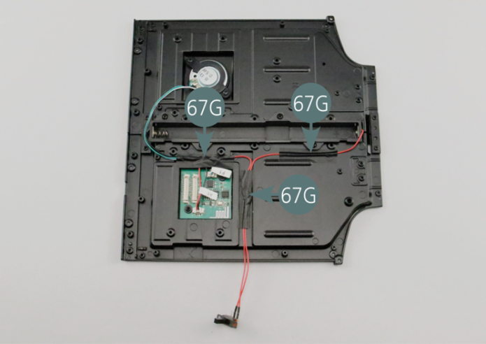
Fixer trois morceaux de ruban adhésif 67G sur les câbles comme indiqué sur la photo.
Vue générale
Attach three pieces of tape (67G) to the cables as indicated in the picture.

Kit 68 - Extincteurs
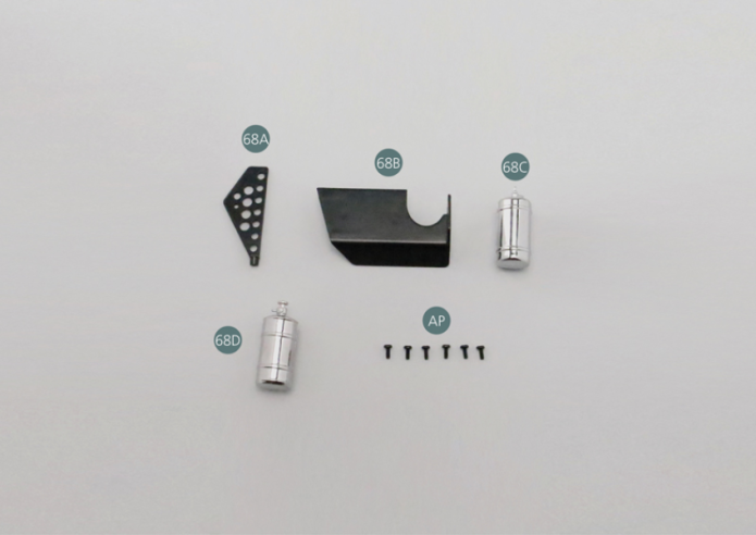
Parts of kit
Etape 1
- 68D Fire extinguisher #2
- Screw AP P 1.7 x 4 mm (x 6)
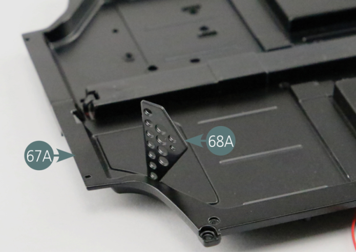
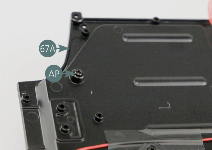
Positionner la plaque gauche 68A sur le plancher gauche 67A et la fixer par en dessous avec une vis AP.

Etape 2
Place the left plate (68A) on the left floor panel (67A) and secure it from below with an AP screw.

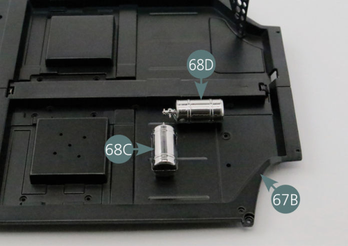
Positionner les deux extincteurs 68C et 68D sur le plancher droit 67B comme indiqué et les fixer par en dessous avec quatre vis AP.

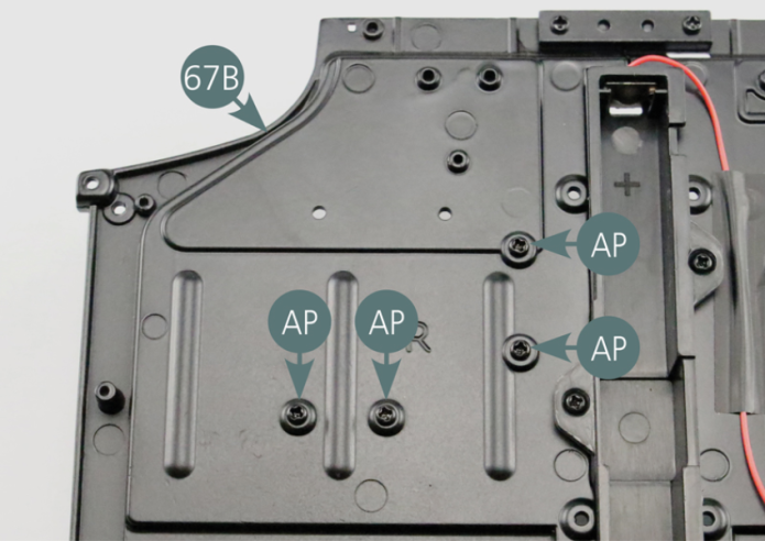
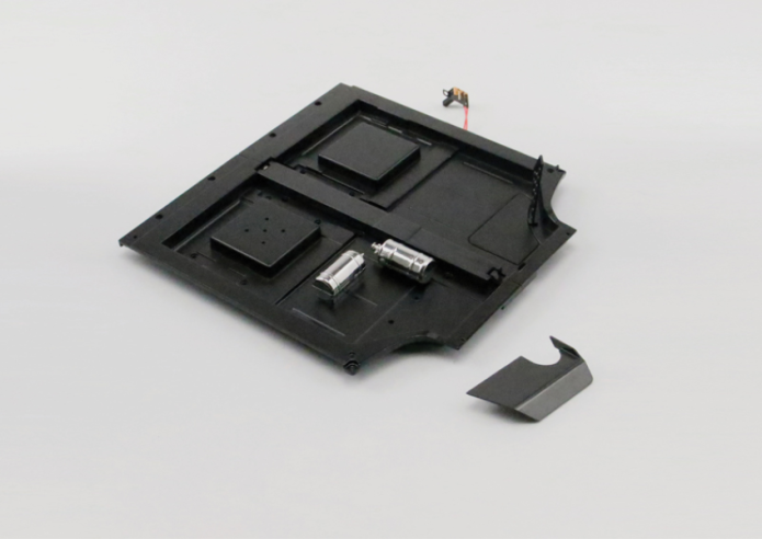
Vue générale
Position the two fire extinguishers (68C&68D) on the right floor panel (67B) as per picture and secure from below with four AP screws.