English
 français
 Deutsch
 español
 italiano
 português


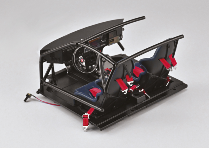
Box 22
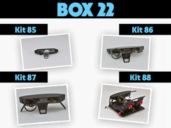
Kit 85 - Panneau du tableau de bord (5)
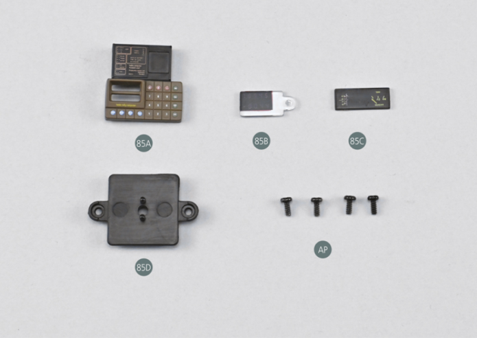
Parts of kit
- 85A Panneau d’ordinateur de bord
- 85B Indicateurs de l’ordinateur de bord
- 85C Instruments inférieurs du tableau de bord central
- 85D Cache arrière des instruments centraux inférieurs
- AP Vis P 1,7 x 4 mm (x 4)
Etape 1
- 85D Rear cover for lower central instruments
- Screw AP P 1.7 x 4 mm (x 4)

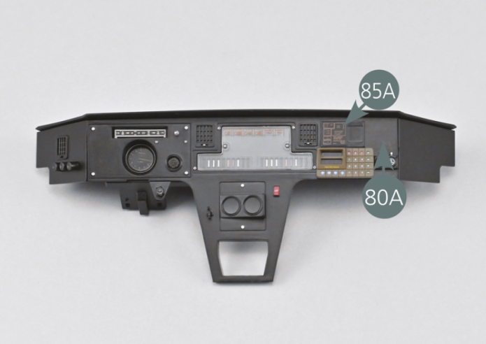
Prendre le panneau d’ordinateur de bord 85A et le placer face interne tournée vers le haut.
Positionner les indicateurs de l’ordinateur 85B sur le panneau 85A comme indiqué sur la photo.
Positionner le panneau d’ordinateur de bord 85A sur l’avant droit du panneau du tableau de bord 80A.
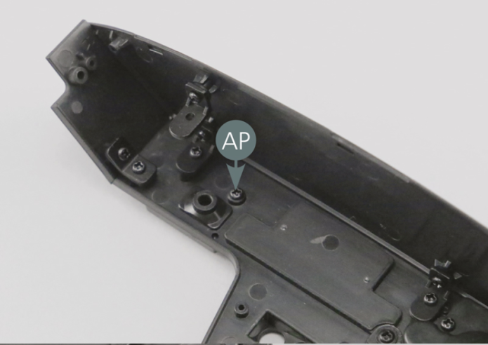
Fixer le panneau d’ordinateur 85A depuis l’arrière du tableau de bord avec une vis AP.
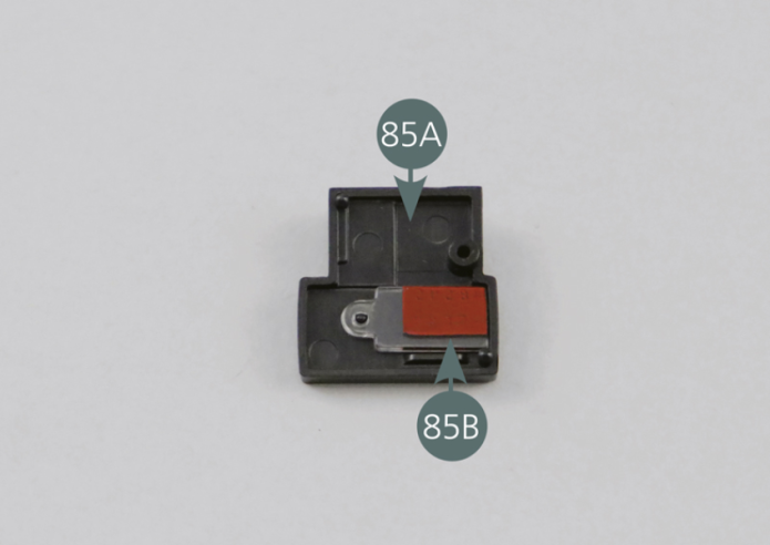

Take the on-board computer panel (85A) and place it face up. Position the computer indicators (85B) on the panel (85A) as shown in the photo. Position the on-board computer panel (85A) on the right front of the dashboard panel (80A). Secure the computer panel (85A) with an AP screw from the rear of the dashboard.

Etape 2
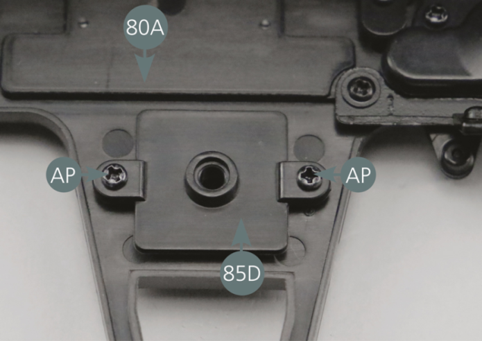
Engager les instruments inférieurs 85C dans le logement rectangulaire sur la face interne du panneau du tableau de bord 80A. Vérifier l’orientation correcte des instruments 85C comme indiqué sur la photo.
Positionner le cache arrière 85D au-dessus des instruments inférieurs 85C et le fixer avec deux vis AP.

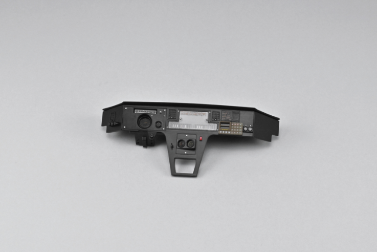
Vue générale
Insert the lower instruments (85C) into the rectangular recess on the inside of the dashboard panel (80A). Check the correct orientation of the instruments (85C) as illustrated. Position the rear cover (85D) over the lower instruments (85C) and secure with two AP screws.


Kit 86 - Volant de direction
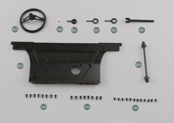
Parts of kit
Etape 1
- 86G Firewall (new)
- 86H Intermediate shaft (new)
- Screw AM M 1.7 x 4 mm (x 8)
- Screw CM M 2.0 x 4 mm (x 8)
- Screw SM M 1.7 x 3 mm (x 12)
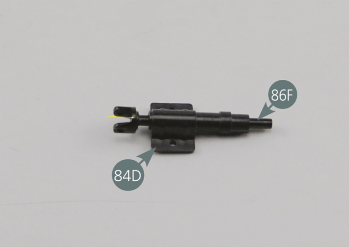
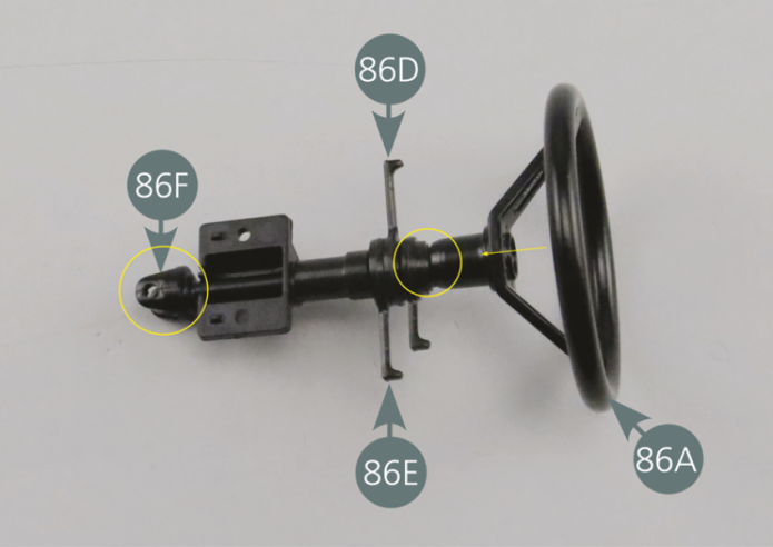
Engager la colonne de direction 86F dans le support 84D comme indiqué par la flèche jaune.
Placer la commande des phares 86E sur la colonne de direction comme indiqué sur la photo.

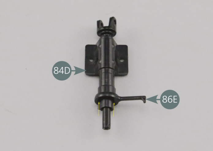
Engage the steering column (86F) in the support (84D) as shown by the yellow arrow. Place the headlight control (86E) on the steering column as shown in the photo.
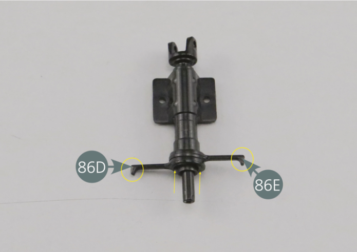
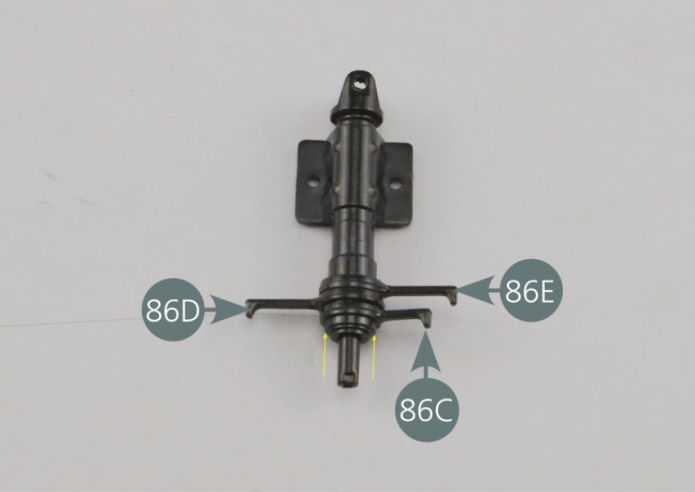
Placer ensuite la commande du lave-glace 86D, du côté opposé à la commande 86E. Placer enfin l’indicateur de direction 86C sur la colonne, du même côté que la commande 86E, comme indiqué sur la photo.

Etape 2
Then place the windscreen washer control (86D) opposite the control (86E). Finally, place the direction indicator (86C) on the column, on the same side as the control (86E), as shown in the photo.

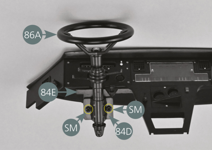
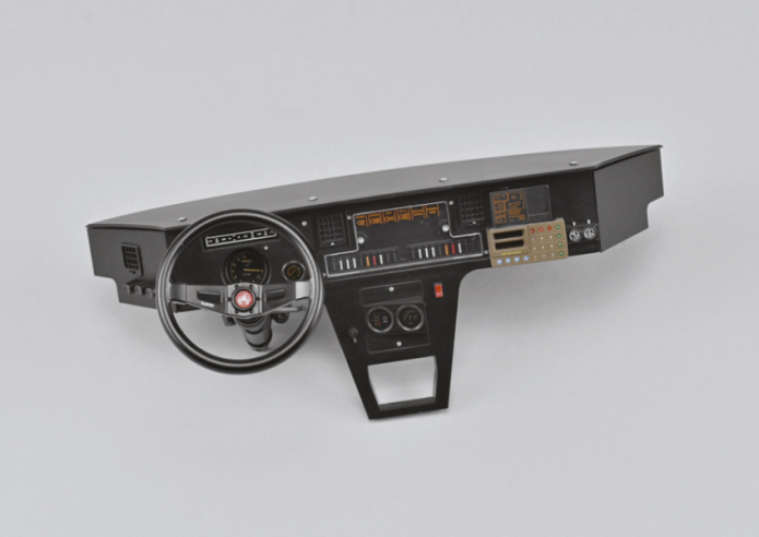
Positionner le volant 86A sur la colonne de direction 86 F, puis le fixer avec une vis SM à l’extrémité et au centre de la colonne.
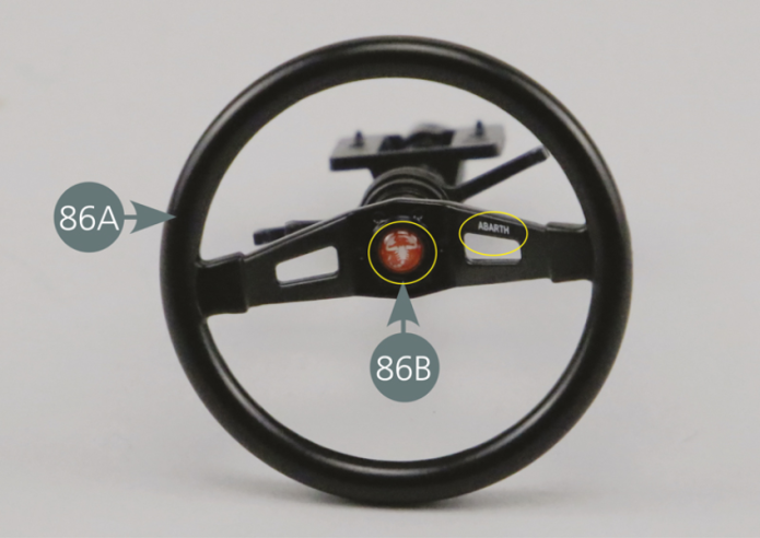
Détacher l’écusson autocollant 86B de son support papier et le positionner au centre du volant, en veillant au bon positionnement du dessin de scorpion du logo.
Veiller également à ce que le nom ABARTH soit bien positionné sur la branche droite, comme indiqué sur la photo.
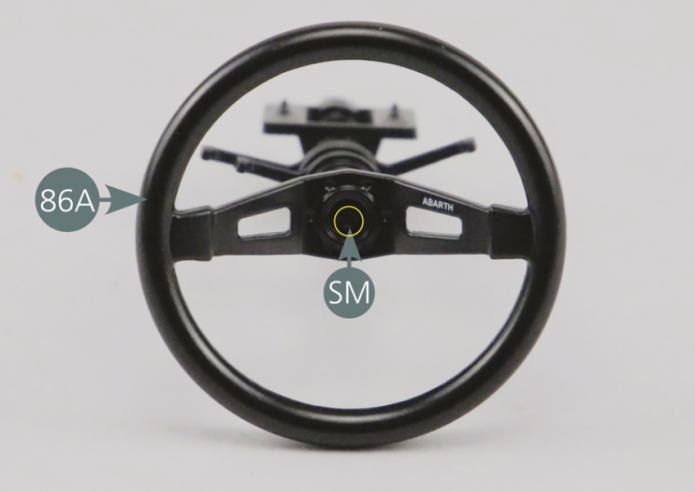
Position the steering wheel (86A) on the steering column (86F), then secure it with an SM screw on the end and in the centre of the column. Detach the self-adhesive emblem (86B) from its paper backing and position it at the centre of the steering wheel, making sure that the scorpion design of the logo is correctly positioned. Also ensure that the name ABARTH is correctly positioned and on the right-hand side, as shown in the photo.
Etape 3


Positionner l’assemblage de la colonne de direction sur la plaque inférieure du tableau de bord 84E et le fixer avec deux vis SM.

Etape 4
Position the steering column assembly on the lower dashboard panel (84E) and secure with two SM screws.
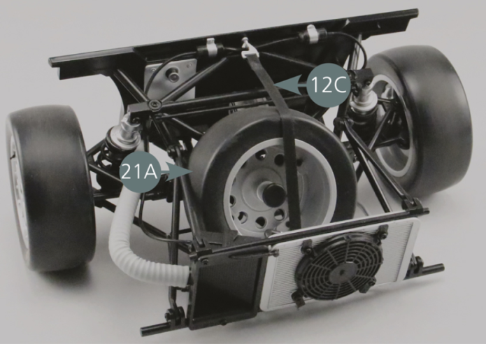
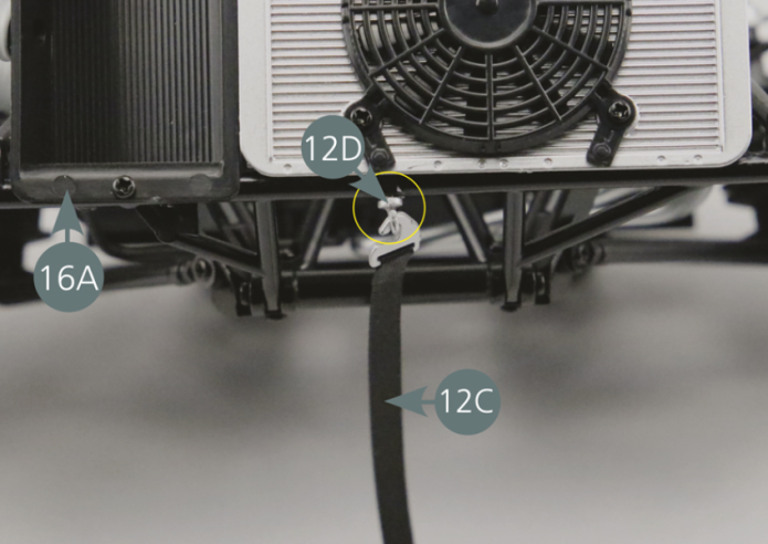
Reprendre le châssis avant assemblé lors des étapes précédentes. Détacher la sangle de roue de secours 12C et retirer la roue de secours 21A.


Etape 5
Return to the front frame assembled in the previous steps. Detach the spare wheel strap (12C) and remove the spare wheel (21A).
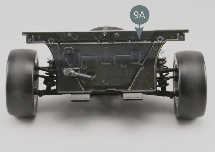
Il s’agit maintenant de remplacer l’ancienne cloison pare-feu 9A par la nouvelle pièce 86G.
Pour commencer, retirer toutes les vis et les éléments entourés en jaune sur la photo : les vis supérieures, les deux supports 9B aux extrémités, les vis centrales du support de batterie et les vis du pédalier. Retirer ce dernier.
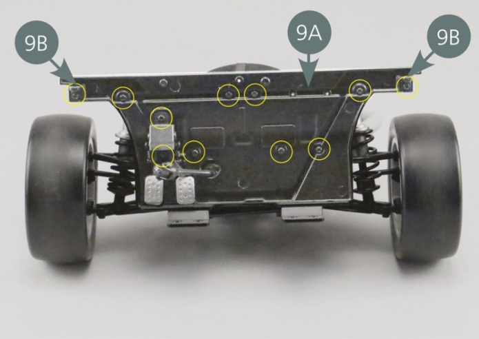
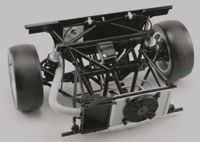
Sur la deuxième photo, on peut constater que la cloison 9A ne dispose plus des vis, supports 9B et pédalier.
Etape 6
In the second photo, you can see that the firewall (9A) no longer contains the screws, brackets (9B) and crankset.

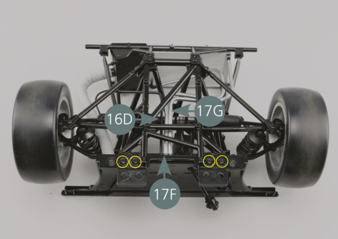
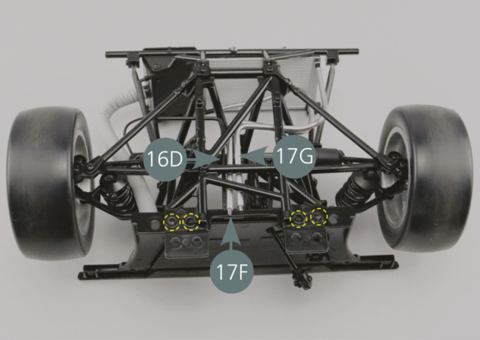
Retourner le châssis avant. Retirer les 4 vis (entourées en jaune) de la cloison pare-feu 9A et débrancher la conduite d’huile 16D ainsi que les conduites 17F et 17G.


Etape 7
Flip the front frame over. Remove the 4 screws (circled in yellow) from the firewall (9A) and disconnect the oil pipe (16D) and the pipes (17F&17G).
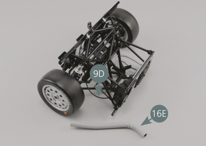
Déconnecter le tuyau d’évacuation d’air 16E et la durite d’huile 9D.
Etape 8
Disconnect the air exhaust hose (16E) and the oil pipe (9D).

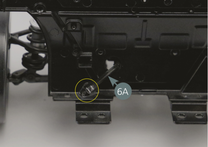
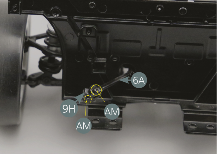
Détacher le joint universel 9H de l’arbre intermédiaire 6A, ainsi que les deux vis AM entourées en jaune.
Le joint universel 9H sera réutilisé plus tard.

Etape 9
Detach the universal joint (9H) from the intermediate shaft (6A), as well as the two AM screws, circled in yellow. The universal joint (9H) will be reused in a later stage.

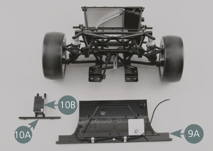
Il est maintenant possible de retirer l’ancienne cloison pare-feu 9A, ainsi que la batterie 10B et son support 10A.

Etape 10
It is now possible to remove the old firewall (9A), as well as the battery (10B) and its carrier (10A).
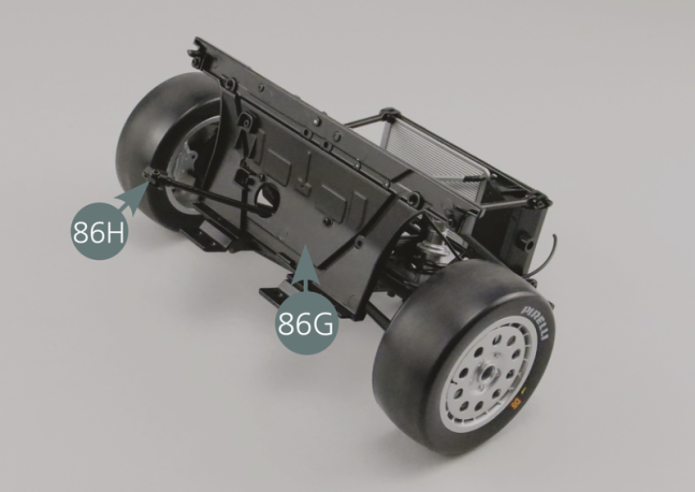
Dévisser les vis SM (flèches et cercles jaunes) et retirer l’arbre intermédiaire 6A. La pièce 6A sera remplacée par la pièce 86H fournie dans ce numéro.
Fixer le joint universel 9H retiré à l’étape 08 sur le nouvel arbre intermédiaire 86H à l’aide de deux vis AM.
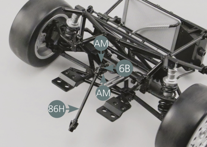
Fixer ensuite l’extrémité opposée de l’arbre 86H sur le joint universel 6B à l’aide de deux vis AM.
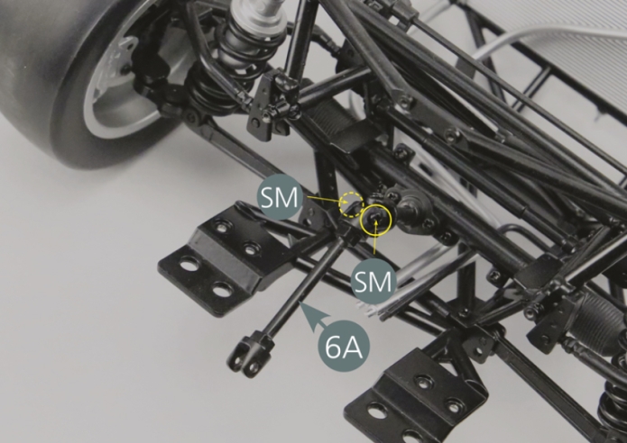
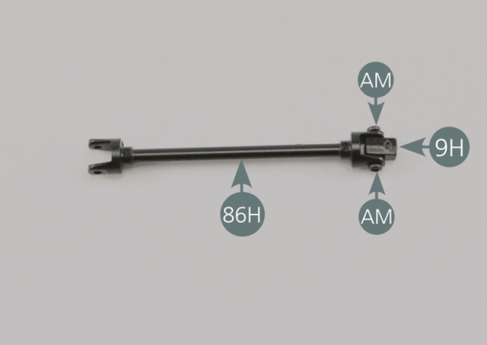
Unscrew the SM screws (see yellow arrows and circles) and remove the intermediate shaft (6A). Part 6A will be replaced by part 86H provided with this issue. Secure the universal joint (9H) removed in step 08 to the new intermediate shaft (86H) using two AM screws. Then secure the opposite end of the shaft (86H) to the universal joint (6B) using two AM screws.
Etape 11


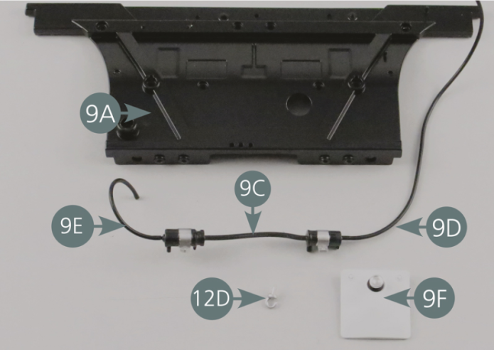
Détacher avec précaution de la cloison pare-feu 9A l’ensemble durites, filtre et pompe à huile (pièces 9C, 9D et 9E), ainsi que le réservoir de liquide lave-glace 9F et le crochet 12D.
Conserver soigneusement ces pièces.

Etape 12
Carefully detach the hose, oil filter and oil pump (parts 9C, 9D and 9E), as well as the washer fluid reservoir (9F) and hook (12D) from the firewall (9A). Keep these parts in a safe place.
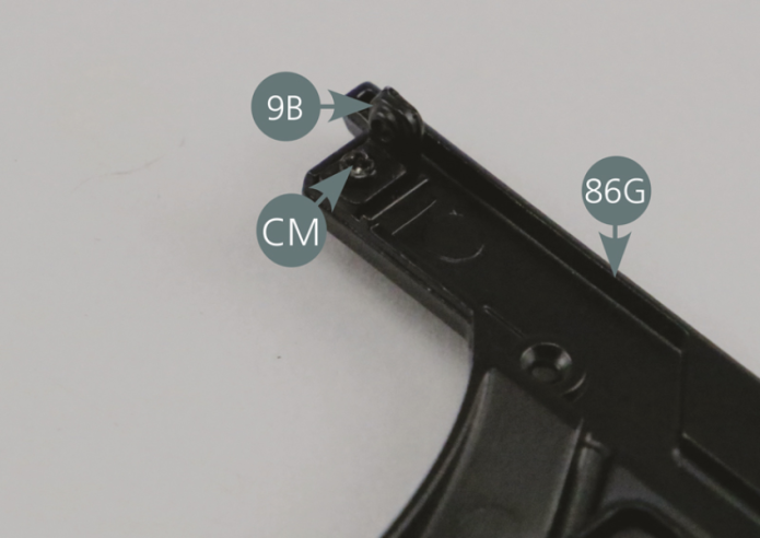
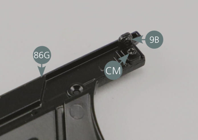
Fixer les deux supports 9B (détachés précédemment) sur les extrémités supérieures de la nouvelle cloison pare-feu 86G avec deux vis CM.

Etape 13
Secure the two brackets (9B) (previously detached) to the upper ends of the new firewall (86G) with two CM screws.

Il reste maintenant à positionner les éléments précédemment détachés de l’ancienne cloison pare-feu 9A sur la nouvelle cloison 86G.
Commencer par l’ensemble durites, filtre et pompe à huile (pièces 9C, 9D et 9E), puis le réservoir de liquide lave-glace 9F et le crochet 12D.
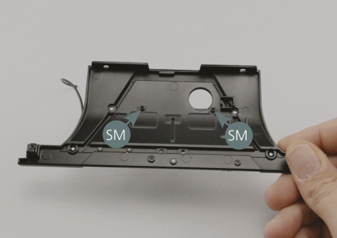
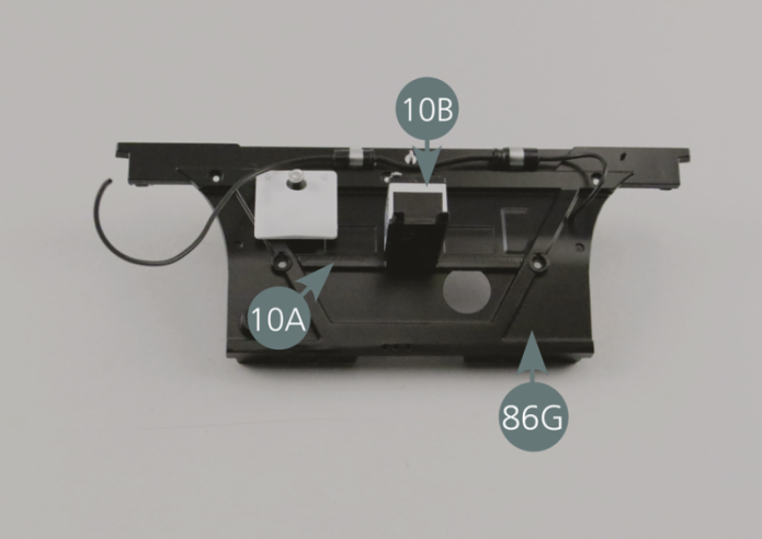
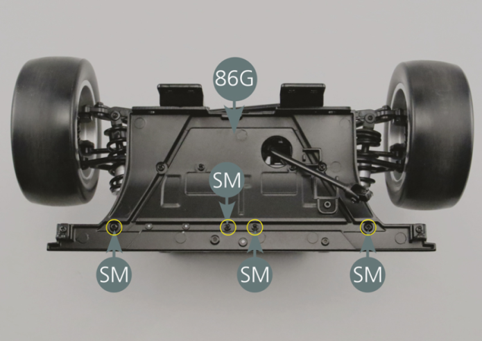
Positionner ensuite le support de batterie 10A (avec la batterie 10B), puis le fixer avec deux vis SM par l’arrière de la cloison 86G.
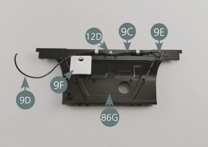

All that now remains is to place the elements previously detached from the old firewall (9A) on the new wall (86G). Start with the hose, filter and oil pump assembly (parts 9C, 9D and 9E), then the windshield washer fluid reservoir (9F) and the hook (12D). Then place the battery holder (10A) (including battery 10B), and secure with two SM screws from the rear of the wall (86G).
Etape 14

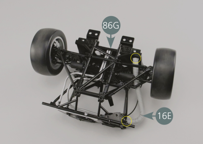
Positionner la nouvelle cloison avant 86G sur le châssis avant. Glisser l’arbre intermédiaire 86H dans le trou prévu à cet effet.
Retourner l’ensemble et fixer la cloison 86H sur le cadre inférieur 5A avec quatre vis CM.
Brancher ensuite la conduite d’huile 16D, ainsi que les conduites 17F et 17G dans les orifices prévus sur la cloison avant (indiqués par un ovale blanc : photo ci-dessous).
Terminer la fixation de la nouvelle cloison 86G sur le châssis avant avec deux vis AM et quatre vis SM (indiquées par des cercles jaunes).
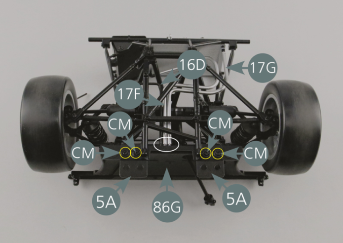
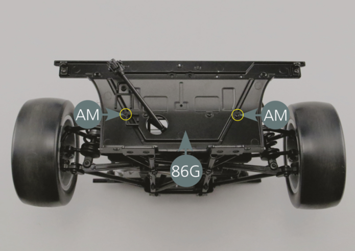
Finish securing the new firewall (86G) to the front chassis with two AM screws and four SM screws (see the yellow circles).

Etape 15

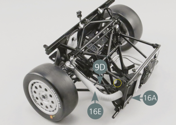
Positionner le pédalier 20D sur la cloison avant 86G et le fixer avec une vis SM.
Reconnecter le tuyau d’évacuation d’air 16E et la durite d’huile 9D au radiateur 16A comme indiqué par les cercles jaunes (photos ci-dessus et ci-contre).
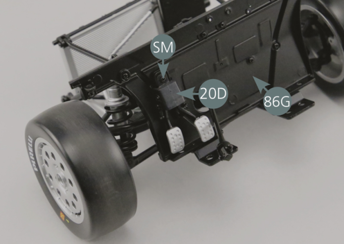

Position the crankset (20D) on the front firewall (86G) and secure it with an SM screw. Reconnect the air exhaust pipe (16E) and the oil hose (9D) to the radiator (16A) as indicated by the yellow circles (photos above and opposite).

Etape 16
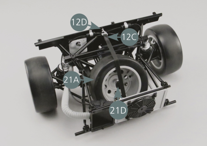
Accrocher la sangle de la roue de secours 12C au crochet inférieur 12D situé sur le cadre inférieur 5A.
Passer ensuite la sangle à l’intérieur du cadre, puis positionner la roue de secours 21A et accrocher la sangle 12C au crochet supérieur 12D.

Vue générale
Hook the spare tire strap (12C) to the lower hook (12D) located on the lower frame (5A). Then pass the strap inside the frame, and subsequently place the spare wheel (21A) and hook the strap (12C) to the upper hook (12D).

Kit 87 - Barre de support du tableau de bord
Parts of kit
Etape 1
- Screw SM M 1.7 x 3 mm (x 3)
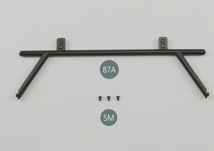
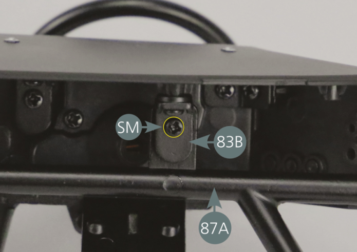
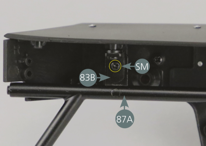
Positionner la barre de support 87A sur l’arrière du panneau du tableau de bord 80A.
Faire correspondre les trous de la barre 87A avec les attaches 83B, puis la fixer avec deux vis SM comme indiqué sur les photos (cercles jaunes).
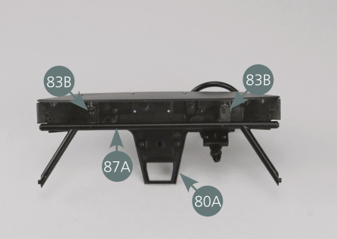

Place the support bar (87A) on the rear of the dashboard panel (80A). Match the openings of the bar (87A) with the fasteners (83B), then secure with two SM screws as shown in the photos (yellow circles).
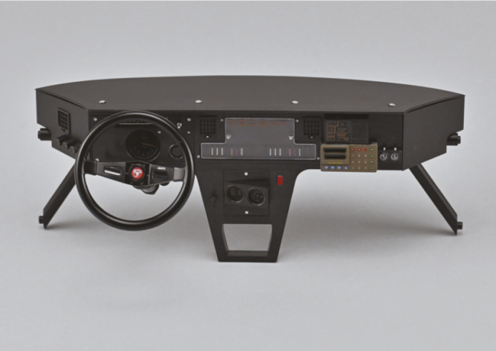
Vue générale

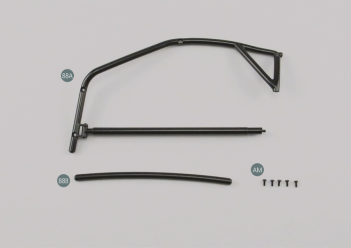
Kit 88 - Arceau cage de sécurité (1)
Parts of kit
Etape 1
- Screw AM M 1.7 x 4 mm (x 5)
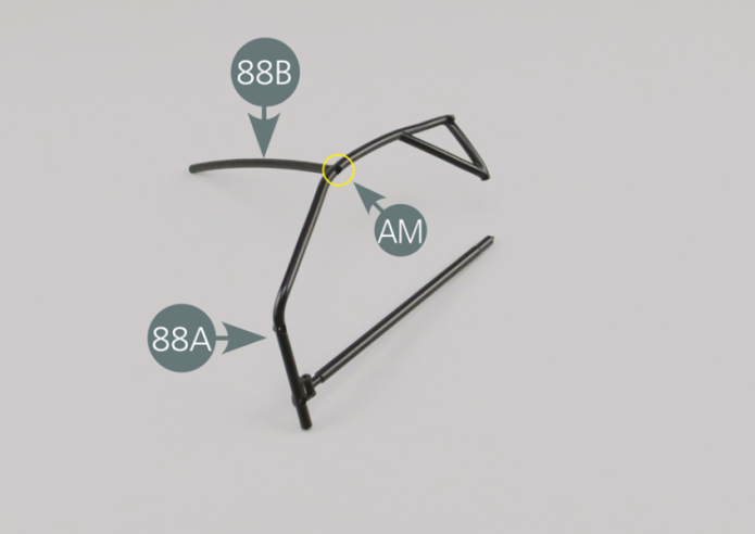
Positionner l’extrémité de la barre supérieure de l’arceau 88B dans le logement prévu sur la cage gauche 88A et la fixer avec une vis AM.
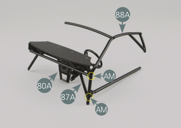
Positionner le panneau de tableau de bord 80A et la barre de support 87A sur la cage gauche de l’arceau de sécurité 88A et le fixer avec une vis AM.
Etape 2
Place the end of the upper bar of the roll cage (88B) in the slot provided on the left roll cage (88A) and secure it with an AM screw. Position the dashboard panel (80A) and the support bar (87A) on the left safety roll cage (88A) and secure with an AM screw.


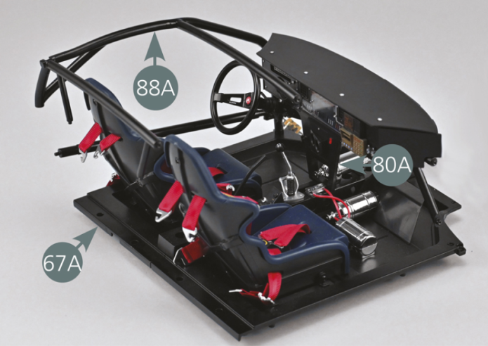
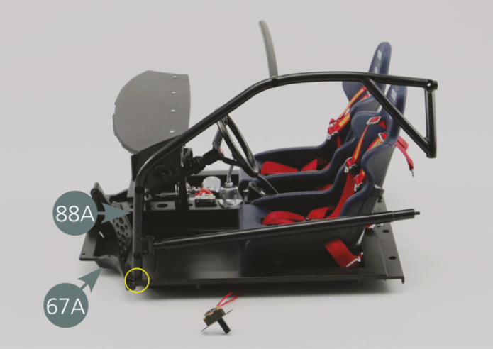
Positionner la cage gauche de l’arceau de sécurité 88A et le panneau du tableau de bord 80A sur le plancher gauche 67A.
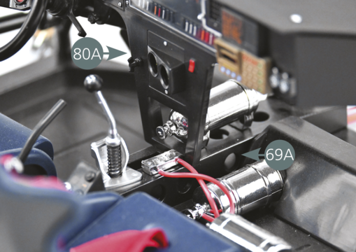
Veiller à positionner correctement le panneau de tableau de bord 80A sur le tunnel central 69A, comme indiqué sur les photos.
Etape 3
Position the left rollbar safety cage (88A) and the dashboard panel (80A) on the left floor panel (67A). Be sure to correctly position the dashboard panel (80A) on the center tunnel (69A) as shown in the photos.


Insérer l’extrémité inférieure de la cage gauche de l’arceau 88A dans le trou du plancher gauche 67A (indiqué en jaune).
Retourner l’ensemble et fixer la cage 88A au plancher 67A avec une vis AM.
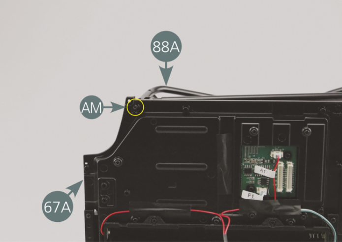
Vue générale
Insert the bottom end of the left roll bar safety cage (88A) into the slot in the left floor panel (67A) (indicated in yellow). Turn the assembly over and secure the cage (88A) to the floor panel (67A) with an AM screw.