English
 français
 Deutsch
 español
 italiano
 português


Box 28
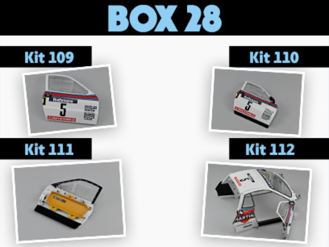
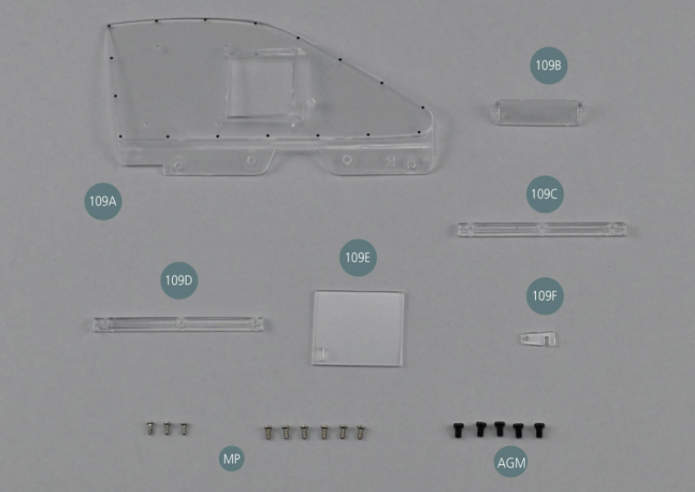
Kit 109 - Vitre de portière droite
Parts of kit
- 109A Vitre droite
- 109B Déflecteur de vitre
- 109C Guide inférieur
- 109D Guide supérieur
- 109E Fenêtre d’aération coulissante
- 109F Loquet de fenêtre
- MP Vis M 1,2 x 3 mm (x 9)
- AGM Vis M 2,0 x 3 mm (x 5)

Etape 1
- 109E Slidable ventilation window
- 109F Window Latch
- Screw MP M 1.2 x 3 mm (x 9)
- Screw AGM M 2.0 x 3 mm (x 5)
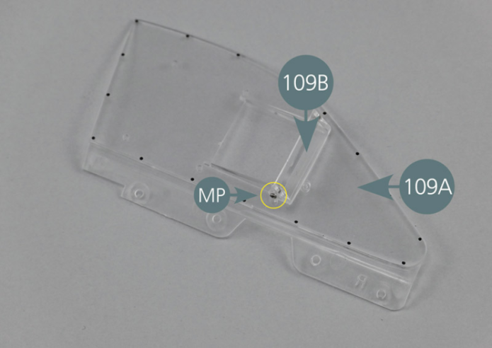
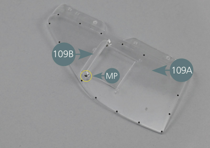
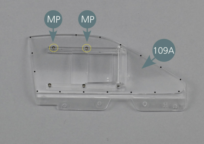
Positionner le déflecteur 109B sur l’extérieur de la vitre 109A et le fixer avec deux vis MP comme indiqué.


Etape 2
Position the deflector (109B) on the outside of the window (109A) and secure it with two MP screws as shown.
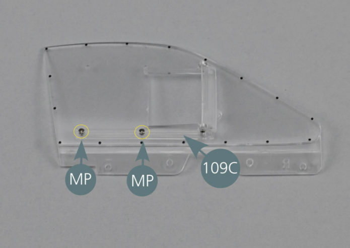
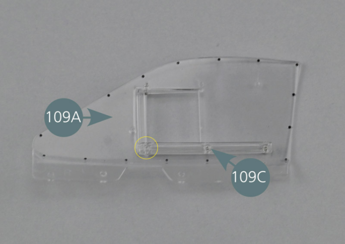
Positionner le guide inférieur 109C sur la face intérieure de la vitre 109A en veillant à ce que la rainure soit orientée vers le haut comme indiqué sur la photo.
Centrer la goupille située sur la droite de la fenêtre dans le trou du guide inférieur comme indiqué (cercle jaune ci-dessous).
Tout en le maintenant en position, fixer le guide 109C depuis l’extérieur de la vitre 109A avec deux vis MP.
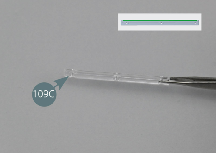

Place the lower window guide (109C) on the inside of the window (109A) ensuring that the groove is facing upwards as per picture. Center the pin located on the right of the window in the opening of the lower window guide as shown (yellow circle). While holding it in position, secure the guide (109C) from the outside of the window (109A) with two MP screws.
Etape 3

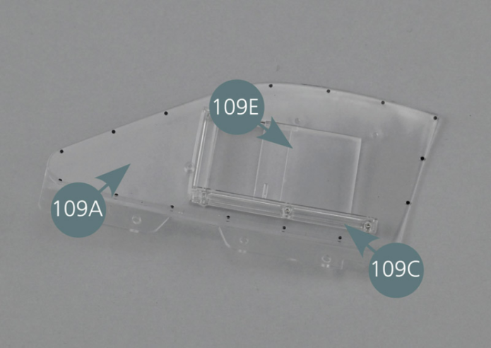
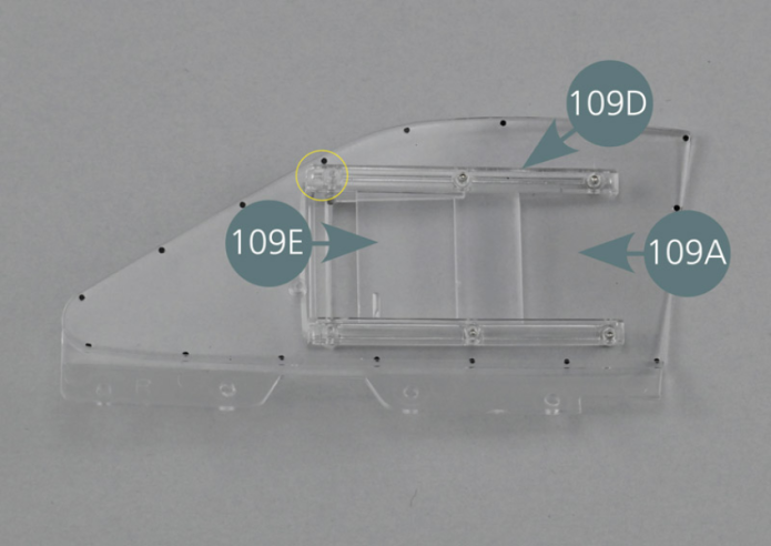
Positionner la fenêtre coulissante 109E dans la rainure du guide inférieur 109C à l’intérieur de la vitre 109A. Vérifier que la poignée est bien orientée vers l’avant de la fenêtre.

Etape 4
Position the sliding window (109E) in the groove of the lower window guide (109C) inside the window (109A). Check that the handle is oriented towards the front of the window.
Positionner le guide supérieur 109D sur la face intérieure de la vitre 109A en veillant à ce que la rainure soit orientée vers le bas comme indiqué sur la photo.
Centrer la goupille située sur la droite de la fenêtre dans le trou du guide supérieur comme indiqué (cercle jaune ci-dessous).
Tout en maintenant le guide et la fenêtre en position, fixer le guide 109D depuis l’extérieur de la vitre 109A avec deux vis MP.
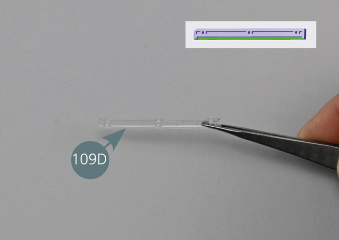

Position the upper window guide (109D) on the inside of the window (109A) ensuring that the groove is facing downwards as per picture. Center the pin located on the right of the window into the opening of the upper window guide as shown (yellow circle). While holding the guide and the window in position, secure the guide (109D) from the outside of the window (109A) with two MP screws.
Etape 5

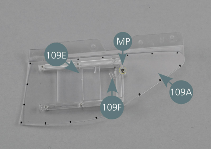
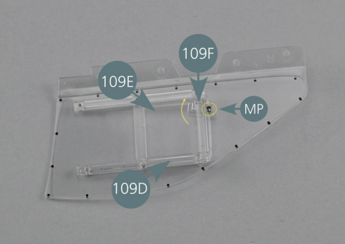
Positionner le loquet 109F dans l’ouverture de la poignée de la fenêtre coulissante 109E et le fixer avec une vis MP.
Vérifier que le loquet 109F tourne aisément et qu’il bloque correctement la fenêtre coulissante 109E. Si besoin serrer ou desserrer la vis pour un bon ajustement.
Etape 6
Position the latch (109F) into the opening of the handle of the sliding window (109E) and secure with an MP screw. Check that the latch (109F) turns easily and that it locks the sliding window (109E) correctly. If necessary, tighten or loosen the screw for a proper fit.


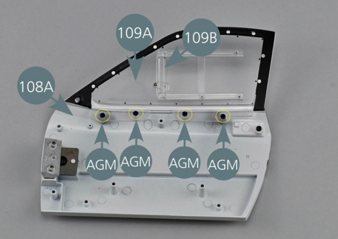
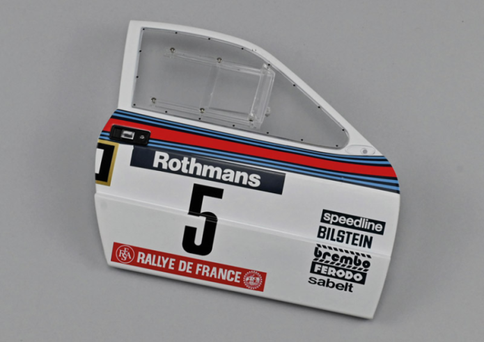
Positionner la vitre droite 109A sur la face intérieure de la portière droite 108A avec le déflecteur orienté vers l’extérieur. Fixer la vitre 109A sur la portière avec quatre vis AGM.
Vue générale
Place the right window (109A) on the inside of the right door (108A), with the deflector facing outwards. Secure the window (109A) to the left door with four AGM screws.
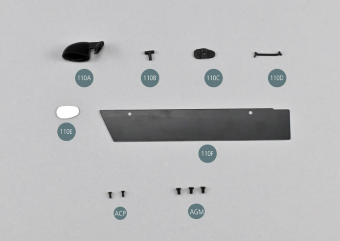
Kit 110 - Rétroviseur droit
Parts of kit

Etape 1
- 110E Rearview mirror
- 110F Door sill protection
- Screw ACP P 1.4 x 3 mm (x 2)
- Screw AGM M 2.0 x 3 mm (x 3)
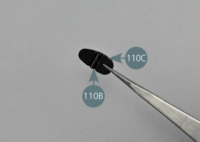
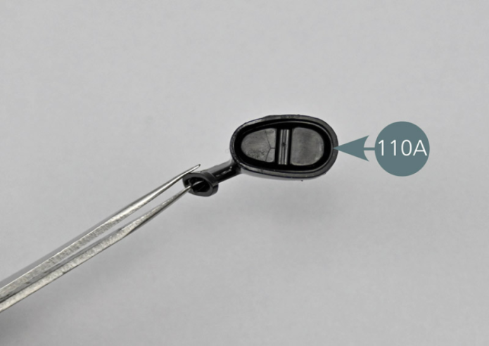
Placer le rétroviseur 110A, l’articulation 110B et le support 110C sur la surface de travail.
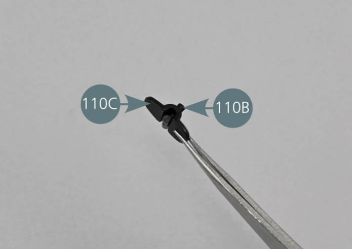
Insérer la goupille de l’articulation 110B dans le trou situé à la base du support de rétroviseur 110C, comme indiqué sur les photos.
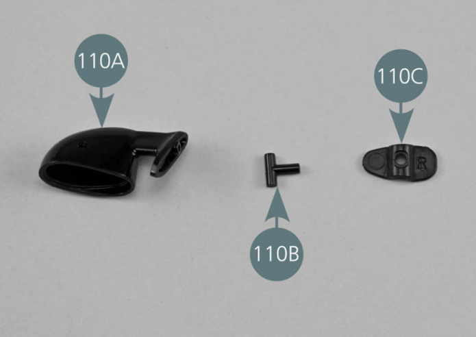

Place the mirror (110A), the joint (110B) and the support (110C) on the work surface.
Insert the pin of the joint (110B) into the opening located at the base of the mirror support (110C), as shown in the photos.
Etape 2

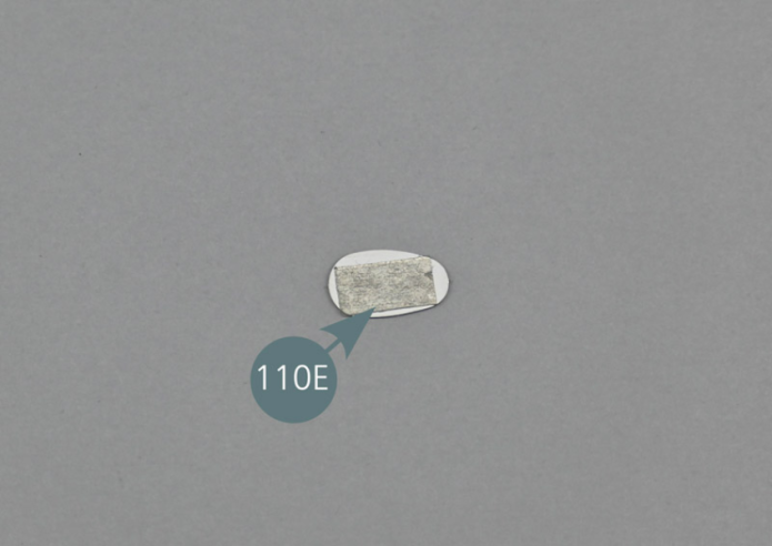
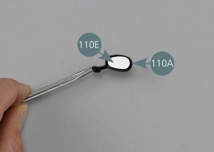
Positionner l’assemblage réalisé dans le rétroviseur 110A. Retirez le film protecteur de l’adhésif double-face situé sur le miroir 110E, puis positionner le miroir 110E sur le support 110C en le pressant et en veillant à faire correspondre les formes.
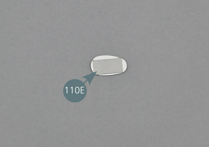
Position the assembly made in step 1 in the rearview mirror (110A).
Remove the protective film from the double-sided adhesive that is on the mirror (110E), then position the mirror (110E) on the support (110C) by pressing it and ensuring that the shapes match.
Etape 3


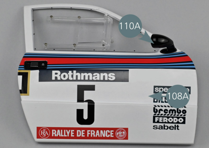
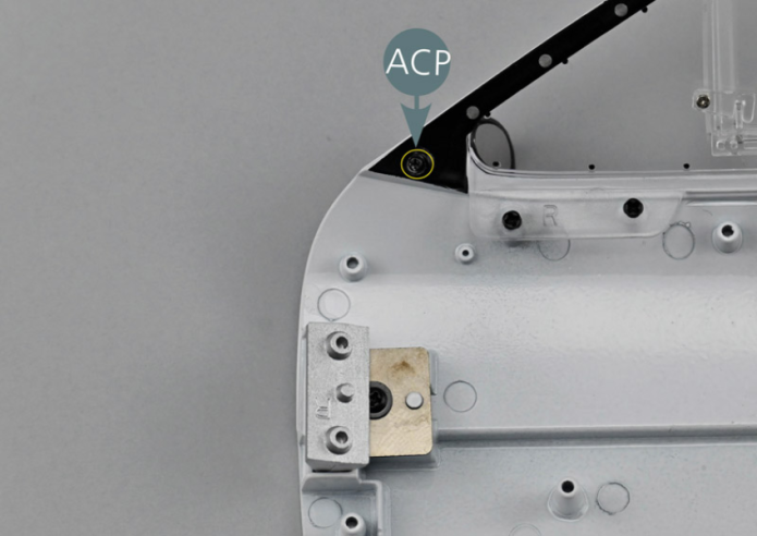
Positionner le rétroviseur extérieur droit 110A sur la portière droite 108A, puis le fixer depuis l’intérieur avec une vis ACP.
Etape 4
Place the right exterior mirror (110A) on the right door (108A), then secure it from the inside with an ACP screw.


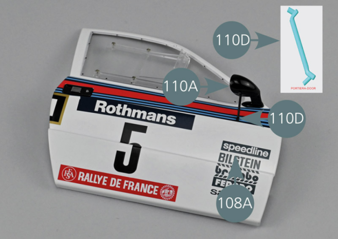
Positionner la tige de soutien 110D en respectant le sens comme indiqué sur la photo de détail.
L’un des tétons s’insère dans le trou prévu sur la portière 108A et l’autre dans le trou situé à la base du rétroviseur 110A.
Etape 5
Position the support rod (110D) respecting the direction as indicated in the detail photo. One of the pins to be inserted into the opening provided on the door (108A) and the other into the opening located at the base of the rearview mirror (110A).

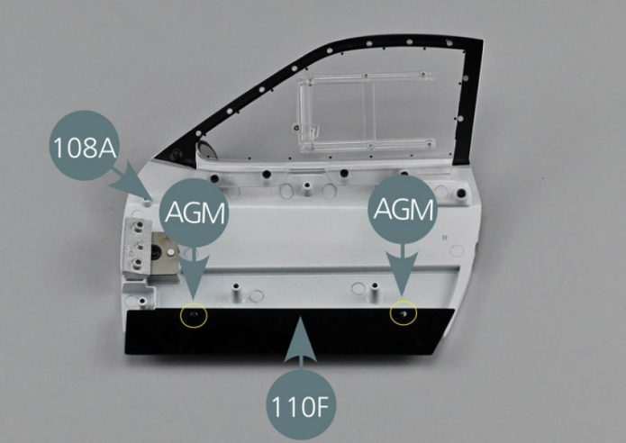
Positionner la protection 110F sur la base de la portière 108A, côté intérieur. Aligner les deux trous de la protection 110 F avec les deux supports de la portière 108A. Fixer la protection de bas de portière 110F avec deux vis AGM (cercles jaunes).
Vue générale
Position the sill protection (110F) on the base of the door (108A), interior side. Align the two openings of the sill protection (110F) with the two supports of the door (108A). Secure the door sill protection (110F) with two AGM screws (yellow circles).

Kit 111 - Habillage intérieur de portière droite #A
Parts of kit
Etape 1
- Screw AGM M 2.0 x 3 mm (x 4)
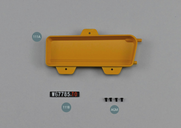
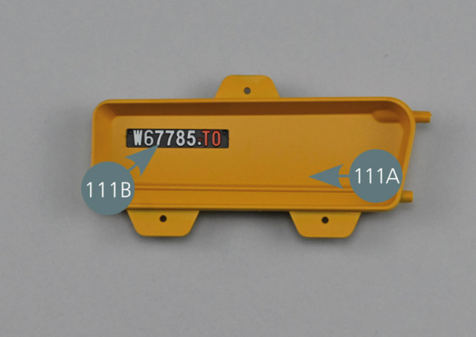
Placer la plaque d’immatriculation 111B en position retournée sur la surface de travail. Retirer le film de protection de la bande adhésive double-face. Positionner la plaque d’immatriculation 111B dans le coin intérieur supérieur gauche du panneau intérieur de portière droite #A 111A. Exercer une légère pression pour que l’adhésif double-face colle parfaitement.
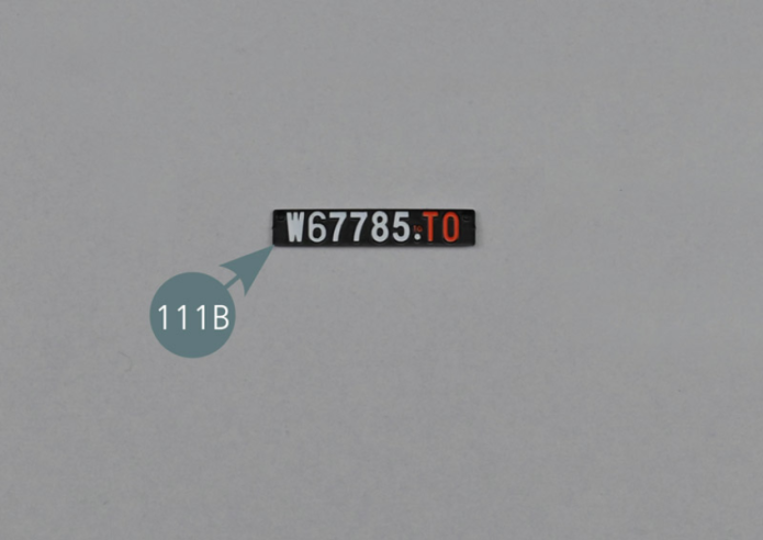
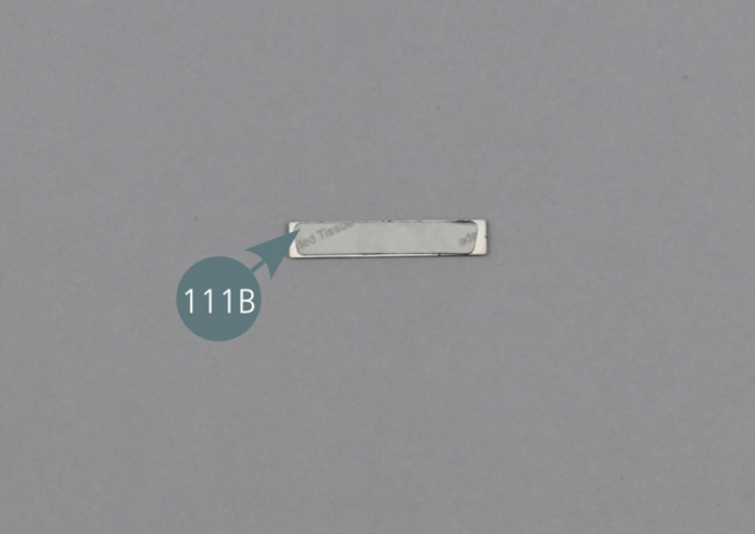
Place the number plate (111B) upside down on the work surface. Remove the protective film from the double-sided adhesive tape. Position the number plate (111B) in the upper left inside corner of the right door inner panel #A (111A). Apply slight pressure so that the double-sided adhesive sticks perfectly.
Etape 2


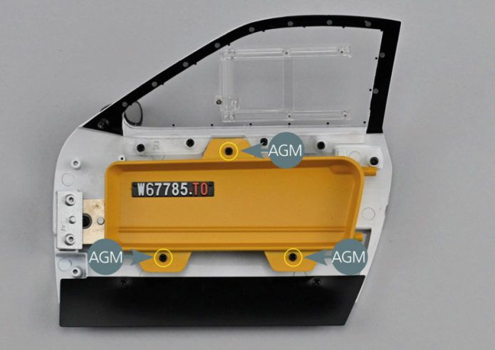
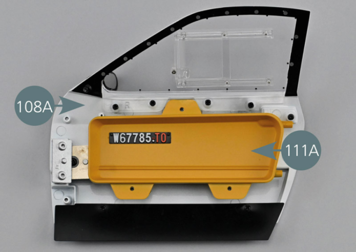
Positionner le panneau #A 111A sur l’intérieur de la portière gauche 108A comme indiqué, puis le fixer avec trois vis AGM.

Vue générale
Position panel #A (111A) on the inside of the right door (108A) as shown, then secure it with three AGM screws.
Kit 112 - Habillage intérieur de portière droite #B
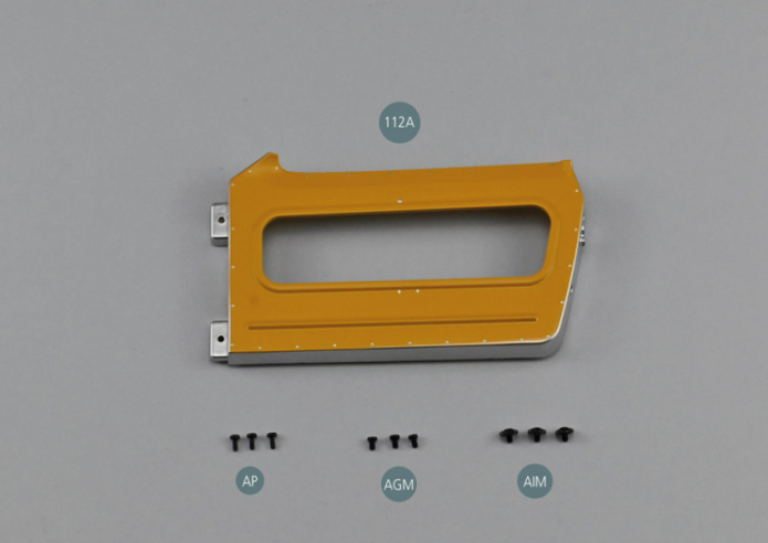
Parts of kit

Etape 1
- Screw AGM M 2.0 x 3 mm (x 3)
- Flat head screw AIM M 2.0 x 3 x 6 mm (x 3)
Positionner le panneau #B 112A sur l’intérieur de la portière droite 108A comme indiqué, puis le fixer avec deux vis AGM dans les deux trous indiqués par un cercle rouge.
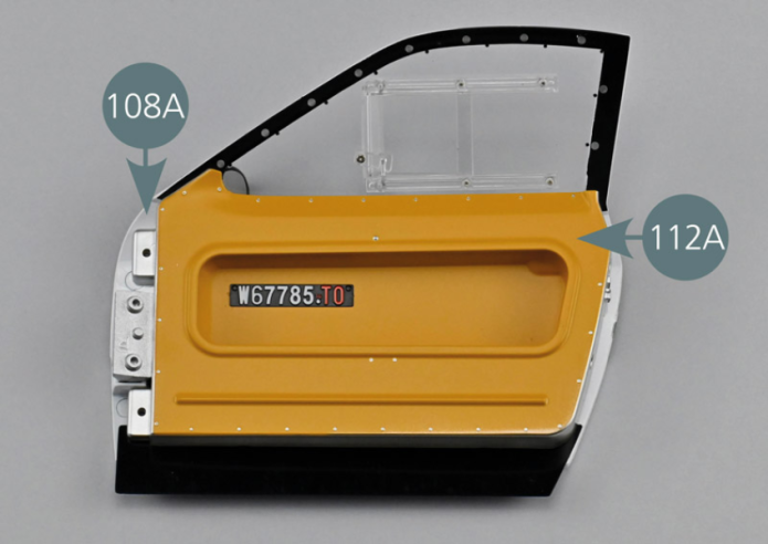
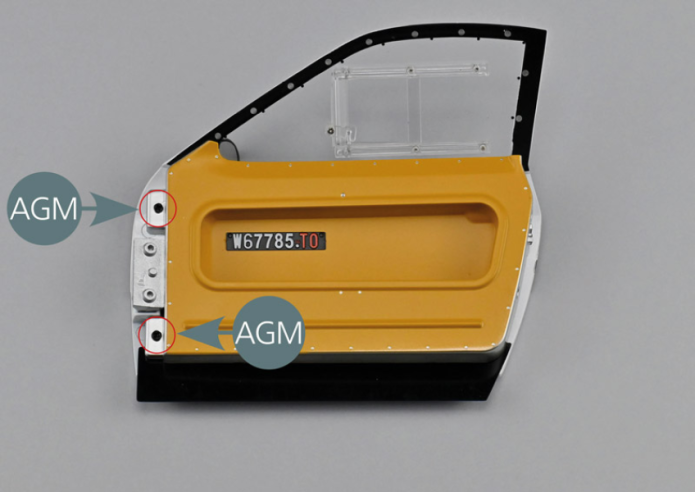
Position panel #B (112A) on the inside of the right door (108A) as shown, then secure it with two AGM screws into the two openings indicated by a red circle.

Fixer ensuite le panneau #B 112A sur le côté fermeture de la portière 108A avec deux vis AP (cercles jaunes).
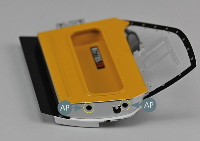
Etape 2
Then fix panel #B (112A) on the closing side of the door (108A) with two AP screws (yellow circles).

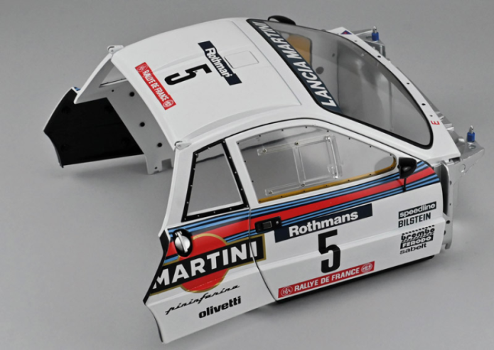
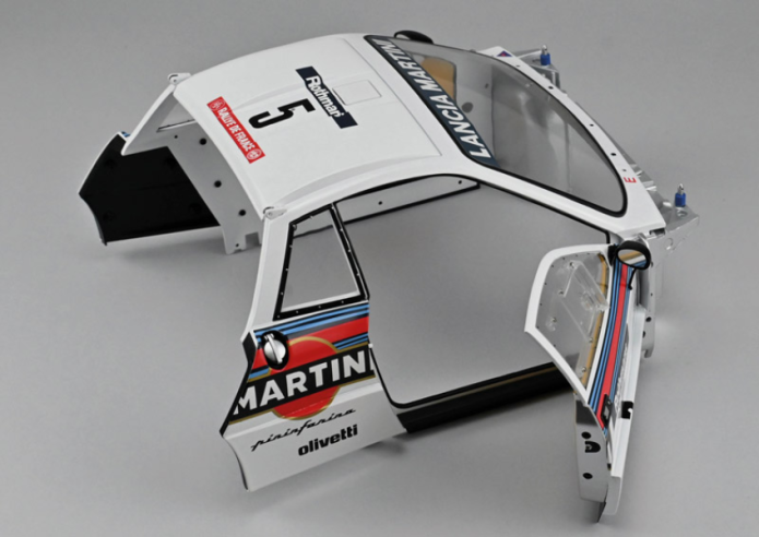
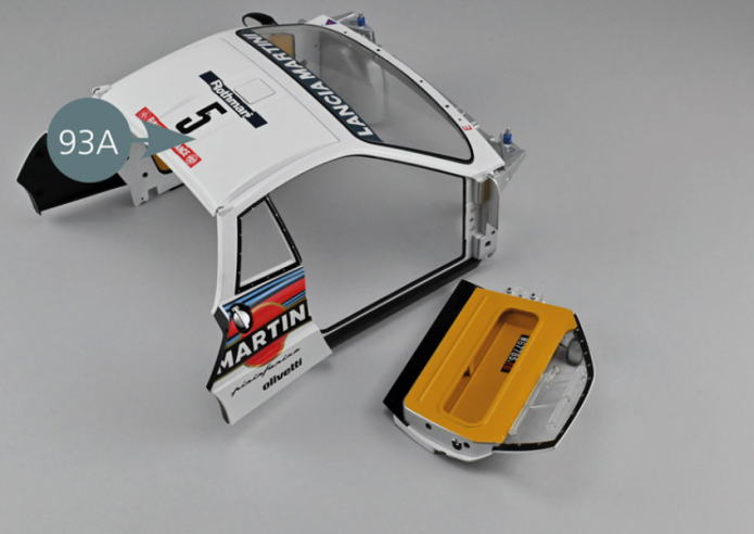
Reprendre la carrosserie 93A assemblée lors des étapes précédentes.
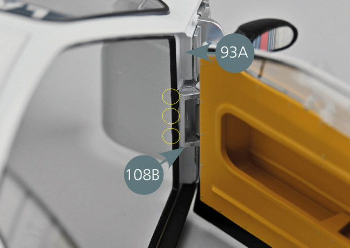
Ouvrir la charnière 108B et positionner les tétons en face des trois trous de la carrosserie 93A comme indiqué (cercles jaunes).
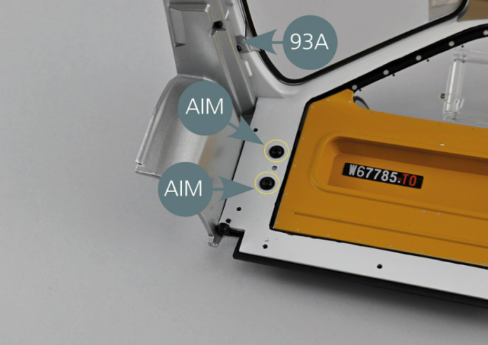
Fermer la portière et la fixer avec deux vis AIM. Commencer par serrer légèrement les vis, puis vérifier l’alignement et serrer ensuite les vis à fond.
Vérifier l’ouverture et la fermeture de la portière et agir sur les vis pour ajuster au mieux son positionnement si nécessaire.
Vue générale
Close the door and secure it with two AIM screws. Start by lightly tightening the screws, then check the alignment and tighten the screws fully. Check that the door opens and closes, and adjust the screws if necessary.