English
 français
 Deutsch
 español
 italiano
 português


Box 29
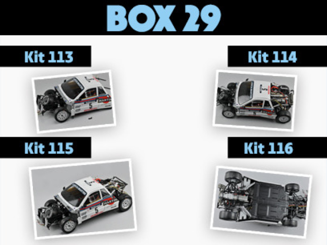
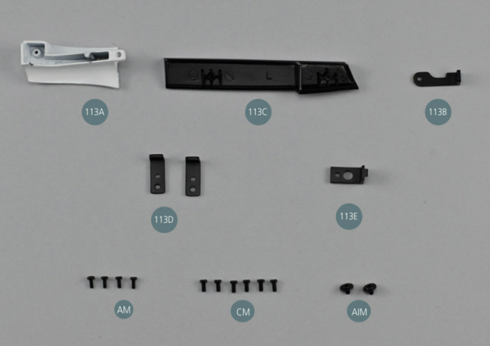
Kit 113 - Séparation capot-portière avant gauche
Parts of kit
- 113A Séparation capot-portière avant gauche
- 113B Support de séparation
- 113C Jupe arrière gauche
- 113D Attache inférieure (x 2)
- 113E Attache inférieure de plate-forme
- AM Vis M 1,7 x 4 mm (x 4)
- CM Vis M 2,0 x 4 mm (x 6)
- AIM Vis M à tête plate 2,0 x 3 mm (x 2)

Etape 1
- 113E Lower platform attachment
- Screw AM M 1.7 x 4 mm (x 4)
- Screw CM M 2.0 x 4 mm (x 6)
- Flat head screw AIM M 2.0 x 3 mm (x 2)
Rassembler le châssis et la partie centrale de la carrosserie montés dans les étapes précédentes.
Positionner la carrosserie 93A sur le châssis, en veillant à glisser la partie avant de la carrosserie entre la cloison d’habitacle avant 100A et la cloison pare-feu 9A.
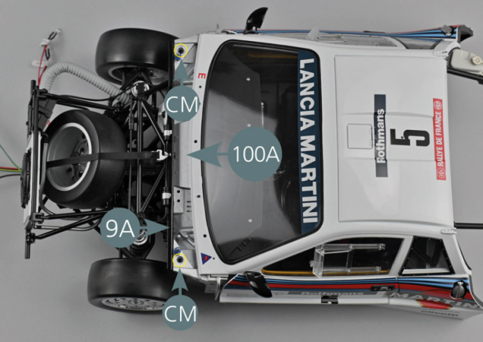
Fixer la carrosserie avec deux vis CM dans les logements situés à côté des goupilles de fixation du capot avant (cercles jaunes).
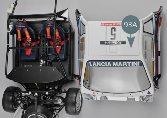
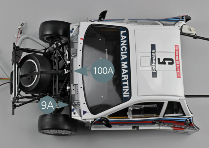
Gather the chassis and the central part of the bodywork assembled in the previous steps. Place the body (93A) on the chassis, making sure to slide the front part of the body between the front compartment bulkhead (100A) and the firewall (9A). Secure the bodywork with two CM screws in the slots located next to the front cover mounting pins (yellow circles).

Etape 2

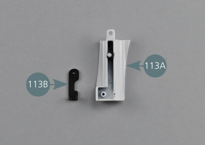
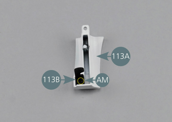
Positionner le support de séparation 113B sur la séparation capot-portière avant gauche 113A comme indiqué sur la photo, puis le fixer avec une vis AM.
Etape 3
Position the separation support (113B) on the left front bonnet-door partition (113A) as shown in the photo, then secure it with an AM screw.


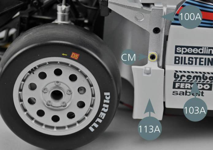
Positionner la séparation 113A devant la portière avant gauche 103A comme indiqué et la fixer sur la cloison d’habitacle avant 100A avec une vis CM.
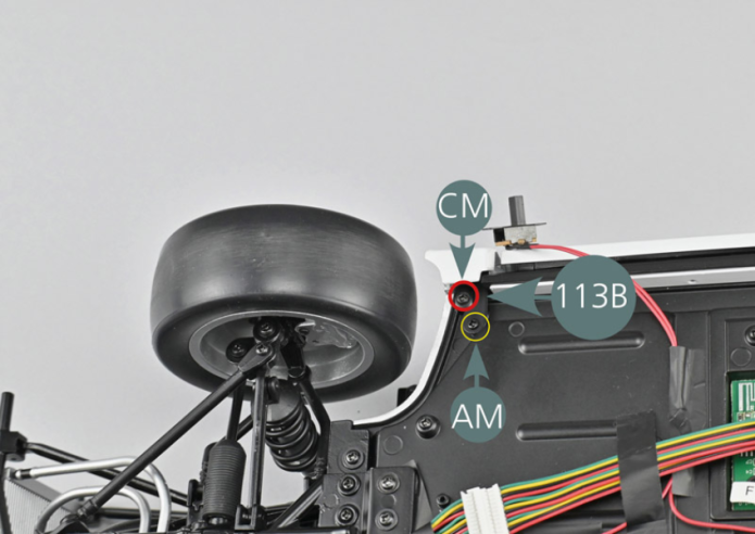
Retourner l’ensemble et fixer la carrosserie avec une vis CM (cercle rouge). Fixer ensuite le support de séparation 113B sur le plancher gauche du cockpit 67A avec une vis AM (cercle jaune).


Etape 4
Position the partition (113A) in front of the left front door (103A) as shown and secure it to the front compartment bulkhead (100A) with a CM screw. Turn the assembly over and secure the body with a CM screw (red circle). Then secure the partition support (113B) to the left floor panel (67A) with an AM screw (yellow circle).
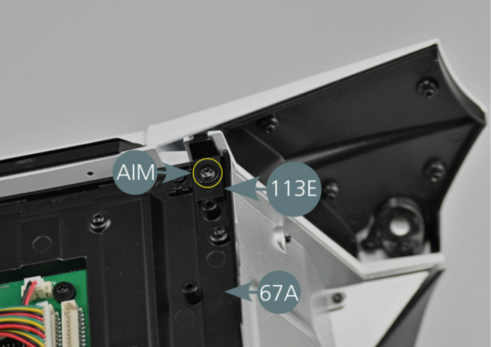
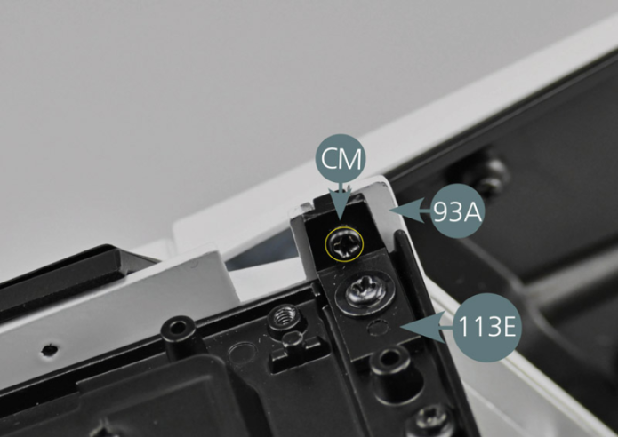
Positionner l’attache inférieure de plate-forme 113E sur le plancher gauche du cockpit 67A et la fixer avec une vis AIM.
Fixer ensuite l’attache inférieure 113E sur la partie centrale de la carrosserie 93A avec une vis CM.


Etape 5
Place the lower platform attachment (113E) on the left floor panel (67A) and secure it with an AIM screw. Then secure the lower attachment (113E) to the central part of the body (93A) with a CM screw.
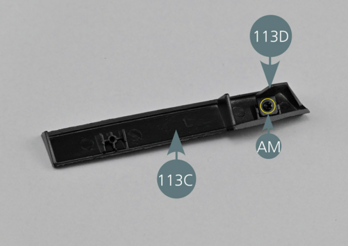
Positionner une attache inférieure 113D sur la jupe arrière gauche 113C et la fixer avec une vis AM.
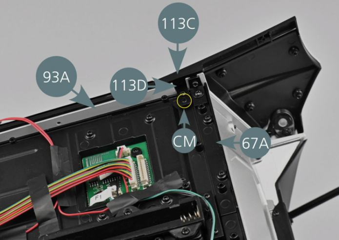
Positionner ensuite la jupe 113C sur la partie arrière de la carrosserie 93A et fixer l’attache inférieure 113D
au plancher gauche du cockpit 67A avec une vis CM comme indiqué (cercle jaune).
Mettre de côté la seconde attache 113D qui sera utilisée lors d’une étape ultérieure.
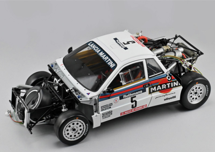
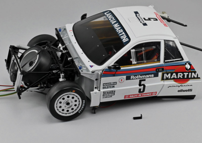
Vue générale
Position a lower attachment (113D) on the left rear skirt (113C) and secure with an AM screw. Then position the skirt (113C) on the rear part of the body (93A) and secure the lower attachment (113D) to the left floor panel (67A) with a CM screw as shown (yellow circle). Put the second attachment (113D) aside - this will be used at a later stage.

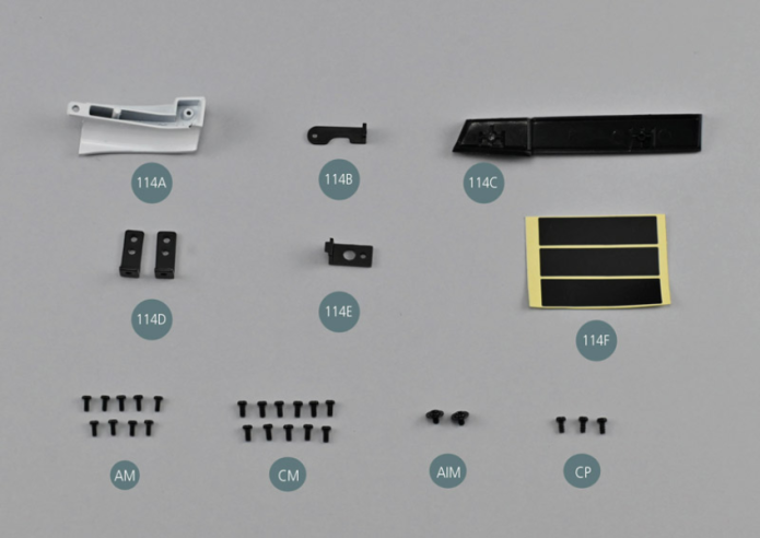
Kit 114 - Séparation capot-portière avant droite
Parts of kit

Etape 1
- 114F Adhesive tape (x 3)
- Screw AM M 1.7 x 4 mm (x 9)
- Screw CM M 2.0 x 4 mm (x 11)
- Flat head screw AIM M 2.0 x 3 mm (x 2)
- Screw CP P 2.0 x 4 mm (x 3)
Positionner le support de séparation 114B sur la séparation capot-portière avant droite 114A comme indiqué sur la photo, puis le fixer avec une vis AM (cercle jaune).
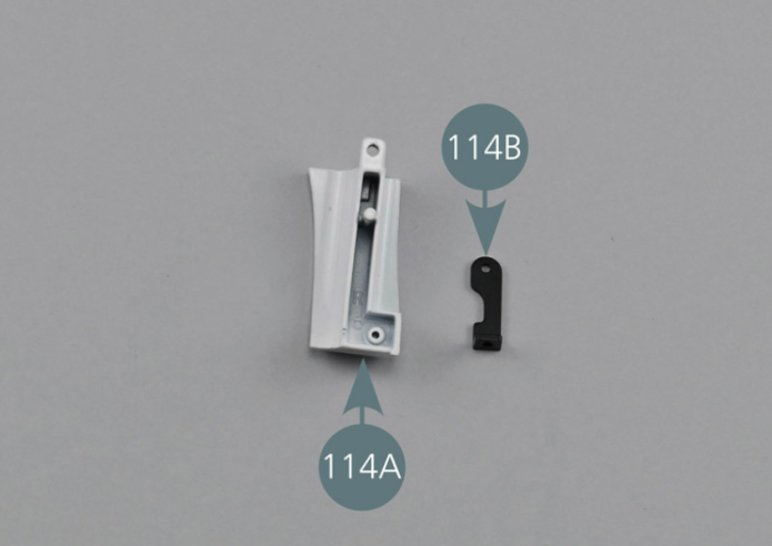
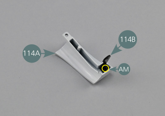
Etape 2
Position the partition support (114B) on the right front bonnet-door partition (114A) as shown in the photo, then secure it with an AM screw.


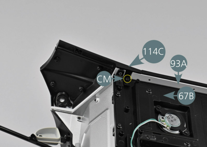
Positionner la séparation 114A devant la portière avant droite 108A comme indiqué et la fixer sur la cloison d’habitacle avant 100A avec une vis CM (cercle jaune).
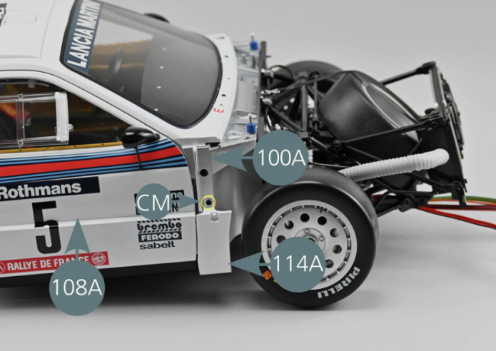

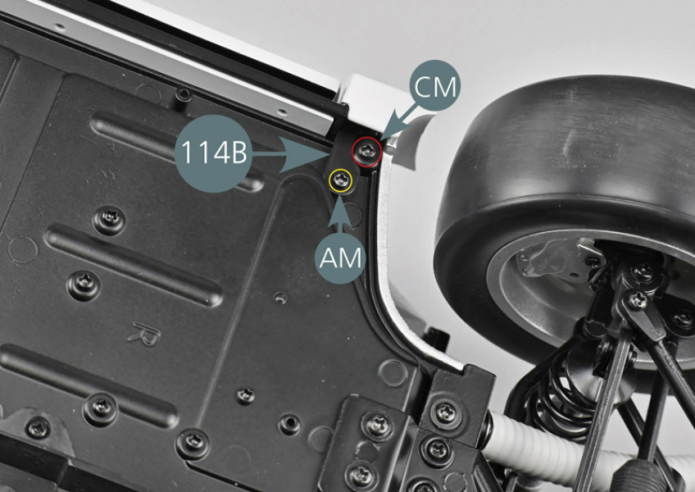
Retourner l’ensemble et fixer la carrosserie avec une vis CM (cercle rouge). Fixer ensuite le support de séparation 114B sur le plancher droit du cockpit 67B avec une vis AM (cercle jaune).
Etape 3
Turn the assembly over and secure the body with a CM screw (red circle). Then secure the partition support (114B) to the right floor panel (67B) with an AM screw (yellow circle).

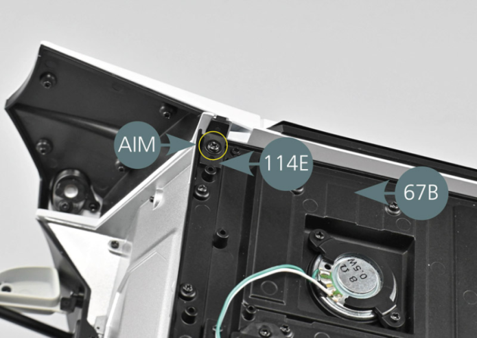
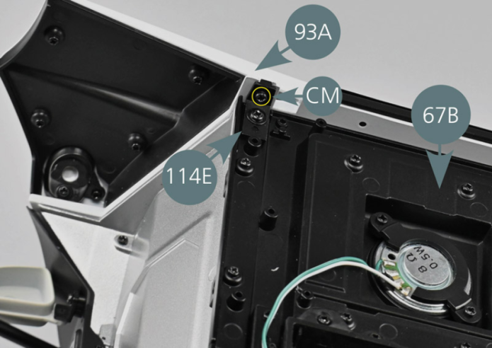
Positionner l’attache inférieure de plate-forme 114E sur le plancher droit du cockpit 67B et la fixer avec une vis AIM. Fixer ensuite l’attache inférieure 114E sur la partie centrale de la carrosserie 93A avec une vis CM.

Etape 4
Place the lower platform attachment (114E) on the right floor panel (67B) and secure it with an AIM screw. Then secure the lower attachment (114E) to the central part of the body (93A) with a CM screw.

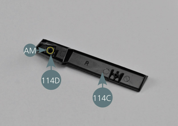
Positionner une attache inférieure 114D sur la jupe arrière droite 114C et la fixer avec une vis AM.
Positionner ensuite la jupe 114C sur la partie arrière de la carrosserie 93A et fixer l’attache inférieure 114D au plancher gauche du cockpit 67B avec une vis CM comme indiqué (cercle jaune).

Etape 5
Position a lower attachment (114D) on the right rear skirt (114C) and secure it with an AM screw. Then position the skirt (114C) on the rear part of the body (93A) and secure the lower attachment (114D) to the left floor panel (67B) with a CM screw as shown (yellow circle).

Connecter le groupement de câbles des feux arrière 19A sur le circuit imprimé 18C.
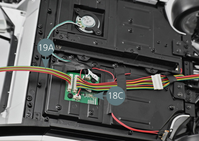

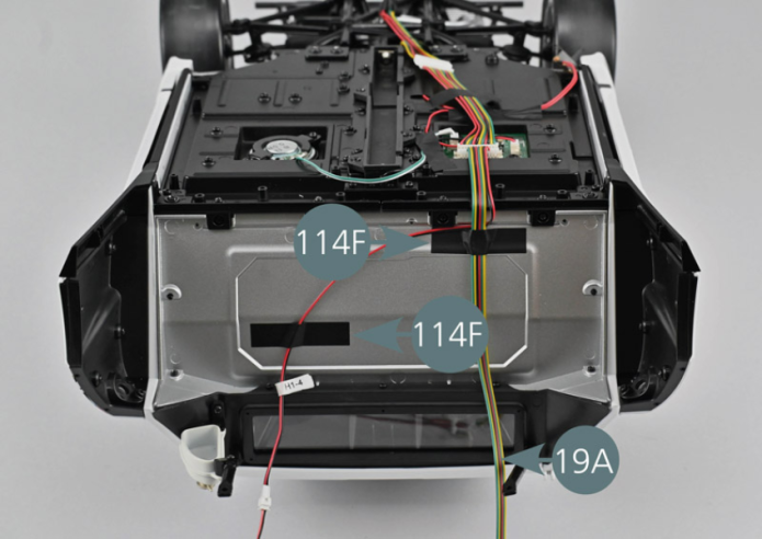
Séparer délicatement le câble de clignotant droit (H1-4) du reste des câbles et les fixer avec deux rubans adhésifs 114F comme indiqué sur la photo.
Etape 6
Carefully separate the wire of the right blinking light (H1-4) from the rest of the wires and secure them with two adhesive tapes (114F) as per picture.

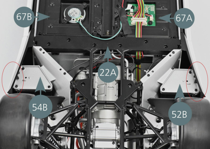
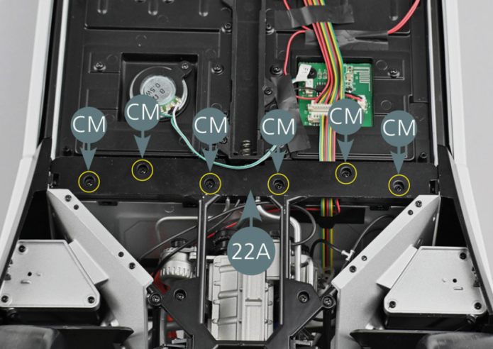
Prendre l’ensemble du montage du moteur, le retourner et placer le cadre inférieur du châssis arrière 22A sur le plancher gauche 67A et droit 67B.
Vérifier que les réservoirs de carburant 52B et 54B sont positionnés légèrement plus bas que les deux jupes arrière (cercles rouges).
Fixer le cadre inférieur du châssis arrière 22A sur le plancher avec six vis CM.

Fixer le cadre inférieur du châssis arrière 22A sur le plancher avec six vis CM.

Etape 7
Secure the lower rear frame (22A) to the floor panels using six CM screws.
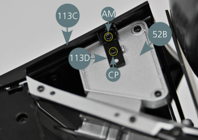
Prendre l’attache inférieure 113D mise de côté précédemment, puis la fixer sur le réservoir gauche 52B avec une vis CP et sur la jupe arrière gauche 113 C avec une vis AM.
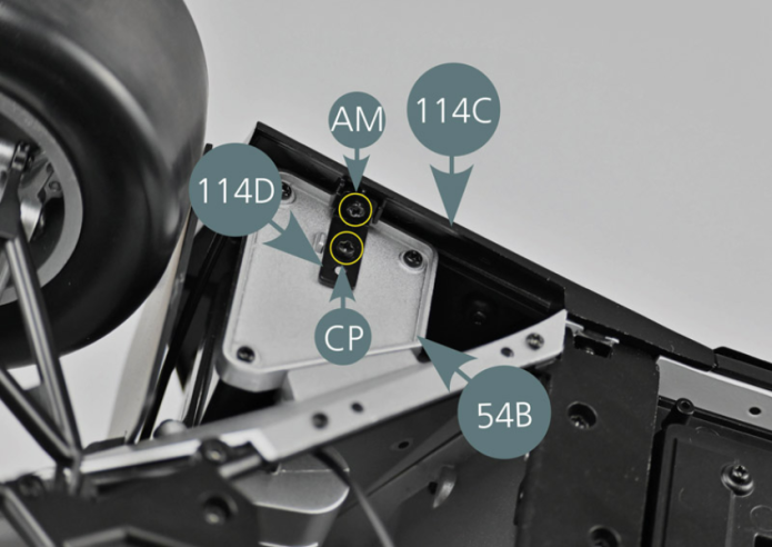
Prendre ensuite l’attache inférieure 114D et la fixer sur le réservoir droit 54B avec une vis CP et sur la jupe arrière droite 114 C avec une vis AM.

Etape 8
Take the lower attachment (113D) that you have set aside in an earlier stage, then fix it to the left fuel tank (52B) with a CP screw and to the left rear skirt (113C) with an AM screw. Then take the lower attachment (114D) and secure it to the right fuel tank (54B) with a CP screw and to the right rear skirt (114C) with an AM screw.

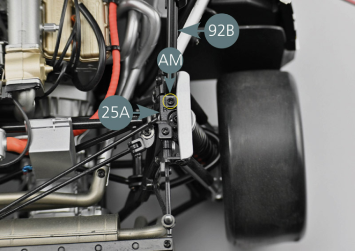
Retournez l’ensemble et fixez les barres de renfort supérieur arrière gauche 92A et droite 92B sur le cadre du moteur (bras de liaison trapézoïdal arrière 24A et 25A) avec deux vis AM comme indiqué (cercles jaunes).
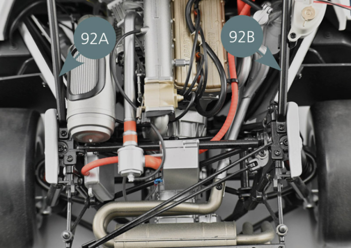
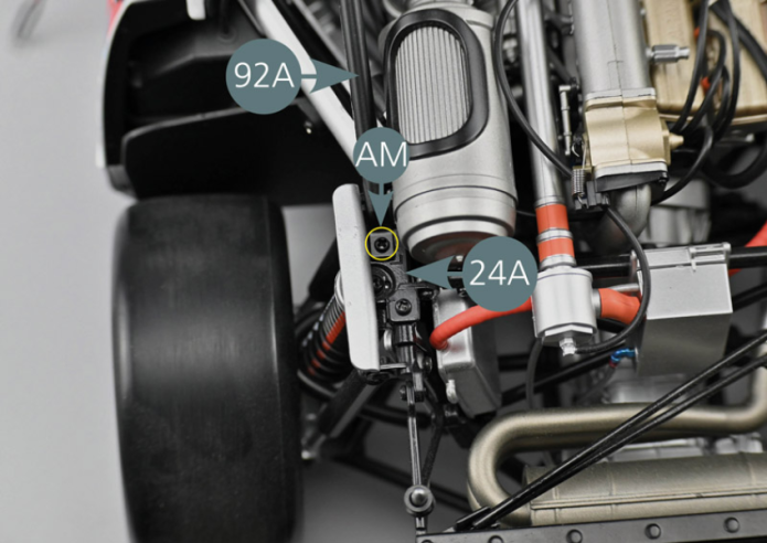
Turn the assembly over and attach the left and right rear upper reinforcement bars (92A&92B) to the engine frame (rear trapezoidal link arm 24A&25A) with two AM screws as shown (yellow circles).

Etape 9


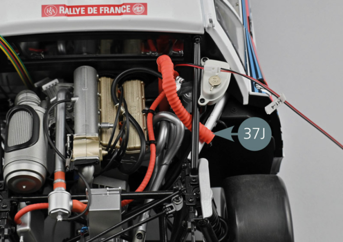
Faire passer la conduite d’air 37J sous la barre de renfort supérieur arrière droite 92 du cadre comme indiqué.
Vue générale
Route the air duct (37J) under the right rear upper reinforcement bar (92B) of the frame as shown.

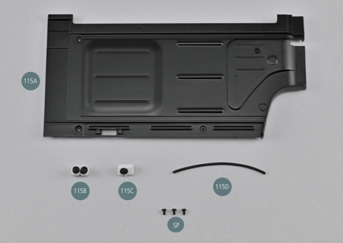
Kit 115 - Panneau de châssis inférieur gauche
Parts of kit
Etape 1
- 115D Hose
- Screw SP P 1.7 x 3 mm (x 3)

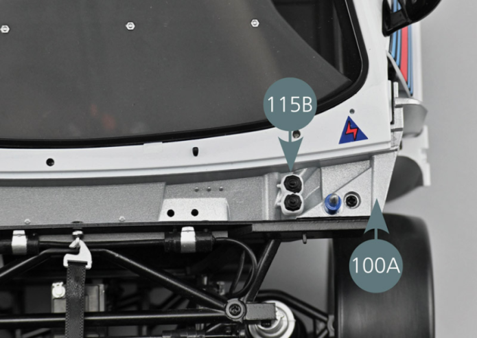
Positionner le vase d’expansion double 115B sur les ergots prévus sur la cloison d’habitacle avant 100A.

Etape 2
Place the double expansion tank (115B) on the lugs provided on the front passenger compartment bulkhead (100A).

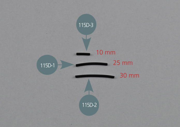
Couper trois sections dans le tuyau 115D, de 30 mm de long (115-D2), 25 mm de long (115-D1) et 10 mm de long (115-D3).
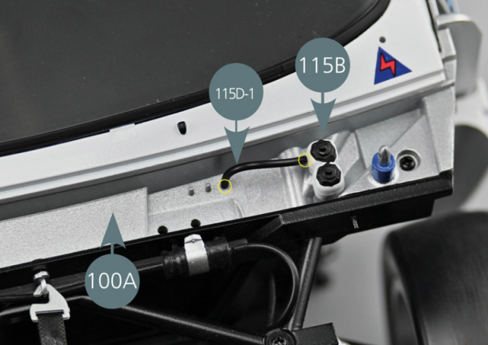
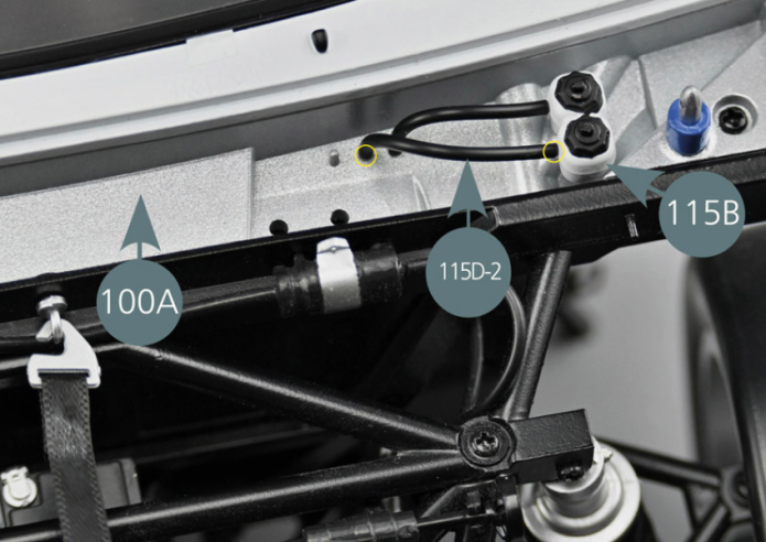
Insérer les extrémités du tube de 25 mm (115D-1) sur l’ergot du vase d’expansion double 115B le plus près du pare-brise et sur le premier des trois ergots situés sur la cloison d’habitacle avant 100A, comme indiqué sur la photo (cercles jaunes). Insérer ensuite les extrémités du tube de 30 mm (115D-2) sur l’ergot du second vase d’expansion double 115B et sur le deuxième des trois ergots situés sur la cloison d’habitacle avant 100A, comme indiqué sur la la photo de droite (cercles jaunes).


Etape 3
Insert the ends of the 25 mm hose (115D-1) on the lug of the dual expansion tank (115B) closest to the windshield and onto the first of the three lugs located on the bulkhead front compartment (100A), as shown in the photo (yellow circles). Then insert the ends of the 30 mm hose (115D-2) on the lug of the second dual expansion tank (115B) and onto the second of the three lugs located on the bulkhead front compartment (100A), as shown in the photo on the right (yellow circles).
Insérer l’une des extrémités du tube de 10 mm (115D-3) sur l’ergot du vase d’expansion simple 115C.
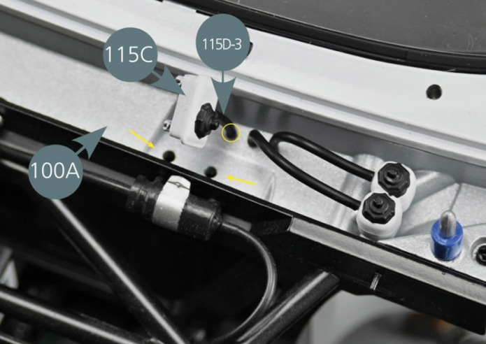
Insérer l’autre extrémité du tube de 10 mm (115D-3) sur le troisième des trois ergots situés sur la cloison d’habitacle avant 100A, comme indiqué sur la photo (cercle jaune).
Positionner ensuite les ergots situés sous le vase d’expansion simple 115C dans les deux trous indiqués par les flèches jaunes.
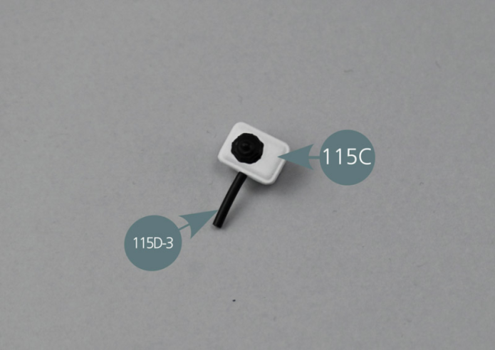

Insert one end of the 10 mm hose (115D-3) on the lug on the single expansion tank (115C). Insert the other end of the 10 mm hose (115D-3) onto the third of the three lugs located on the bulkhead front compartment (100A), as shown in the photo (yellow circle). Then position the lugs located under the single expansion tank (115C) into the two openings indicated by the yellow arrows.
Etape 4

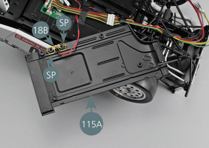
Fixer l’interrupteur 18B sur le panneau de châssis inférieur gauche 115A avec deux vis SP (cercles jaunes).
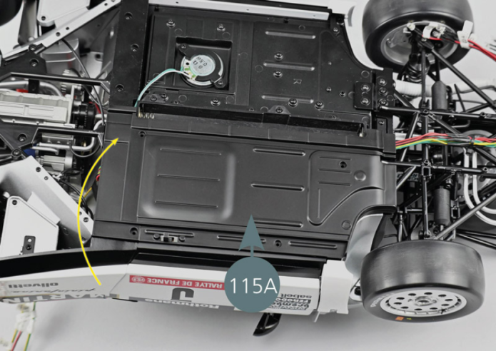
Veiller à ce que les connexions soient orientées vers l’intérieur du fond et que les deux contacts soudés soient vers la droite. Retourner le panneau de châssis inférieur gauche 115A et le placer temporairement sur la base du châssis.
Vue générale
Attach the switch of the battery compartment (18B) to the left lower chassis panel (115A) with two SP screws (yellow circles). Make sure that the connections are oriented towards the inside of the bottom and that the two soldered contacts are towards the right. Turn the left lower chassis panel (115A) over and place it temporarily on the chassis base.


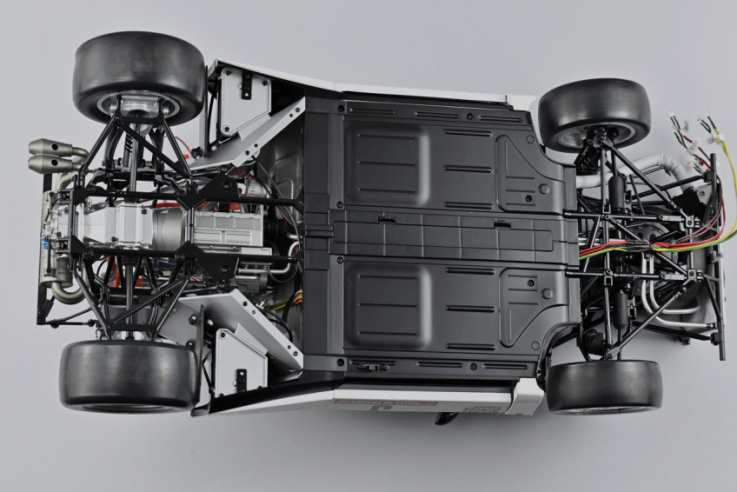
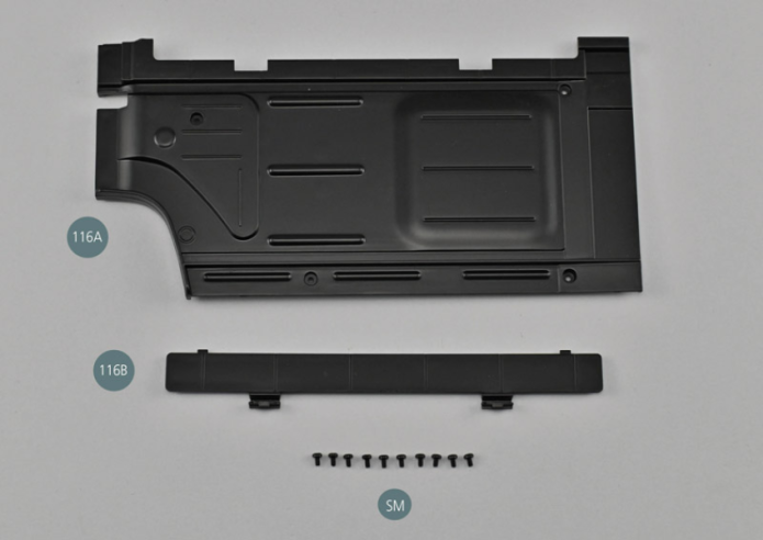
Kit 116 - Panneau de châssis inférieur droit
Parts of kit

Etape 1
- Screw SM M 14.7 x 3 mm (x 10)
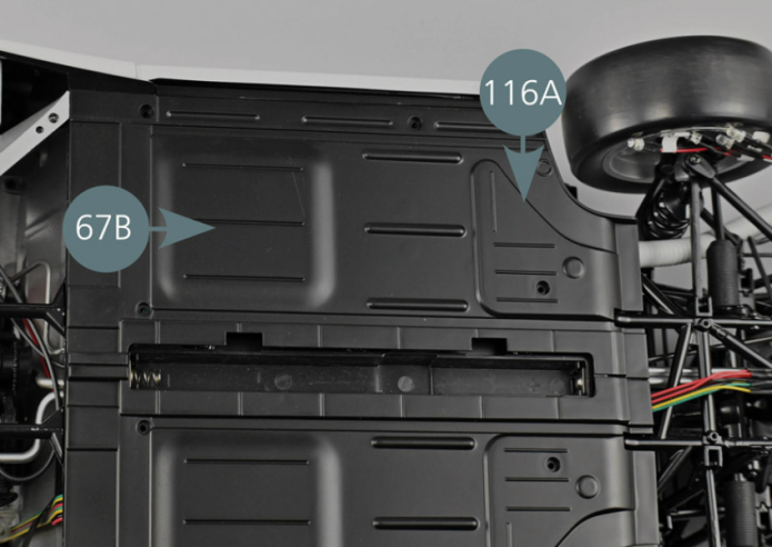
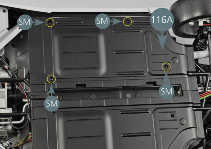
Positionner le panneau de châssis inférieur droit 116A sur la partie inférieure du plancher droit du cockpit 67B, puis le fixer avec quatre vis SM comme indiqué (cercles jaunes).


Etape 2
Place the right lower chassis panel (116A) on the lower part of the right floor panel (67B), then secure it with four SM screws as shown (yellow circles).
Fixer ensuite le panneau de châssis inférieur gauche 115A avec quatre vis SM.
Insérer trois piles type AAA dans le compartiment à piles en respectant la polarité, le ressort étant du côté du pôle négatif (cercle jaune).
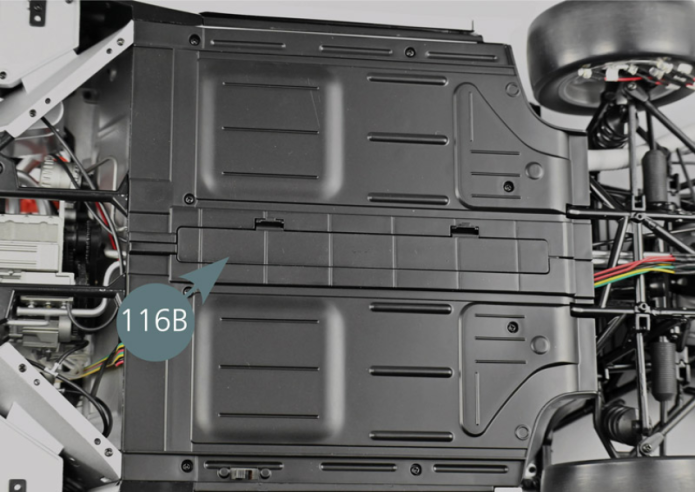
Positionnez le couvercle du compartiment à piles 116B.
Il est maintenant possible de tester le système électrique à l’aide de la télécommande fournie précédemment.
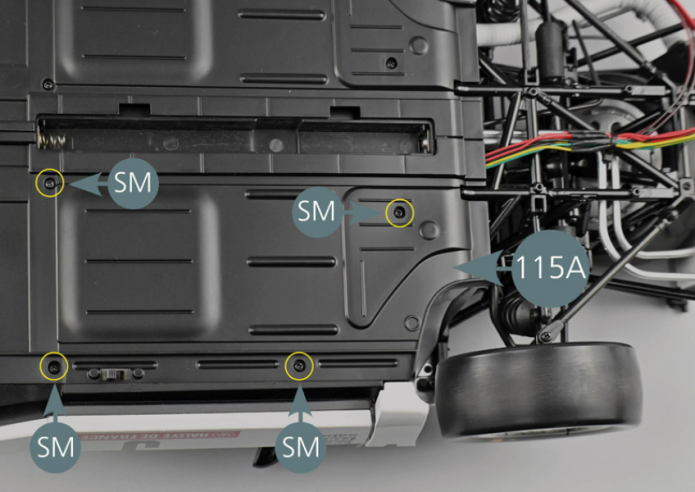
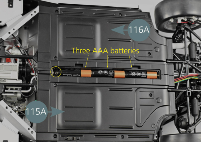
Next, secure the left lower chassis panel (115A) with four SM screws. Insert three AAA batteries into the battery compartment, respecting the polarity, with the spring on the negative side (yellow circle). Place the battery compartment cover (116B). It is now possible to test the electrical system using the remote control previously provided.
Vue générale