English
 français
 Deutsch
 español
 italiano
 português


Box 30
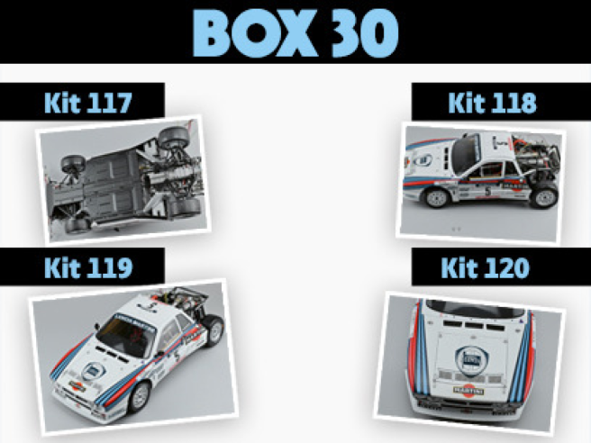
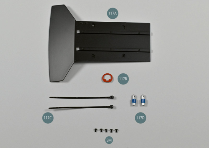
Kit 117 - Plaque de protection frontale du châssis
Parts of kit
- 117A Plaque de protection frontale
- 117B Anneau de remorquage
- 117C Attache en nylon (x 2)
- 117D Support de goupille de capot avant (x 2)
- SM Vis M 1,7 x 3 mm (x 5)

Etape 1
- 117D Front bonnet support pin (x 2)
- Screw SM M 1.7 x 3 mm (x 5)
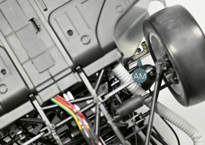
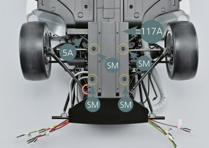
Placer la Lancia 037 à l’envers et retirer les vis AM situées à gauche et à droite (cercle jaune), puis les mettre de côté.
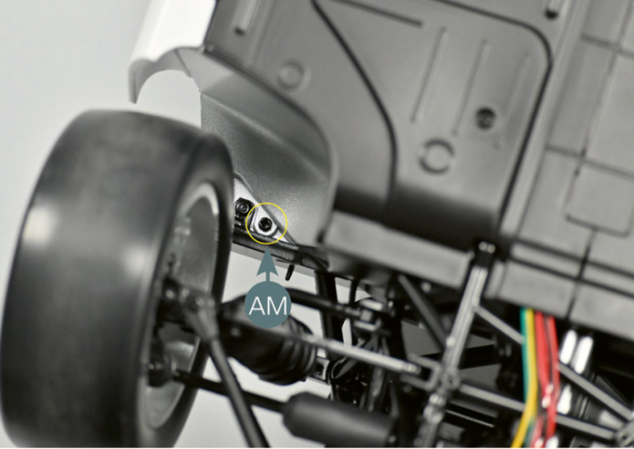
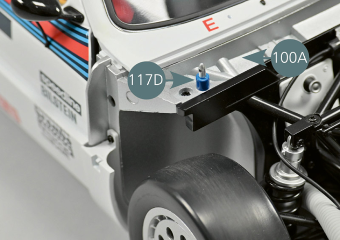
Retourner à nouveau le véhicule et remplacer les deux supports de goupille de capot avant 100B situés de part et d’autre de la cloison d’habitacle avant 100A par les supports de goupille de capot avant 117D.
Réinsérer ensuite dans leurs logements les vis AM retirées précédemment.
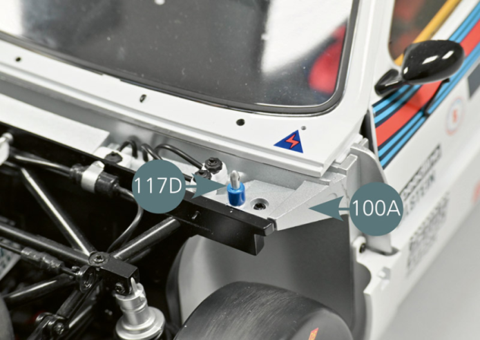
Turn the vehicle over again and replace the two front bonnet pin brackets 100B located on either side of the front passenger compartment bulkhead 100A with the front bonnet pin brackets 117D.Then reinsert the AM screws removed earlier into their housings.
Etape 2


Etape 3
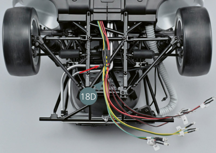
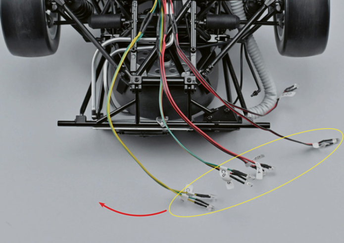
Retourner le véhicule et, à l’aide de ciseaux, couper la partie qui dépasse de l’attache qui retient les câbles 18D au châssis, comme indiqué par la flèche rouge.
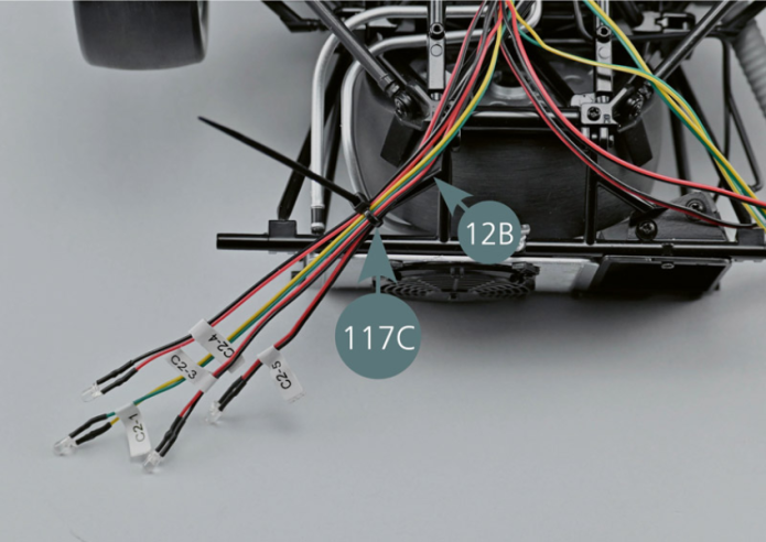
Séparer délicatement les câbles 18D C2-1, C2-3, C2-4, C2-5 et C2-6 (cercle jaune), puis déplacer la moitié d’entre eux vers le côté gauche comme indiqué par la flèche rouge. Les fixer avec une nouvelle attache 117C sur la barre inférieure 12B (voir la photo).
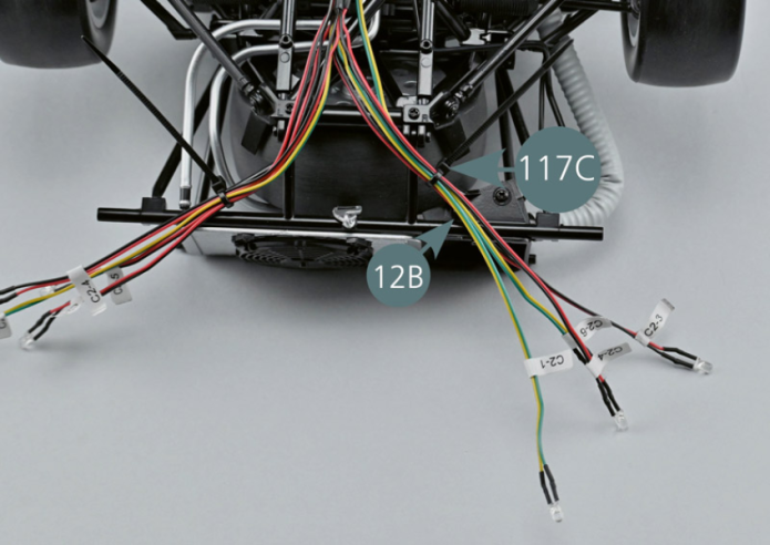
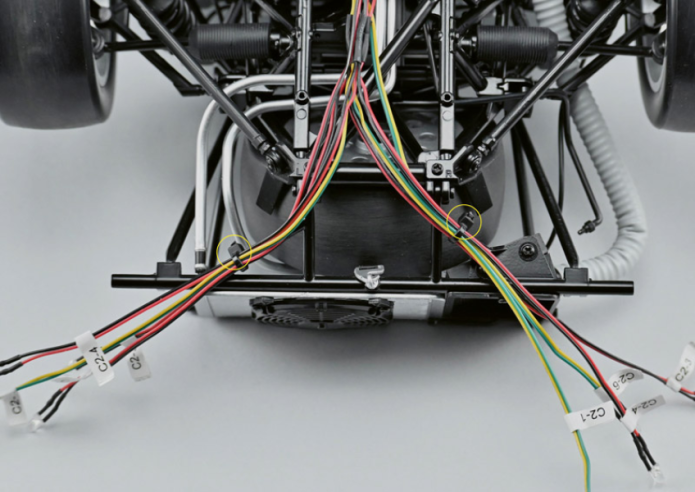
Déplacer ensuite l’autre moitié des câbles 18D C2-1, C2-3, C2-4, C2-6 vers le côté droit et les fixer avec une nouvelle attache 117C sur la barre inférieure 12B. Couper avec des ciseaux la partie qui dépasse des attaches de câble, comme indiqué par les cercles jaunes.

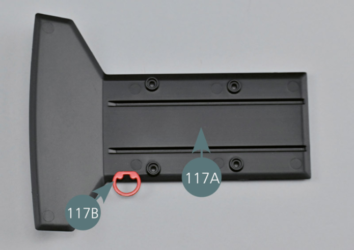
Fixer en l’enfonçant l’anneau de remorquage 117B sur la face inférieure de la plaque de protection frontale 117A comme indiqué. Placer la plaque de protection frontale 117A sur le cadre inférieur avant 5A et la fixer avec quatre vis SM.
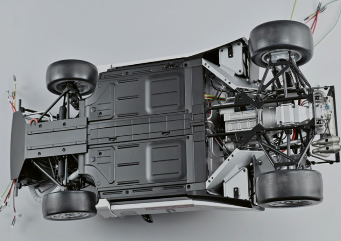
Vue générale
Press the towing eye (117B) onto the lower part of the front protection plate (117A) as shown. Place the front protection plate (117A) on the front lower frame (5A) and secure with four SM screws.

Kit 118 - Supports du capot avant
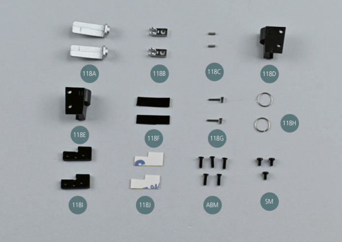
Parts of kit
Etape 1
- 118G Retaining clip pin (x 2)
- 118H Retaining ring (x 2)
- 118I Hinge spacer (x 2)
- 118J Double-sided adhesive tape (x 2)
- Screw ABM M 1.7 x 6 mm (x 5)
- Screw SM M 1.7 x 3 mm (x 3)
À l’aide d’une pince brucelle, insérer les axes 118C, d’un seul côté seulement, dans les deux attaches du capot avant 118B.
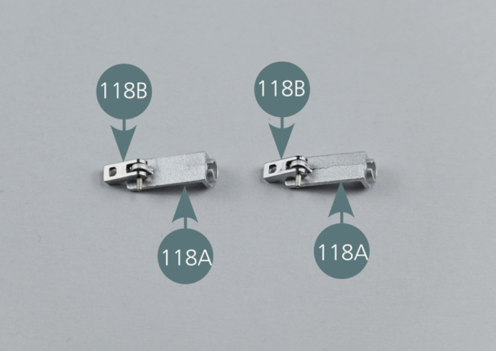
Positionner les deux attaches du capot avant 118B sur les deux supports 118A.
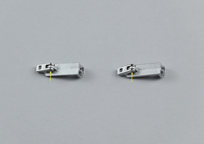
Insérer les axes 118C jusqu’au bout, comme indiqué par les flèches jaunes, afin que les blocs 118B puissent se déplacer vers le haut et le bas.
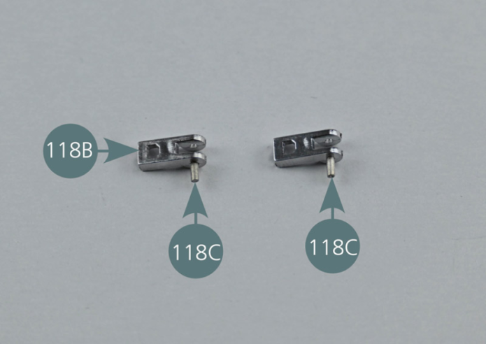
Use a pair of tweezers to insert the axles (118C), on one side only, into the two front bonnet fasteners (118B).
Position the two front bonnet fasteners (118B) on the two supports (118A). Insert the pins (118C) all the way through, as indicated by the yellow arrows, so that sections (118B) can move up and down.
Etape 2


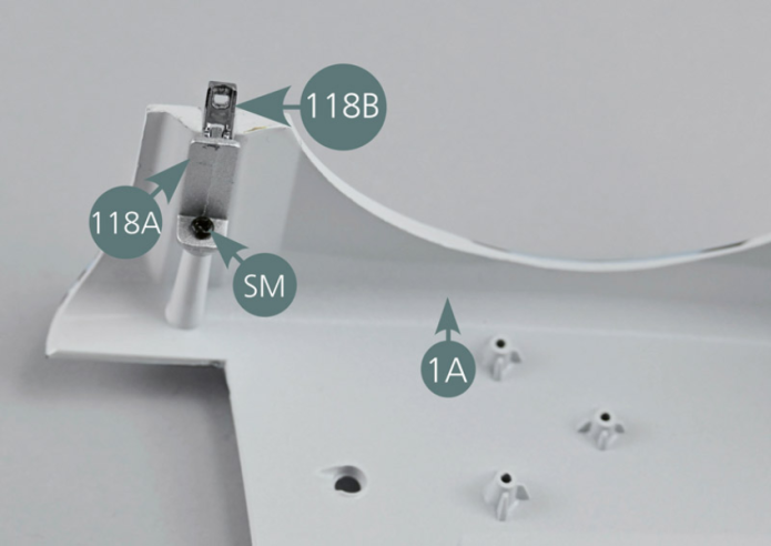
Placer le capot avant 1A à l’envers sur le plan de travail.
Positionner les ensembles supports 118A et attaches 118B (tournés vers l’extérieur) de chaque côté du capot avant 1A comme indiqué par les cercles pointillés jaunes, puis les fixer avec une vis SM.
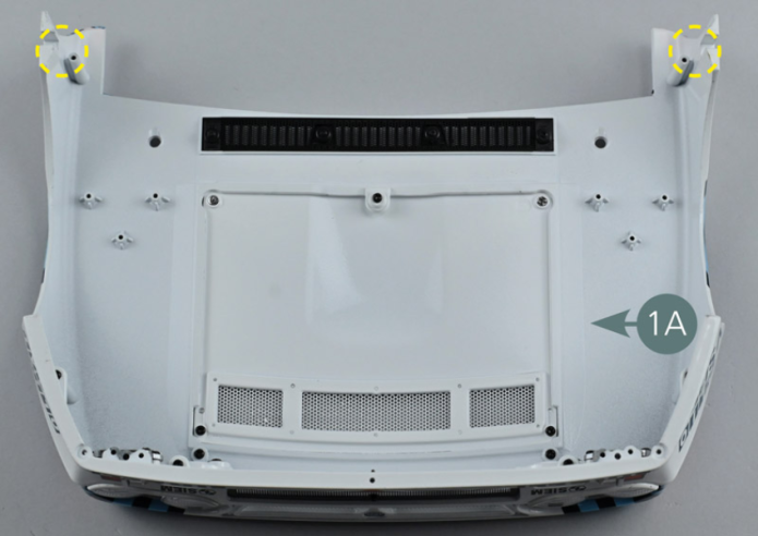
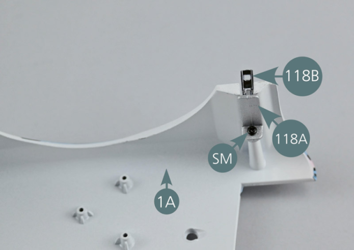
Place the front bonnet (1A) face down on the worktop.
Position the support (118A) and fastener (118B) assemblies (facing outwards) on either side of the bonnet (1A) as indicated by the yellow dotted circles, then secure them with an SM screw.
Etape 3


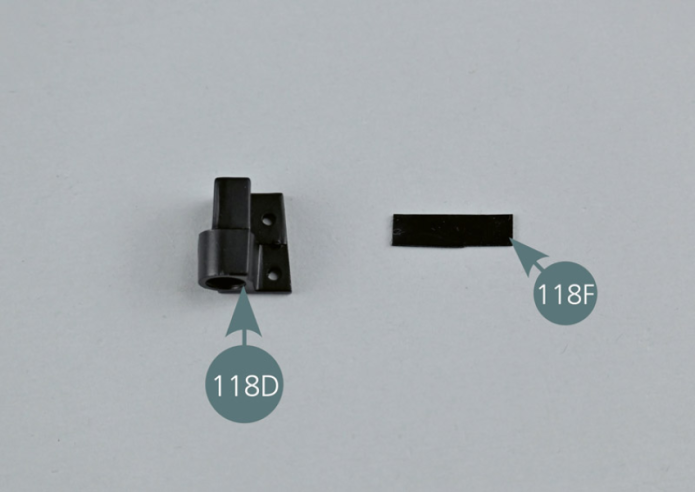
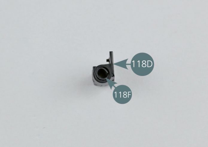
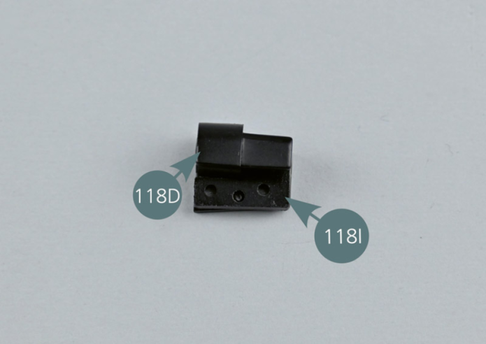
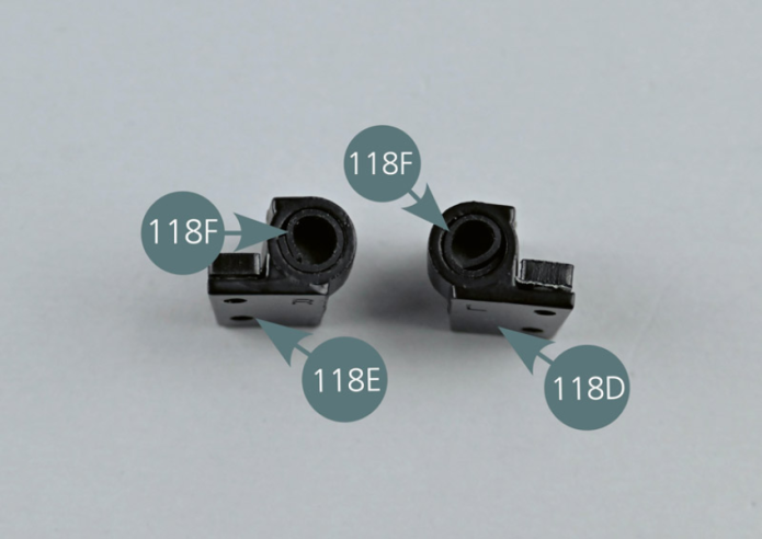
Enrouler une bande de caoutchouc 118F et l’insérer dans le logement circulaire de la charnière gauche du capot avant 118D.

Etape 4
Wind a rubber strip (118F) and insert it into the circular recess in the left hinge of the front cover (118D).

Enlever le film de protection d’un adhésif double-face 118J.
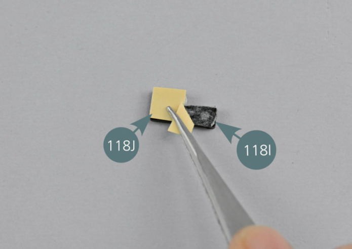
Positionner l’adhésif 118J sur l’une des entretoises de charnière 118I.
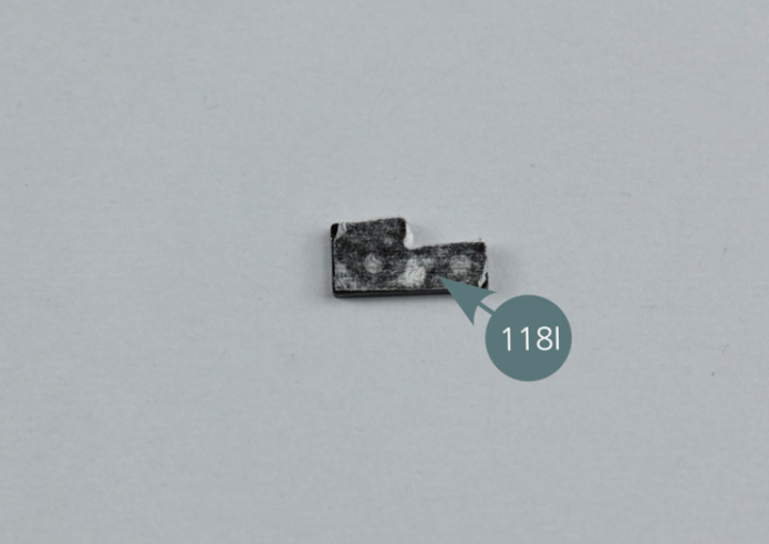
Enlever le second film de protection de l’adhésif 118J et fixer l’entretoise 118I sur la charnière gauche 118D comme indiqué.
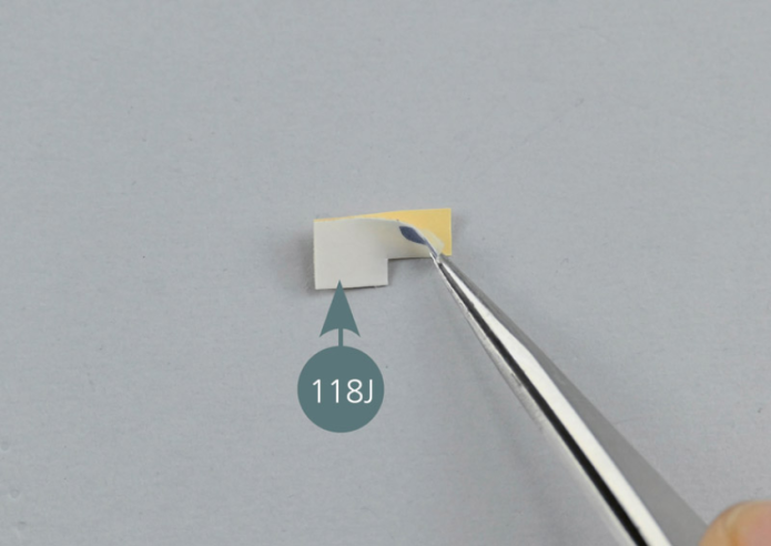
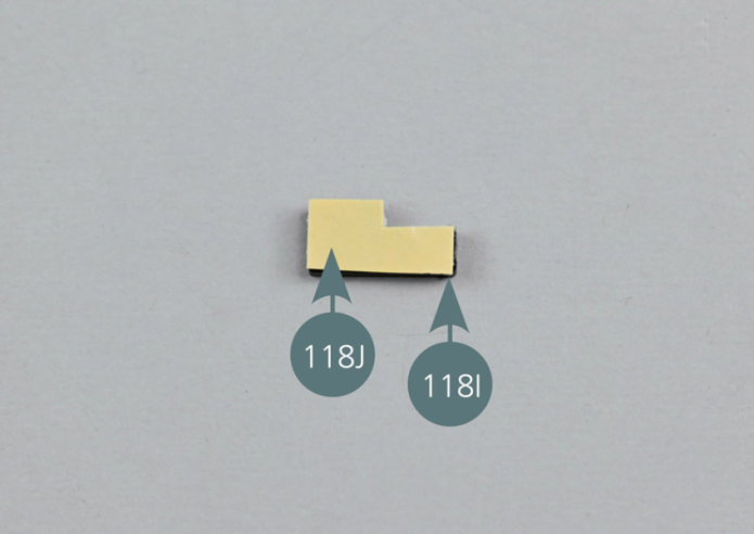
Remove the protective film from a double-sided adhesive tape (118J). Apply the adhesive (118J) onto one of the hinge spacers (118I).
Remove the second protective film from the adhesive tape (118J) and attach the spacer (118I) to the left hinge (118D) as shown.

Etape 5

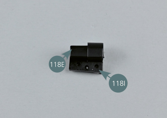
Répéter l’opération pour la charnière droite 118E, l’entretoise 118I, la bande de caoutchouc 118F et l’adhésif double-face 118J.
Etape 6
Repeat the process for the right hinge (118E), the spacer (118I), the rubber strip (118F) and the double-sided adhesive tape (118J).


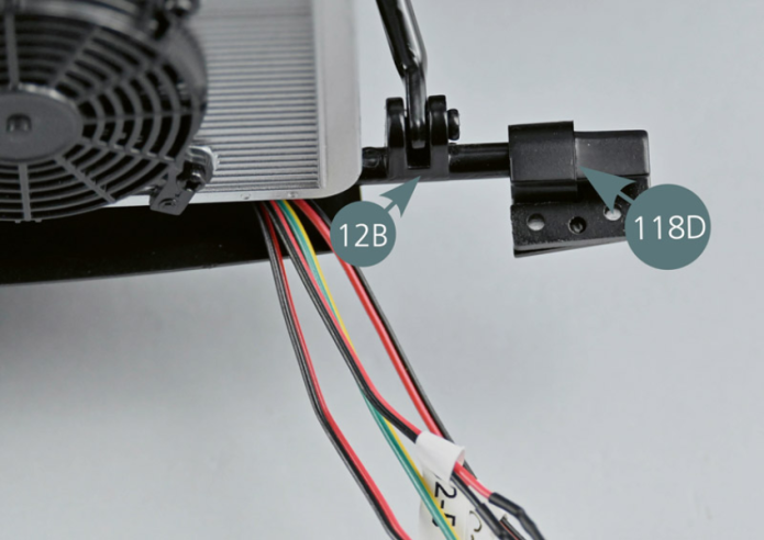
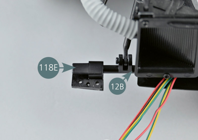
Positionner la charnière gauche 118D et la charnière droite 118E aux extrémités opposées de la barre inférieure 12B.


Etape 7
Position the left hinge (118D) and the right hinge (118E) at opposite ends of the lower bar (12B).
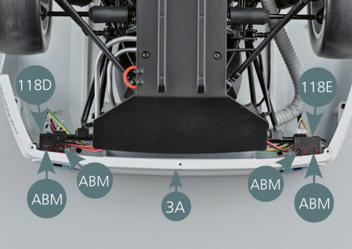
Positionner le capot avant 1A en faisant correspondre les goupilles situées sur la partie centrale de la carrosserie 93A avec les deux trous du capot (cercle jaune). Retourner l’ensemble et fixer les deux charnières 118D et 118E au pare-chocs avant 3A avec deux vis ABM pour chaque côté.
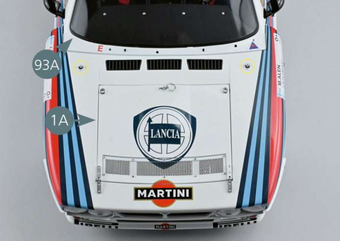
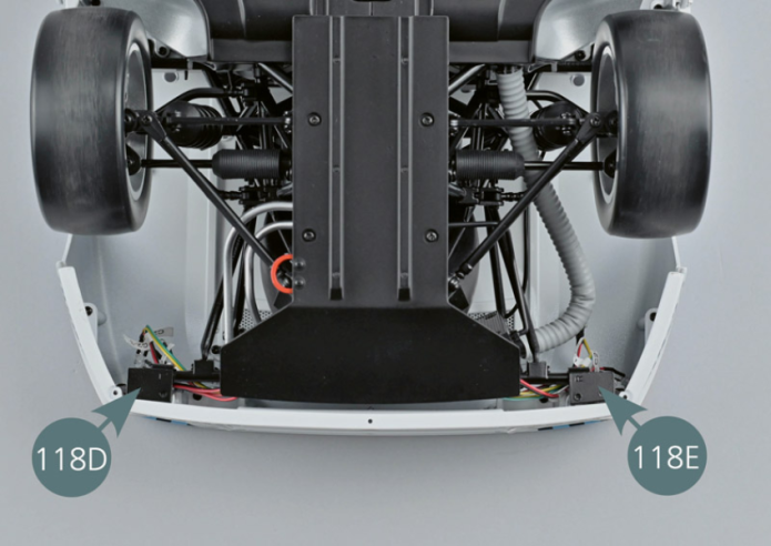
Position the front bonnet (1A) by matching the pins on the central part of the body (93A) with the two openings on the bonnet (yellow circle). Turn the assembly over and attach the two hinges (118D&118E) to the front bumper (3A) using two ABM screws on each side.
Etape 8


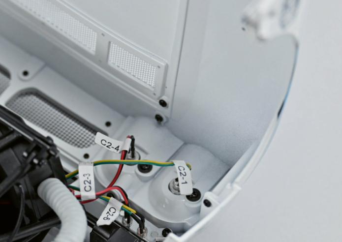
Ouvrir le capot 1A et insérer les LED de gauche comme indiqué. C2-1 : feu de croisement gauche ; C2-4 : feu de position gauche ; C2-5 : clignotant gauche ; C2-3 : feu de position gauche.
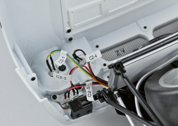
Insérer ensuite les LED de droite comme indiqué : C2-1 : feu de croisement droit ; C2-4 : feu de position droit ; C2-5 : clignotant droit ; C2-3 : feu de position droit.

Etape 9
Open the bonnet (1A) and insert the left LEDs as shown. C2-1: Left dipped headlight; C2-4: Left parking light; C2-5: Left indicator light; C2-3: Left parking light.
Then insert the right LEDs as shown: C2-1: right dipped headlight; C2-4: right parking light; C2-5: right indicator; C2-3: right parking light.

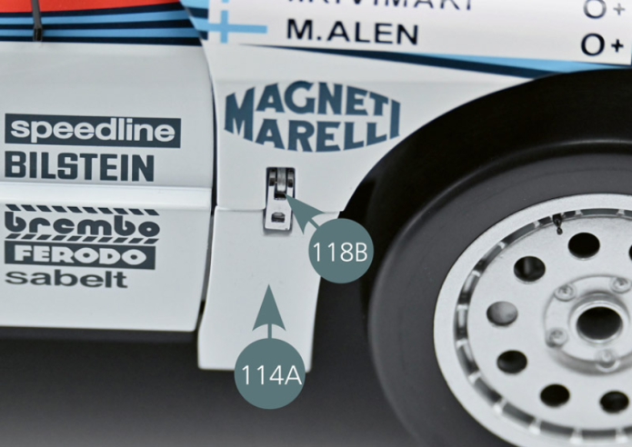
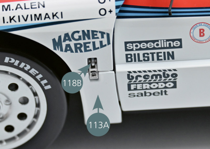
Refermer le capot et verrouiller l’attache du capot avant droite 118B sur la séparation capot-portière avant droite 114A. Verrouiller ensuite l’attache du capot avant gauche 118B sur la séparation capot-portière avant gauche 113A.

Etape 10
Re-close the bonnet and lock the right front bonnet fastener (118B) to the right front bonnet/door partition (114A). Then lock the left front bonnet fastener (118B) to the left front bonnet/door partition (113A).

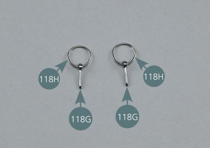
Insérer les anneaux de goupille de fixation du capot 118H dans les axes de goupille de fixation 118G.
Vue générale
Insert the bonnet retaining ring (118H) into the retaining clip pins (118G).
Kit 119 - Lame du pare-chocs avant
Parts of kit

Etape 1
- Screw TM M 1.7 x 4 mm (x 4)
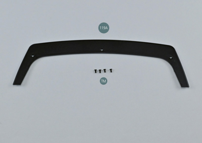
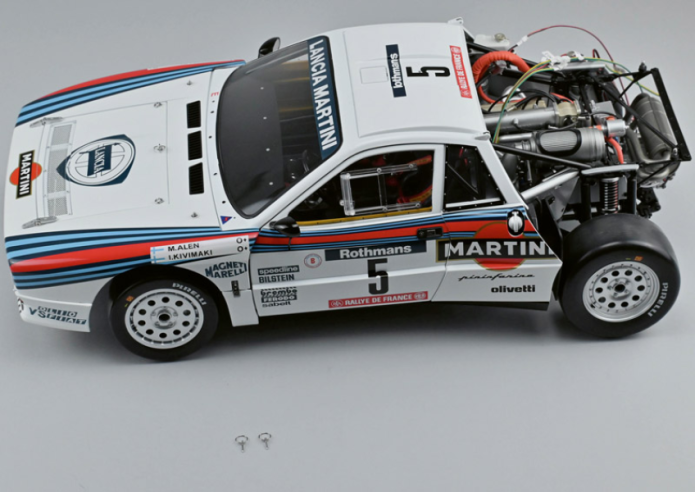
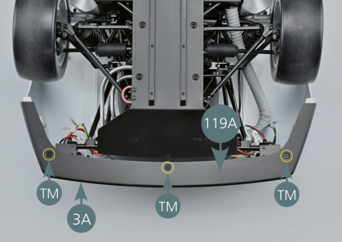
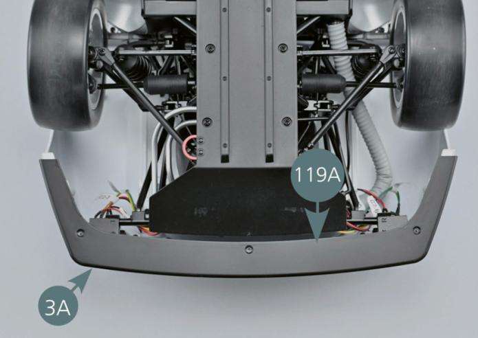
Retourner le modèle avec précaution. Positionner la lame du pare-chocs 119A, avec la face noire vers le haut, sur le pare-chocs 3A, et le fixer avec 3 vis TM.

Vue générale
Turn the model over with care. Position the bumper blade (119A), with the black side facing up, on the front bumper (3A), and secure it with 3 TM screws.

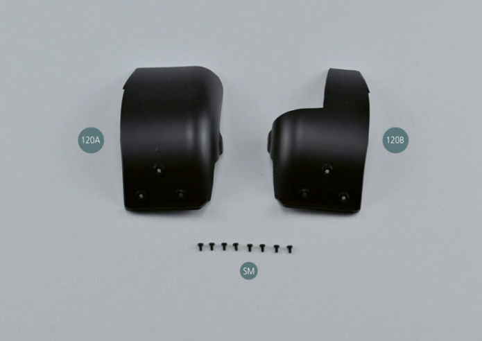
Kit 120 - Passages de roues avant
Parts of kit
Etape 1
- Screw SM M 1.7 x 3 mm (x 8)
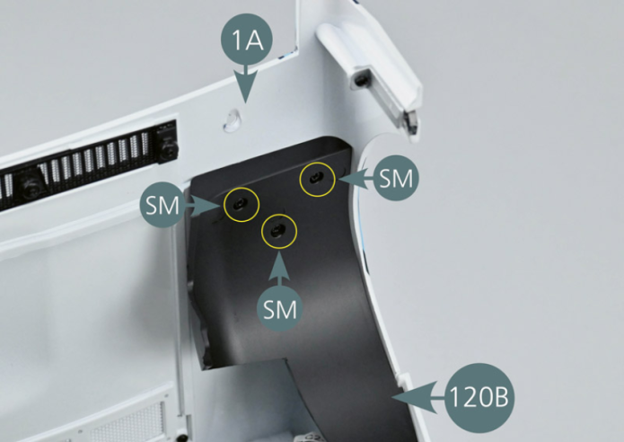
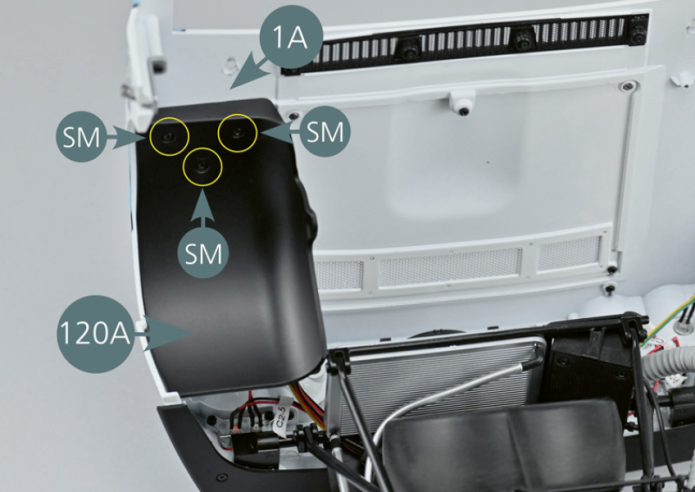
Ouvrir le capot avant 1A et positionner le passage de roue avant gauche 120A, en faisant correspondre les trois points de fixation comme indiqué (cercles jaunes). Fixer le passage de roue 120A avec trois vis SM.
Répéter l’opération pour le passage de roue avant droit 120B.

Etape 2
Open the front bonnet (1A) and install the left front wheel arch (120A), matching the three mounting points as shown (yellow circles). Secure the wheel arch (120A) with three SM screws.
Repeat the process for the right front wheel arch (120B).

Refermer le capot avant 1A et insérer l’axe de goupille de fixation 118G dans le trou du support de goupille de capot avant 117D, puis placer l’anneau de goupille 118H comme indiqué sur la photo.
Répéter l’opération pour la seconde goupille de fixation de l’autre côté du capot.
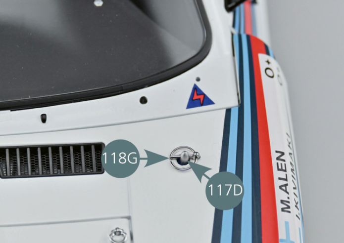
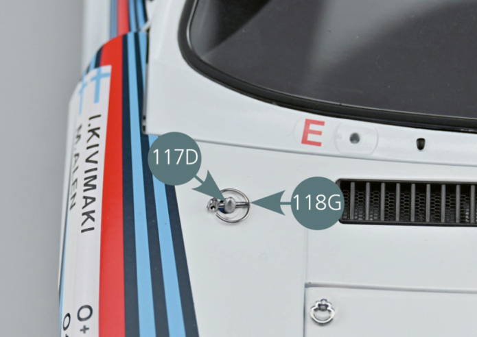
Vue générale
Close the front bonnet (1A) and insert the retaining clip pin (118G) into the opening in the front bonnet support pin (117D), then place the pin ring (118H) as shown in the photo.
Repeat the process for the second retaining pin on the other side of the bonnet.