English
 français
 Deutsch
 español
 italiano
 português


Box 10
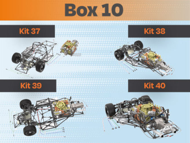
Kit 37
Parts of kit
- 37A Cockpit partition frame
- 37B Oil hose ( x2 )
- Screwdriver
- BM screw M 2,0 x4mm ( x5)

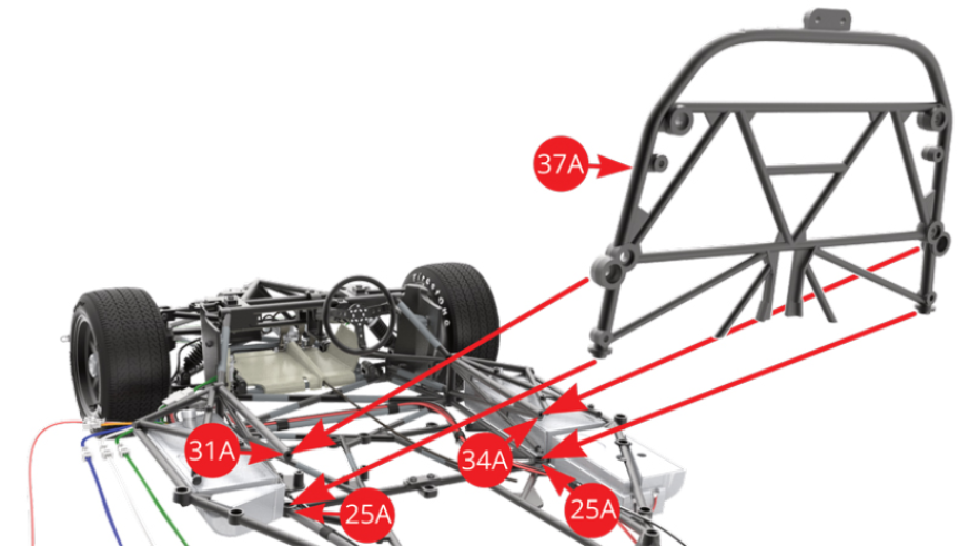
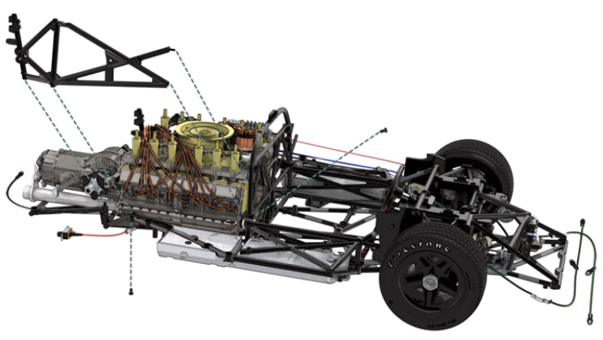
STEP 1
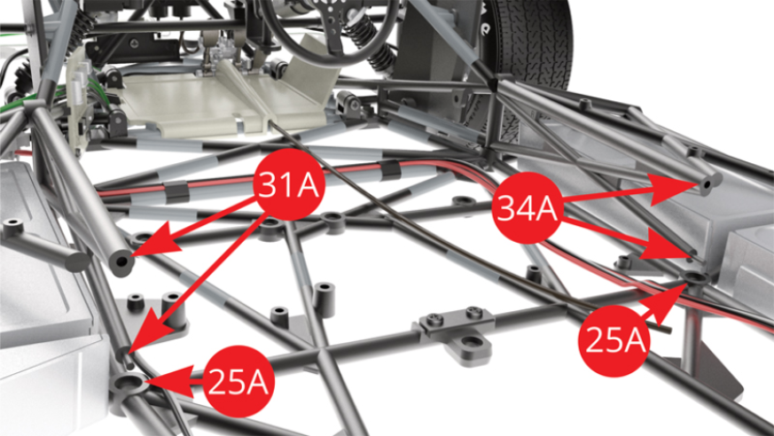
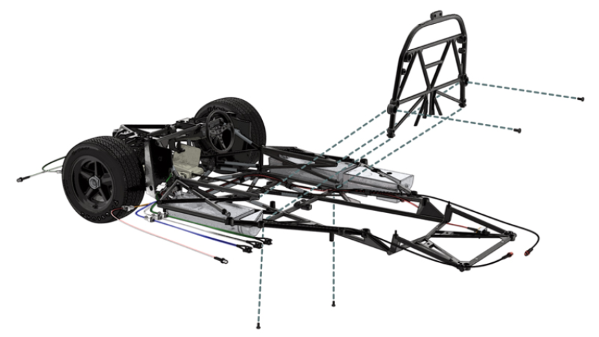
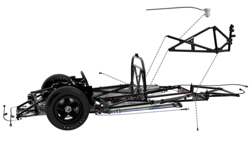
Fit 37A Cockpit partition frame to 25A Chassis lower frame sockets and 31A Left , 34A Right Side frames. Illustration below shows the attachment points on chassis in closer detail.
STEP 2
Fix 37A Cockpit partition frame to 31A Left and 34A Right Side frames with two BM screws.
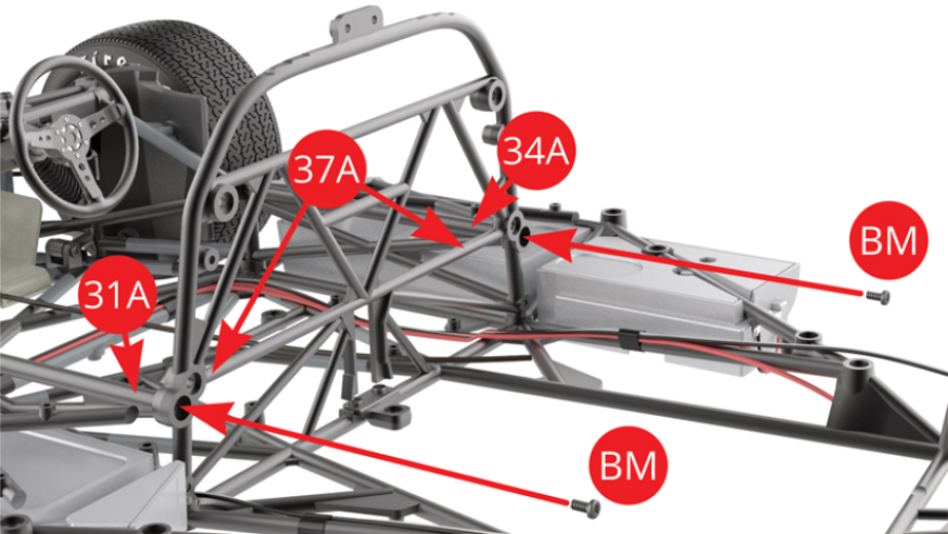
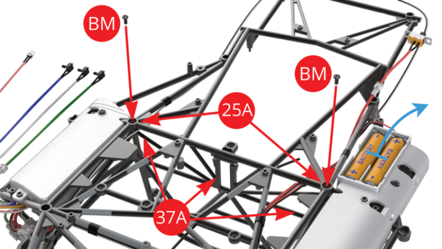
STEP 3
Fix 37A Cockpit partition frame to 25A Chassis lower frame with two BM screws. Take two AAA batteries out of battery compartment until further use.
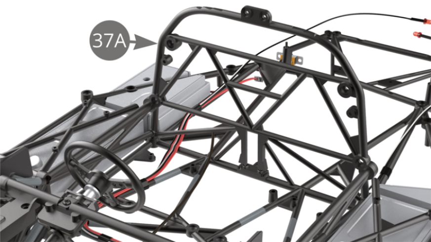
STEP 4
37A Cockpit partition frame installed on chassis .
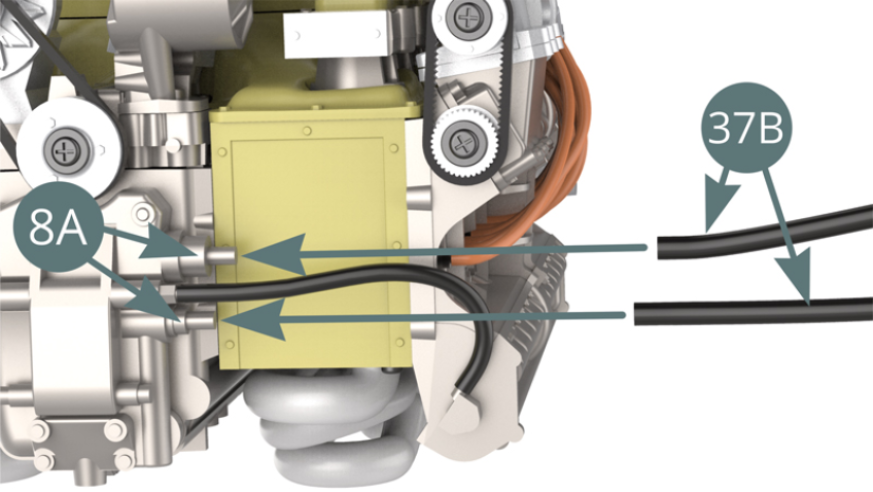
STEP 5
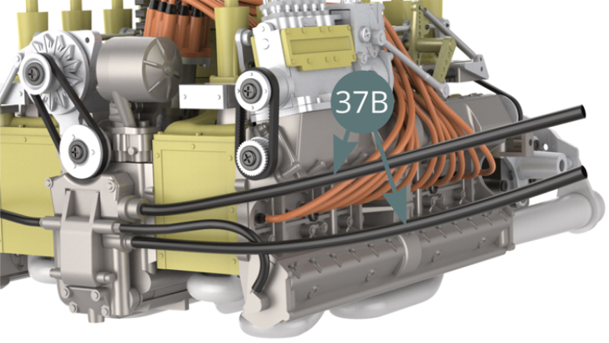
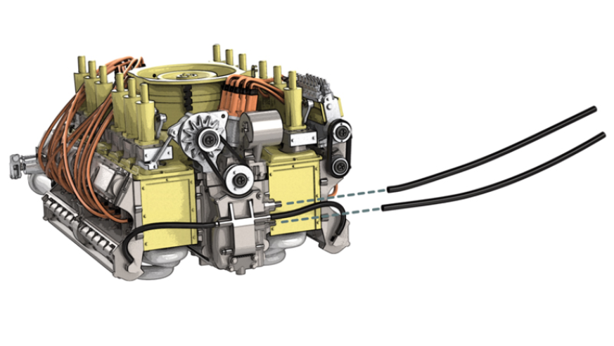
Fit two 37B Oil hoses to 8A Front cover pins
ASSEMBLY DIAGRAM
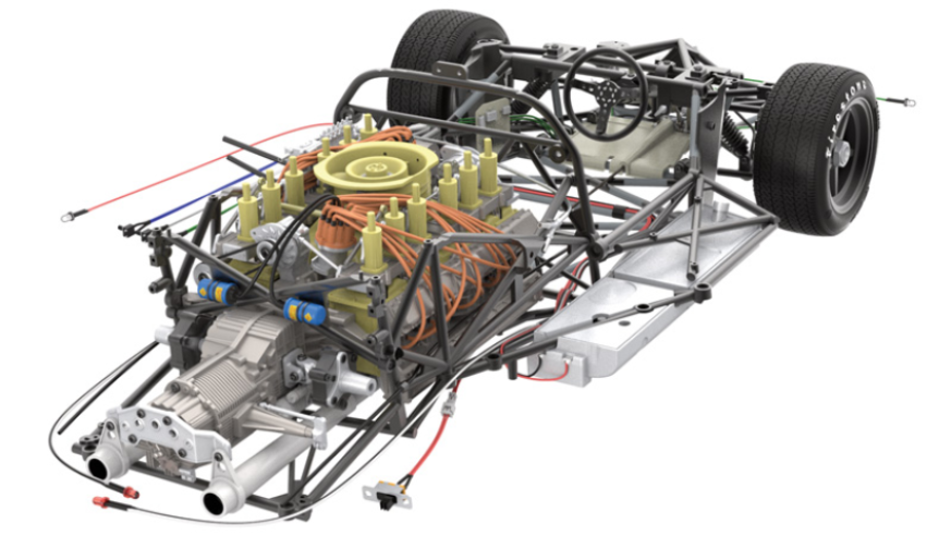
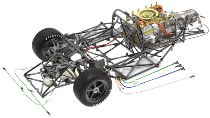
GENERAL VIEW

Kit 38
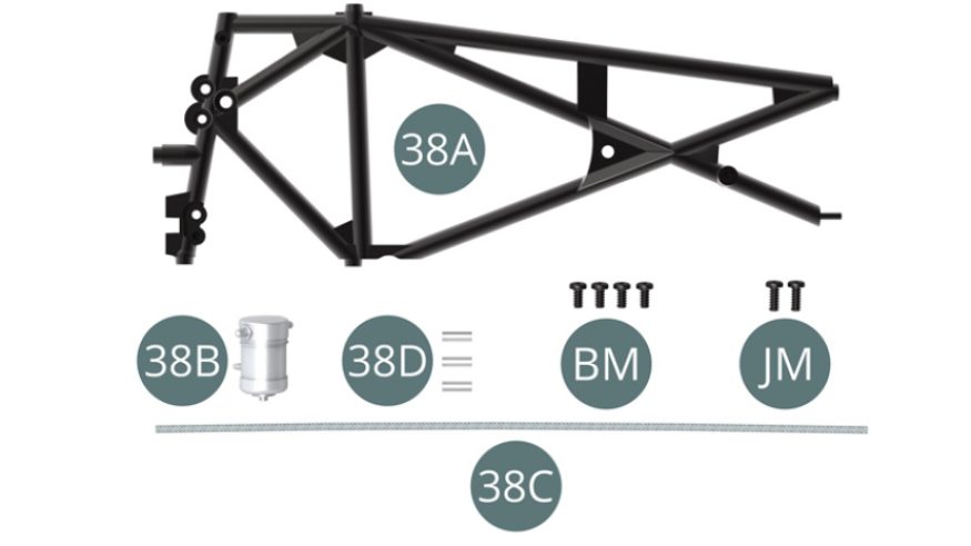
Parts of kit
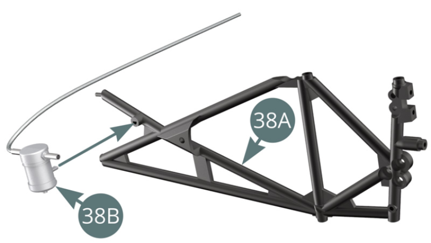
- 38A Left side frame
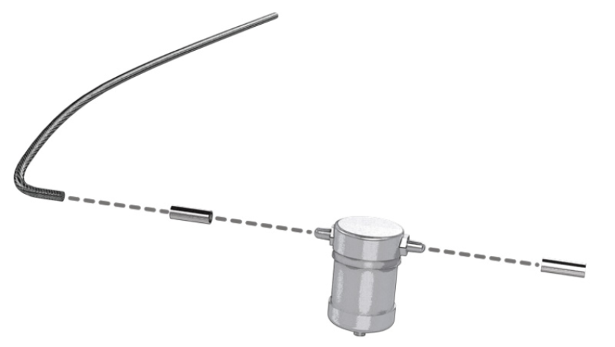
- 38B Fuel filter
- 38C Connectors ( x3 )
- 38D Fuel hose
- BM screw M2,0 x4mm ( x4 )
- JM screw M2,0 x5mm ( x2 )
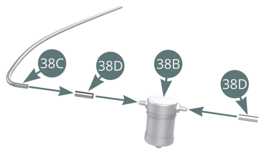
STEP 1
Fit two Connectors (38D) to Fuel filter (38B) pins. Fit Fuel hose (38xc) into Connector (38D) .
STEP 2
Fit Fuel filter (38B) to Left side frame (38A).
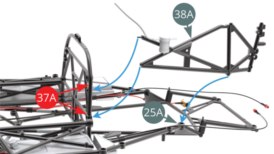
STEP 3
Fit 38A Left side frame (38A) to Cockpit partition frame (37A) and Chassis frame (25A) .
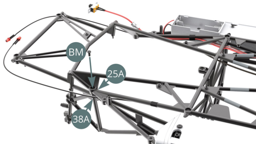
STEP 4
Fix Left side frame (38A) to Chassis frame (25A) with BM screw.
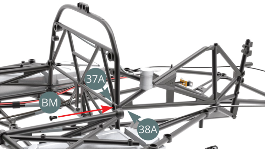
STEP 5
Fix Left side frame (38A) to Cockpit partition frame (37A) with BM screw.
STEP 6
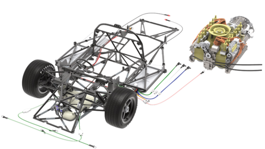
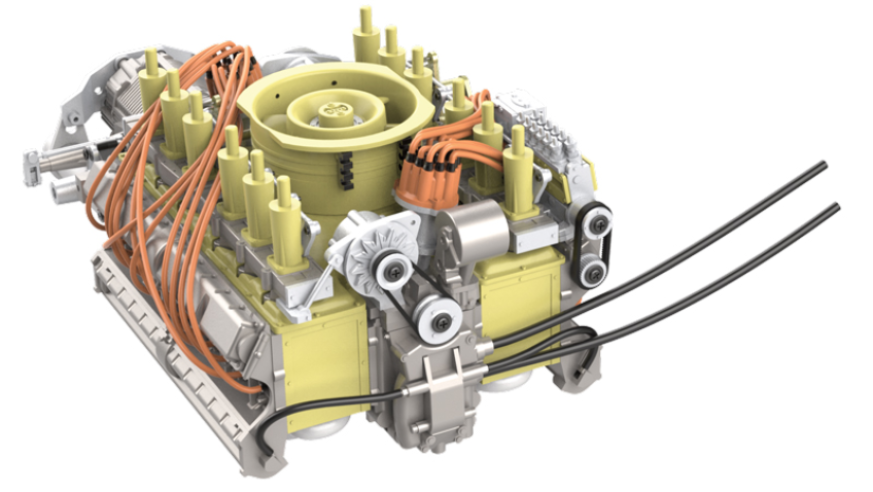
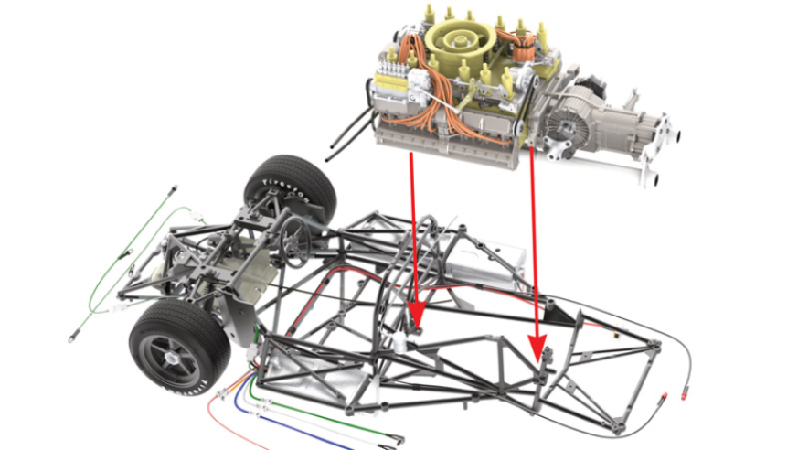
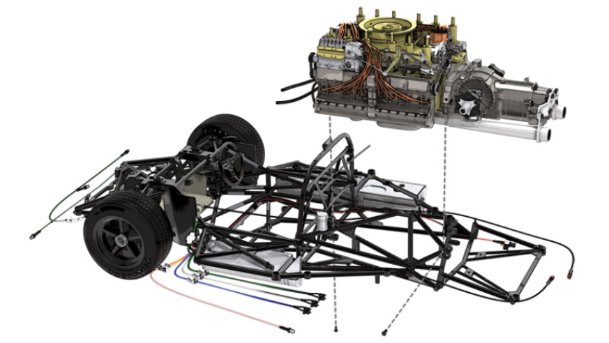
Fit Engine assembly to Chassis, aligning two immediate attachment points (red arrows). Lead Oil hoses (37B) as shown on next illustration.
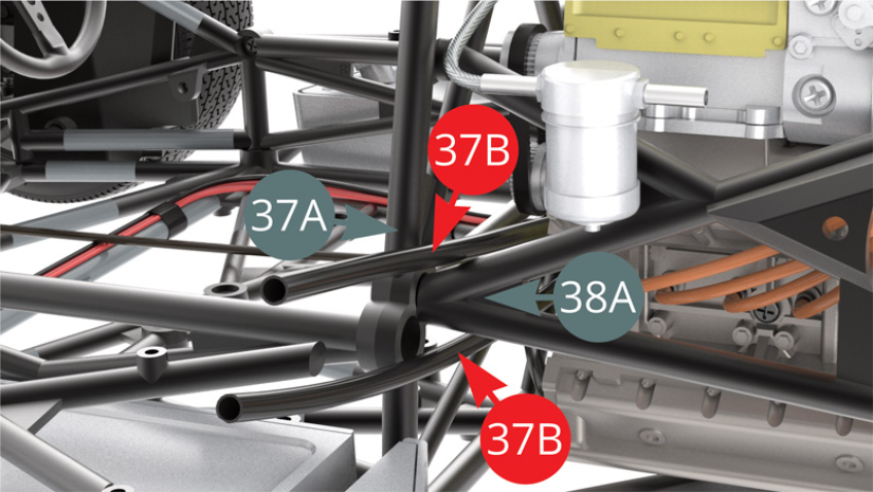
STEP 7
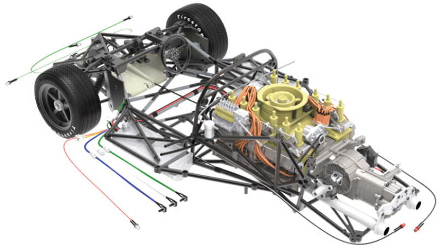
Pass the upper Oil hose (37B) above and the lower Oil hose (37B) below Left side frame V-bars (38A).
Upturn Chassis with Engine and fix Front Engine cover (8A) to Engine front (25A) mount with BM screw .
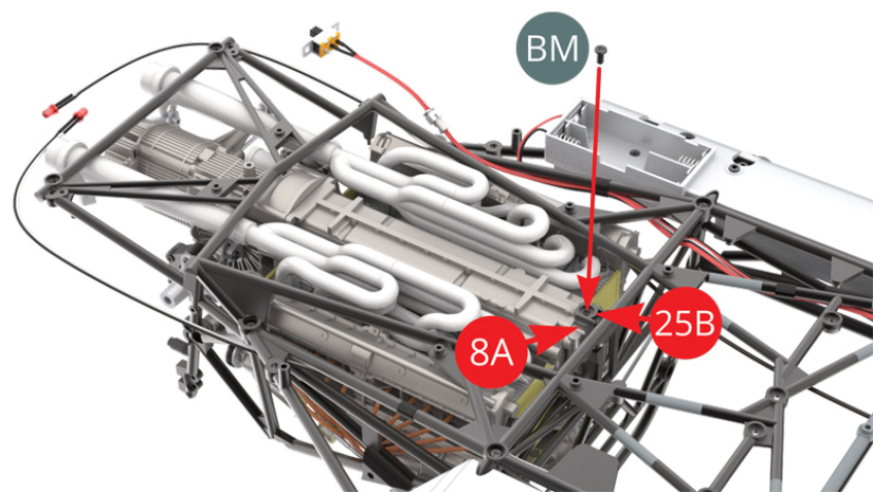
STEP 8
Upturn Chassis with Engine and fix Front Engine cover (8A) to Engine front (25A) mount with JM screw .
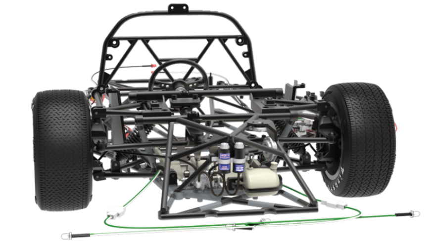
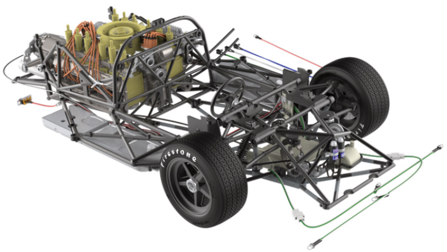
ASSEMBLY DIAGRAM
GENERAL VIEW
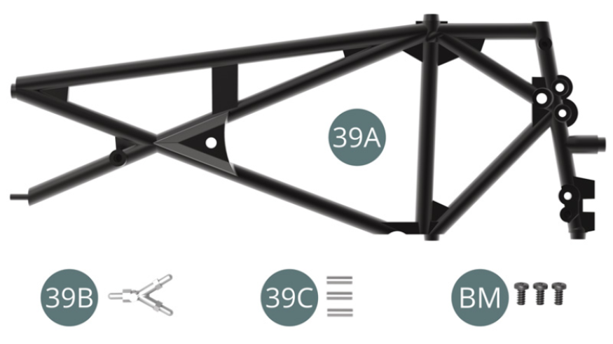
Kit 39
Parts of kit
- 39A Right side frame
- 39B Hose manifold
- 39C Connectors ( x3 )
- BM screw M2,0 x4mm ( x3 )
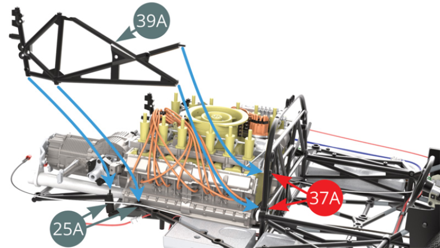
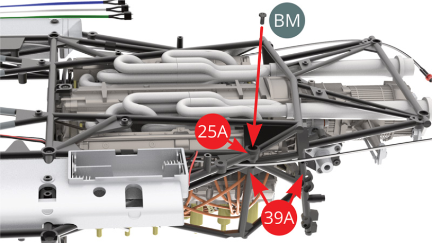
STEP 1
Fit Right side frame (39A) to Chassis frame (25A) and cockpit partition frame (37A) .
STEP 2
Fix Right side frame (39A) to cockpit partition frame (37A) with BM screw .
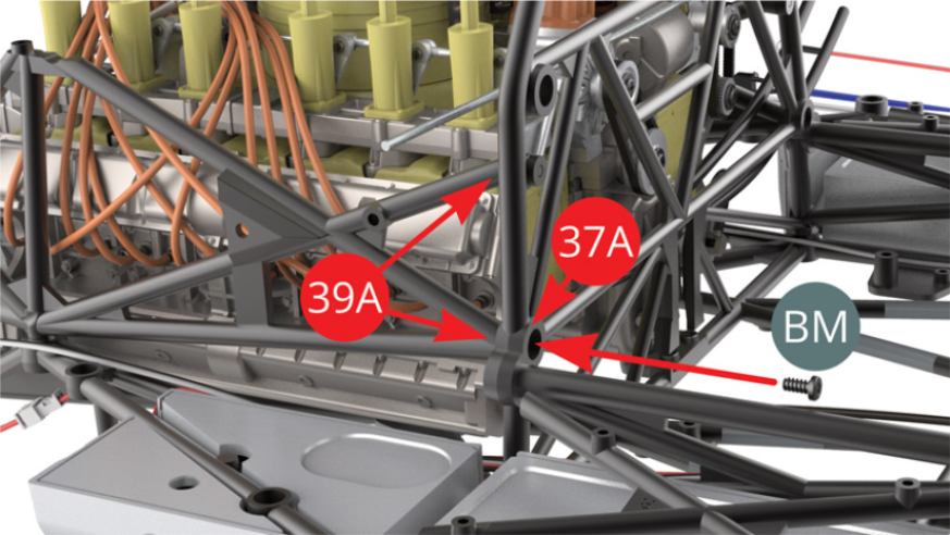
STEP 3
Fix Right side frame (39A) to Chassis frame (25A) with BM screw from under side of chassis .
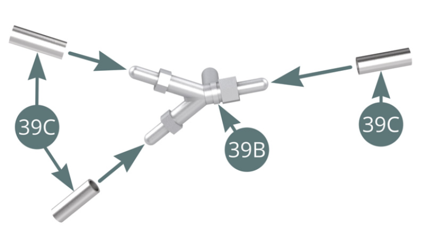
STEP 4
Fit three Connectors (39C) to Hose manifold (39B) .
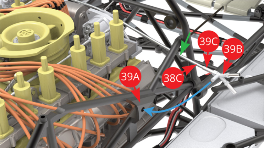
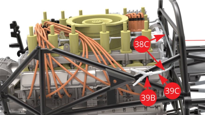
STEP 5
Fit Hose manifold (39B) by single Connector (39C) to 38C Fuel hose (38C) - pass Fuel hose (38C) below side frame bar - green arrow. Fit Hose manifold (39B) with attached Fuel hose (38C) to Right side frame (39A).
ASSEMBLY DIAGRAM
GENERAL VIEW
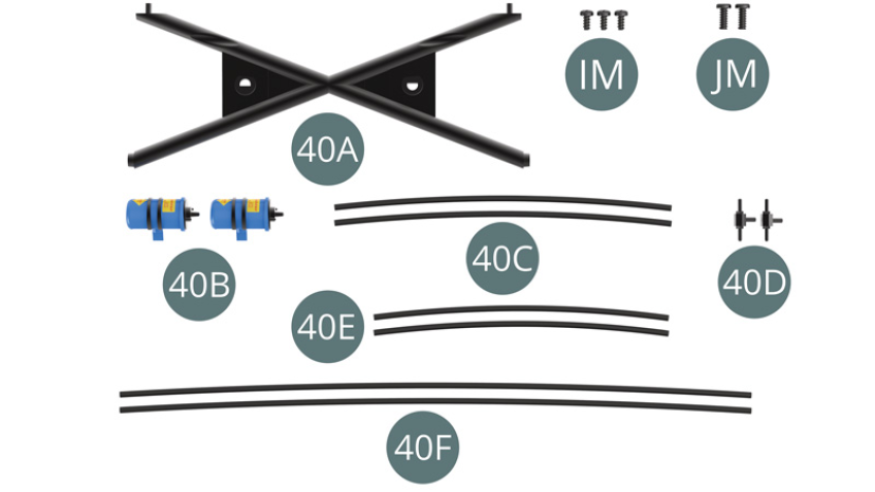
Kit 40
Parts of kit
- 40A X- Frame
- 40B Ignition coils ( x2 )
- 40C High tension cables ( x2 )
- 40D Connector ( x2 )
- 40E Brake line ( x2 )
- 40F Brake line ( x2 )
- IM screw M1,7 x3,5mm ( x3 )
- JM screw M2,0 x5mm ( x2 )
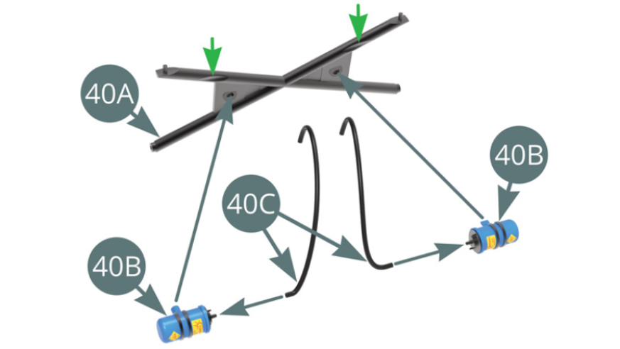
STEP 1
Fit High tension cables (40C) to both Ignition coils (40B) and fit them to X-frame (40A) - note notch orientation pointed by green arrows.
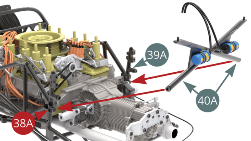
STEP 2
Fit 40A X-Frame (40A) to Left (38A) and 3 Right (39A) side frames.
STEP 3
Fix X-Frame (40A) to Left side frame (38A) with IM screw.
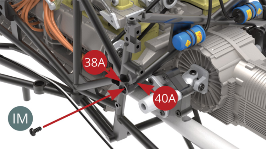
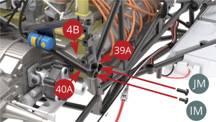
STEP 4
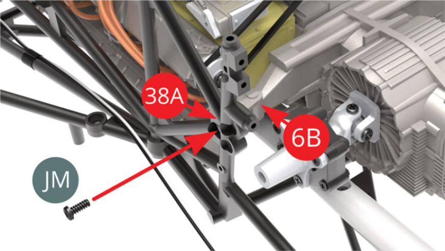
Fix X-Frame (40A) to Right side frame (39A) with IM screw. Fix Mounting arm (4B) to Right side frame (39A) with JM screw.
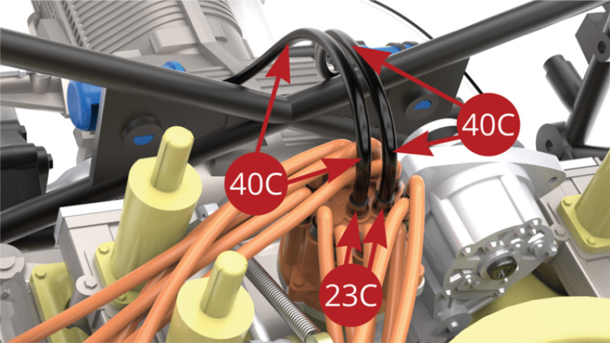
STEP 5
Fit both High tension cables ends (40C) on two Plugs (23C) .
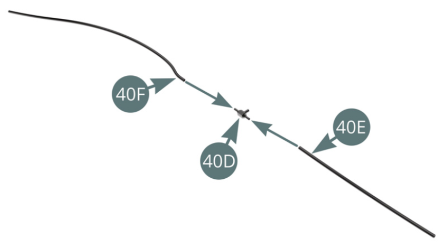
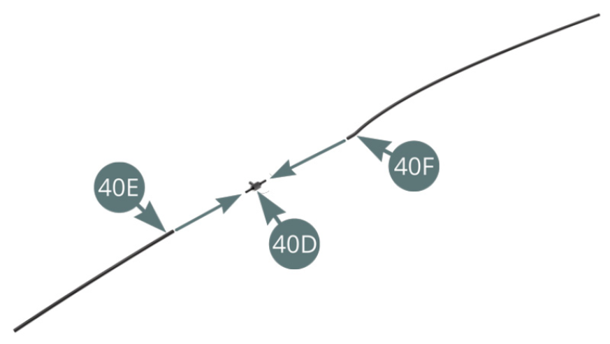
STEP 6
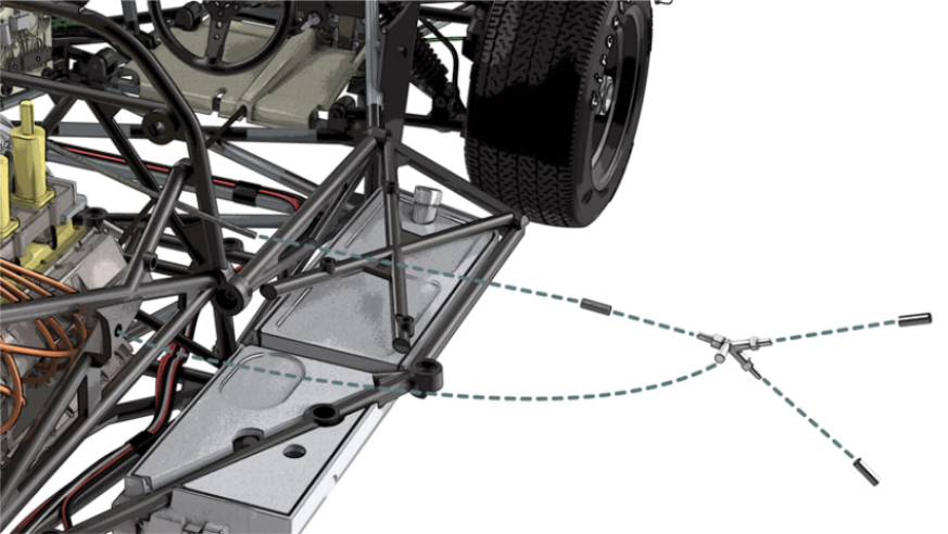
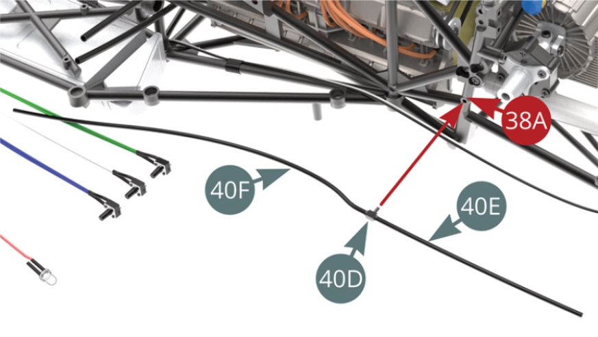
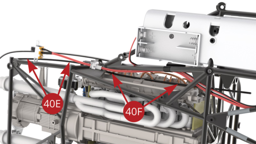
Fit and Brake lines (40E & 40F) to Connector (40D).
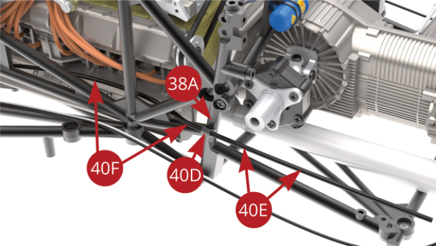
STEP 7
Fit Connector (40D) with attached Brake lines (40E & 40F) to 38A Left side frame bar (38A) - upper and lower illustrations.
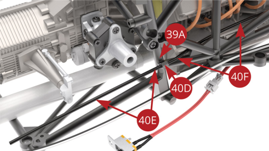
STEP 8
Fit Brake lines (40E & 40F) to Connector (40D). Fit Connector (40D) to 39A Right side frame bar (39A) - upper and two lower illustrations.
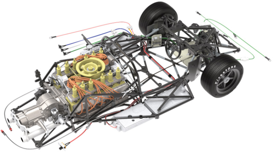
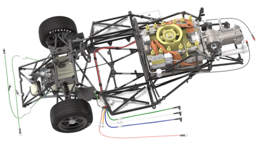
ASSEMBLY DIAGRAM
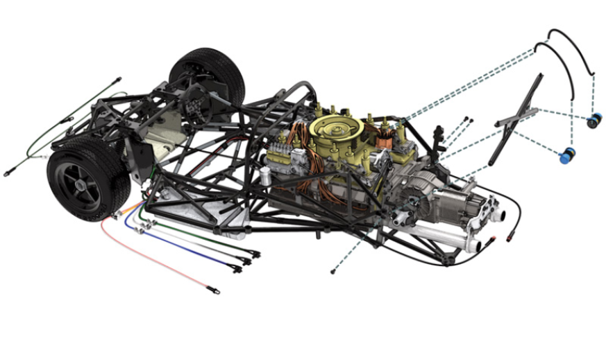
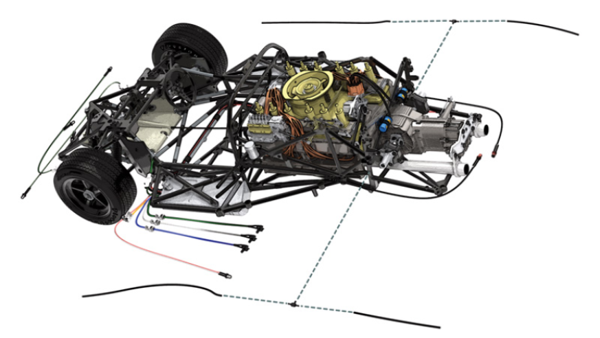
GENERAL VIEW