English
 français
 Deutsch
 español
 italiano
 português


Box 12
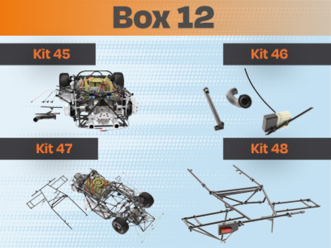
Kit 45
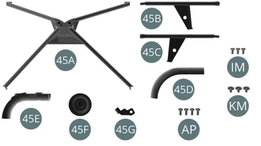
Parts of kit
- 45A Reinforcement frame
- 45B Left-hand stand
- 45C Right-hand stand
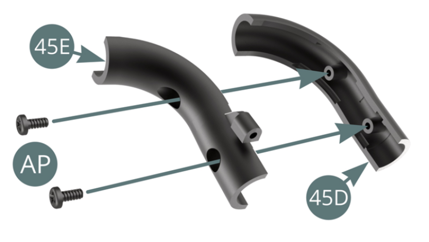
- 45D Transmission cooling line
- 45E Transmission cooling line
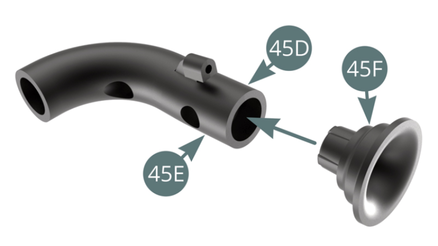
- 45F Pipe outlet
- 45G Support bracket
- AP Screw M 1.7 x 4 mm (x 4)
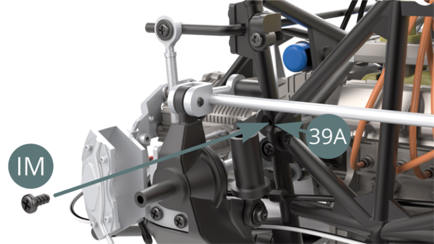
- IM Screw M 1.7 x 3.5 mm (x 3)
- KM Screw M 1.7 x 3 x 5 mm (x 3)
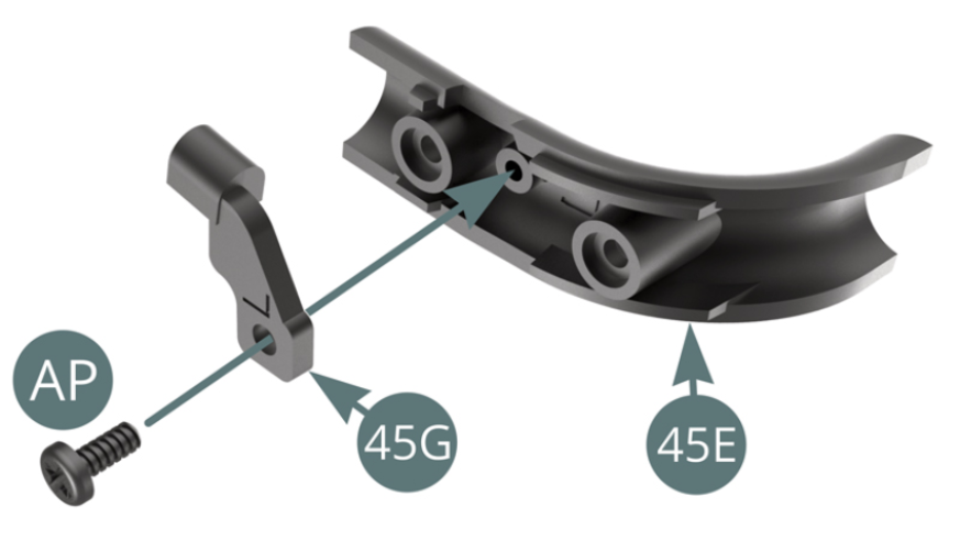
STEP 1
Position the Pipe Outlet (45F) on the 45E-45D assembly. Position the Support bracket (45G) on the line (45E) and secure it with an AP screw.
Connect the two Cooling line halves (45E and 45D) and secure with two AP screws.
STEP 2
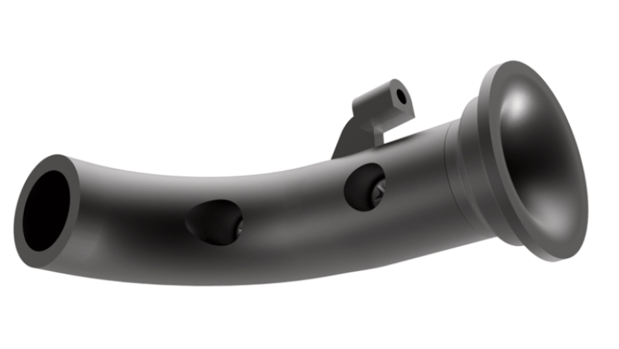
Position the Pipe Outlet (45F) on the 45E-45D assembly.
STEP 3
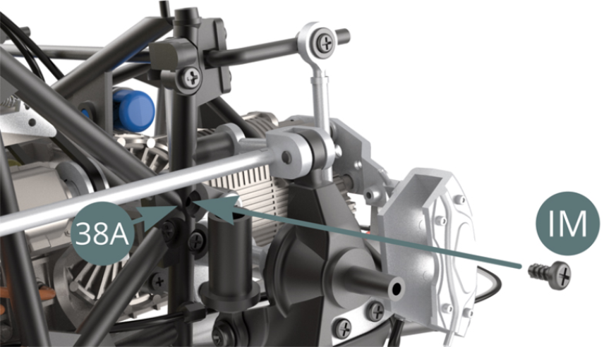
Position the Reinforcement frame (45A) on the Lower frame (25A) and on the left (38A) and right (39A) Side frames.
Fix the Reinforcement Frame (45A) to the left (38A) and right (39A) Side frames with two IM screws as shown in the two illustrations below.

Right side
Left side
STEP 4
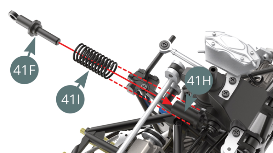
Position the Suspension Spring (41I) on the Damper (41H) - red dotted arrows. Position the Suspension piston rod (41F) into the Damper cylinder (41H) by passing it through the spring (41I).
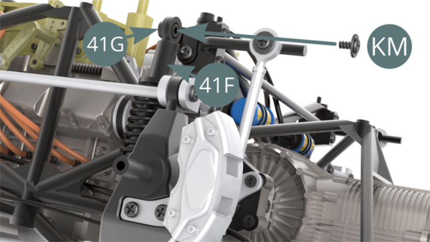
Position the Suspension piston rod head (41F) on the end of the bracket (41G) and secure it with a KM screw.
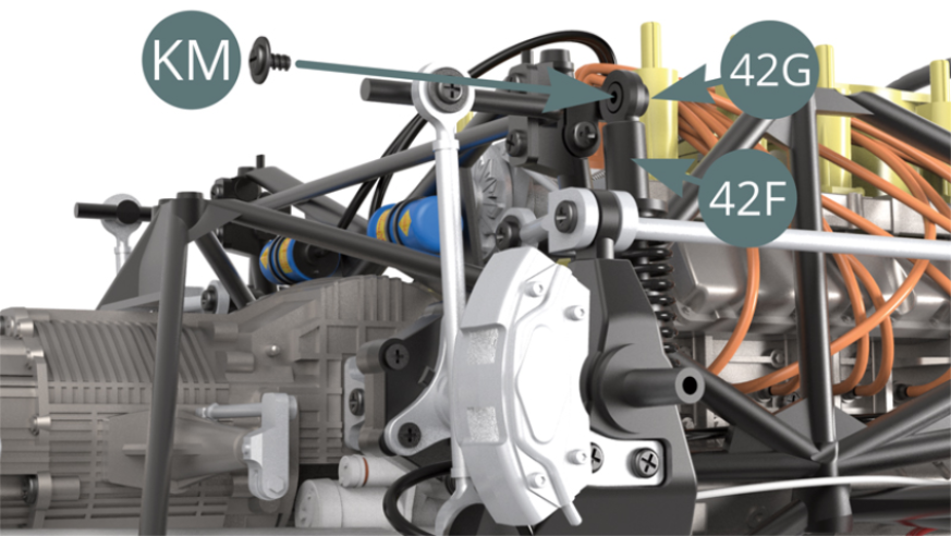
STEP 5
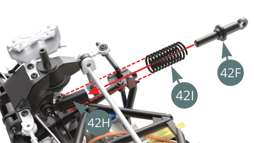
Position the Suspension spring (42I) on Damper (42H) - red dotted arrows. Position the Suspension piston rod (42F) into the Damper (42H) through the Spring (42I).
Position the Suspension piston rod (42F) on the end of the Bracket (42G) and secure it with a KM screw.
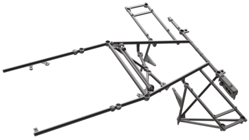
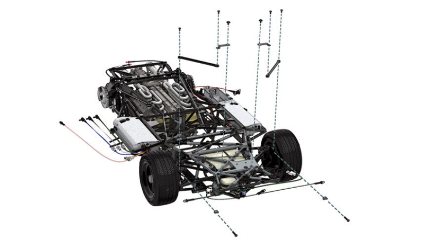
ASSEMBLY DIAGRAM
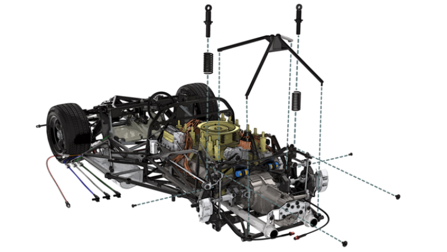
GENERAL VIEW
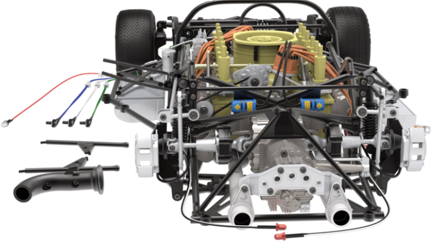
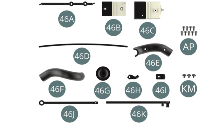
Kit 46
Parts of kit
- 46A Strut
- 46B Engine oil recovery tank
- 46C Tank cover
- 46D Engine oil recovery hose
- 46E Transmission cooling line
- 46F Transmission cooling line
- 46G Line outlet
- 46H Support bracket
- 46I Bonnet - Arm Support
- 46J Bonnet - Lift arm
- 46K Bonnet - Lift arm
- AP Screw M 1.7 x 4 mm (x 9)
- KM Vis M 1.7 x 3 x 5 mm (x 3)
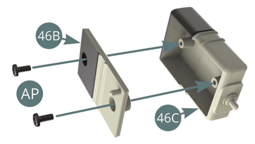
STEP 1
Position the Cover (46C) on the Engine oil recovery tank (46B) and secure with two AP screws.
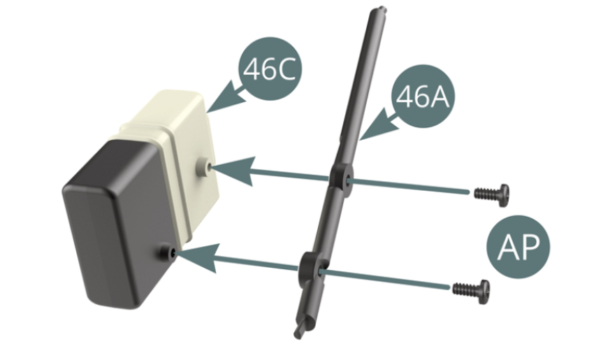
Position the Strut (46A) on the Engine oil recovery tank (46B) and secure with two AP screws.
STEP 2
Position the Engine oil recovery hose (46D) on the Tank cover (46B).
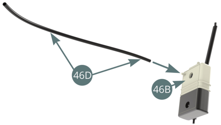
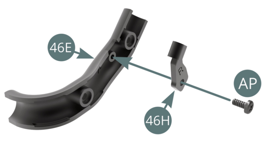
Position the Bracket (46H) on the line (46E) and secure it with an AP screw.
STEP 3
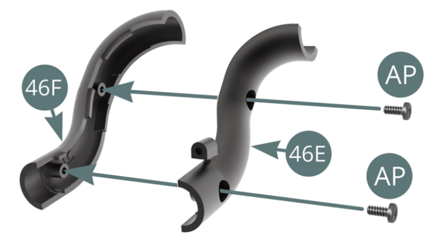
Connect the two Cooling line halves (46F and 46E) and secure them with two AP screws.
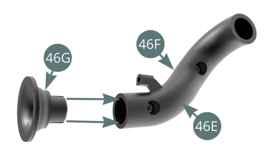
Position the Line outlet (46G) on the 46E-46F assembly.
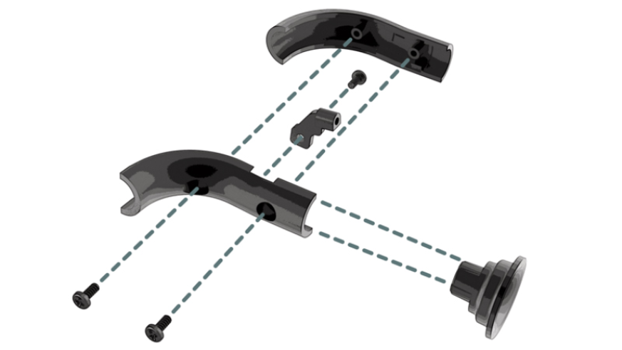
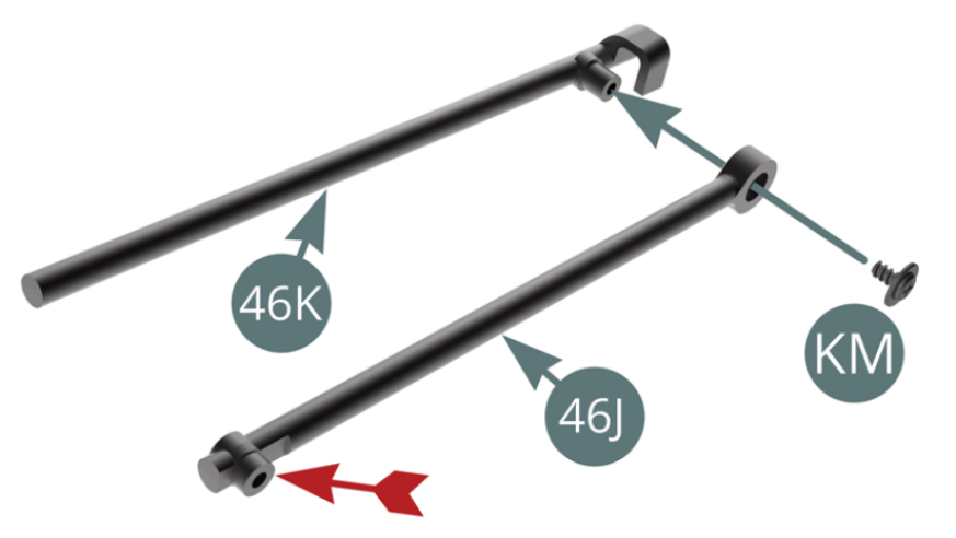
STEP 4
Position the Lift arm (46J) on the Lift arm (46K) - note the orientation of the free end indicated by the red arrow - and secure it with a KM screw.
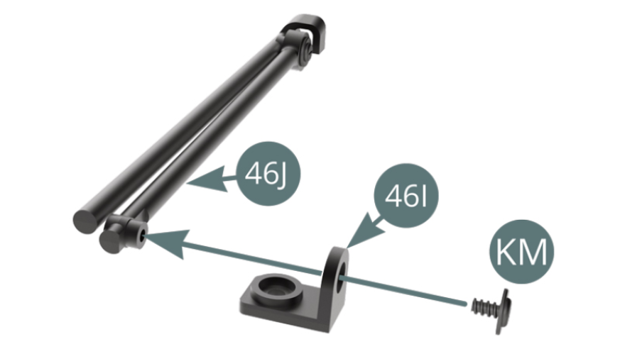
Position the Bracket (46I) on the Bonnet lift arm (46J) and secure with a KM screw.
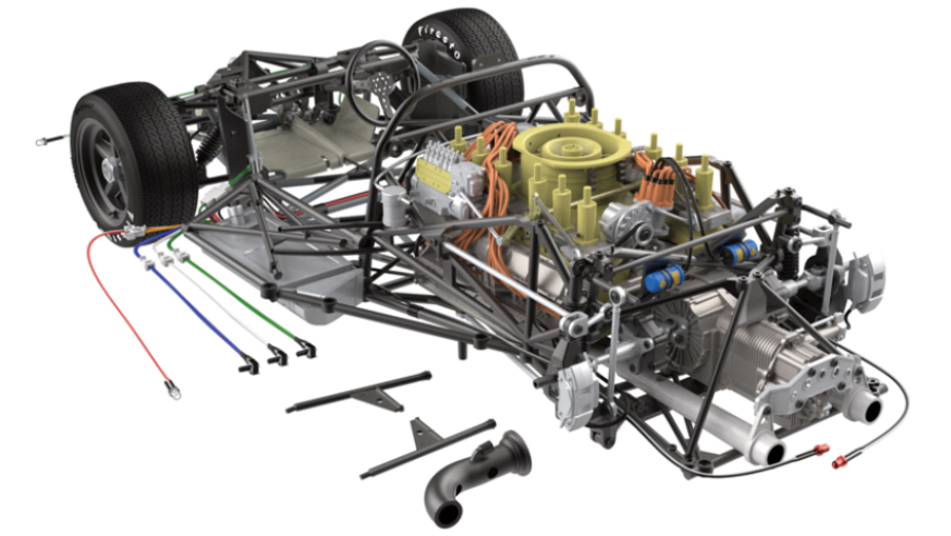
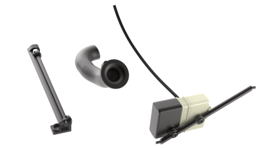
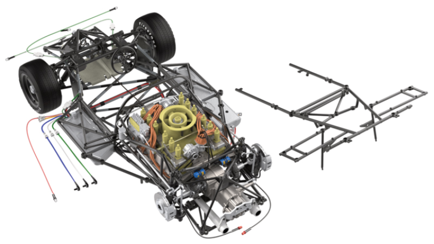
ASSEMBLY DIAGRAM
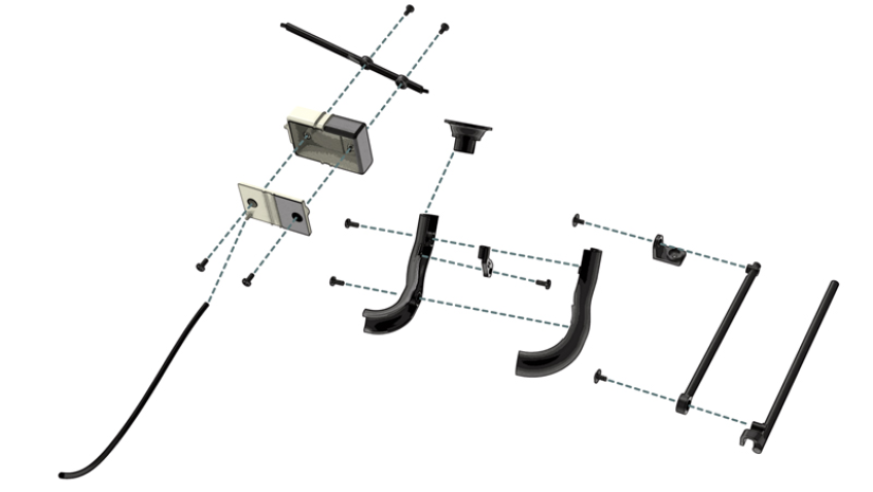
GENERAL VIEW

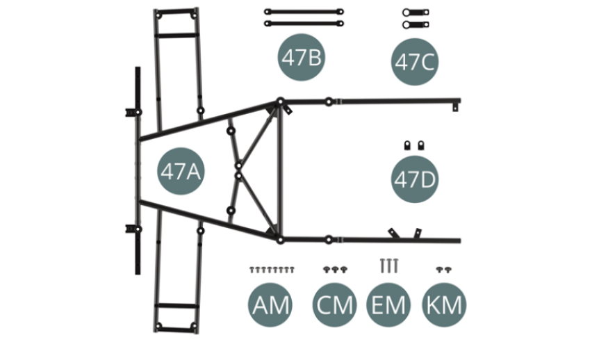
Kit 47
Parts of kit
- 47A Upper frame
- 47B Front lower strut (x 2)
- 47C Bracket (x 2)
- 47D Bracket (x 2)
- AM Screw M 1.7 x 3 mm (x 8)
- CM Screw M 2.0 x 3 x 5 mm (x 3)
- EM Screw M 2.0 x 9 mm (x 3)
- KM Screw M 1.7 x 3 x 5 mm (x 2)
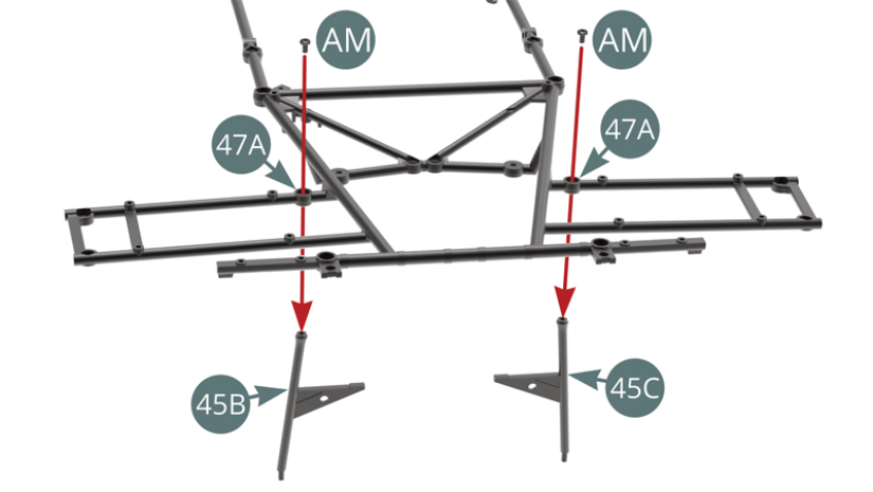
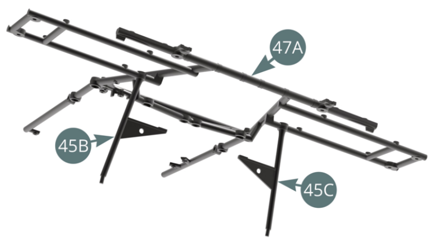
STEP 1
Position the left stand (45B) and right stand (45C) on the Upper frame (47A) and secure each with an AM screw (see illustrations opposite and below).
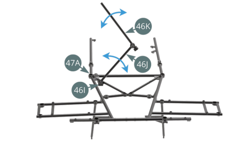
STEP 2
Position the Bonnet lift arm (46K-46J) on the Upper frame (47A) via the bracket 46I and secure with a KM screw.
Check that the lift arms (46K-46J) fold and unfold correctly (blue arrows) as shown in the picture.

STEP 3
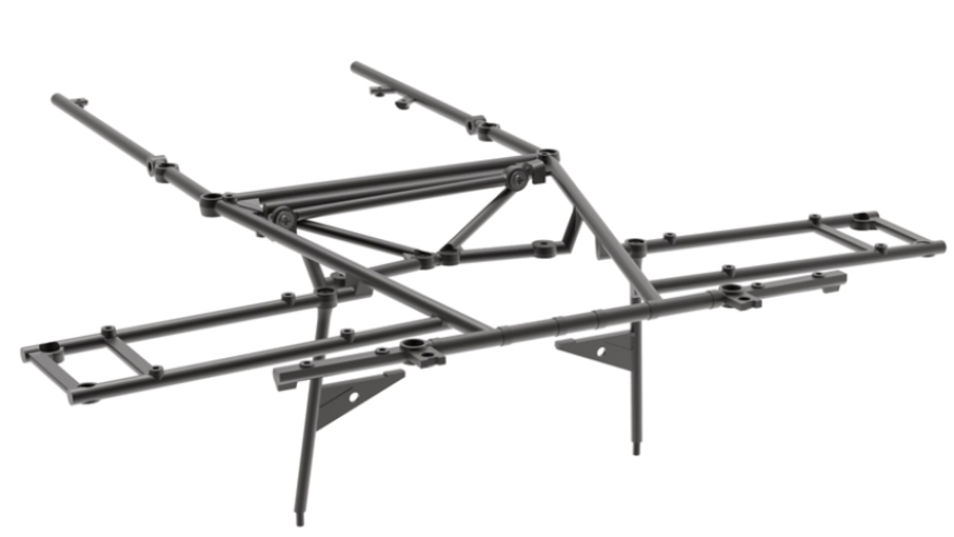
Pre-assembled upper frame
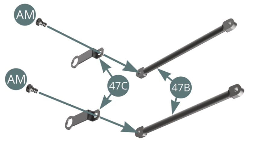
Position a Bracket (47C) on each Front lower strut (47B) and secure with an AM screw.
STEP 4
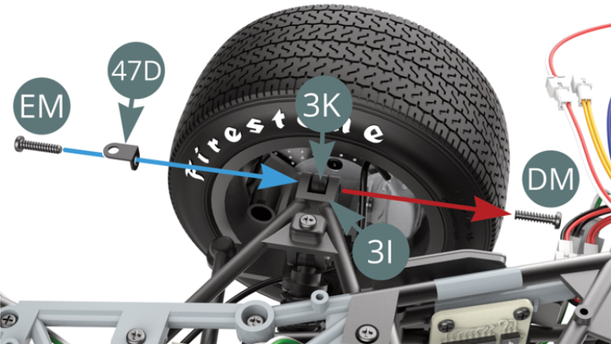
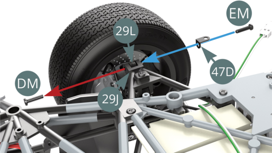
Unscrew the DM screw from the left upright joint 3I & 3K (red arrow) and secure it on the other side with an EM screw by attaching the Bracket (47D) - blue arrow.
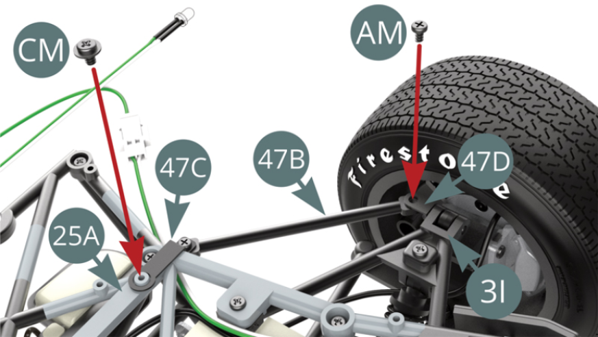
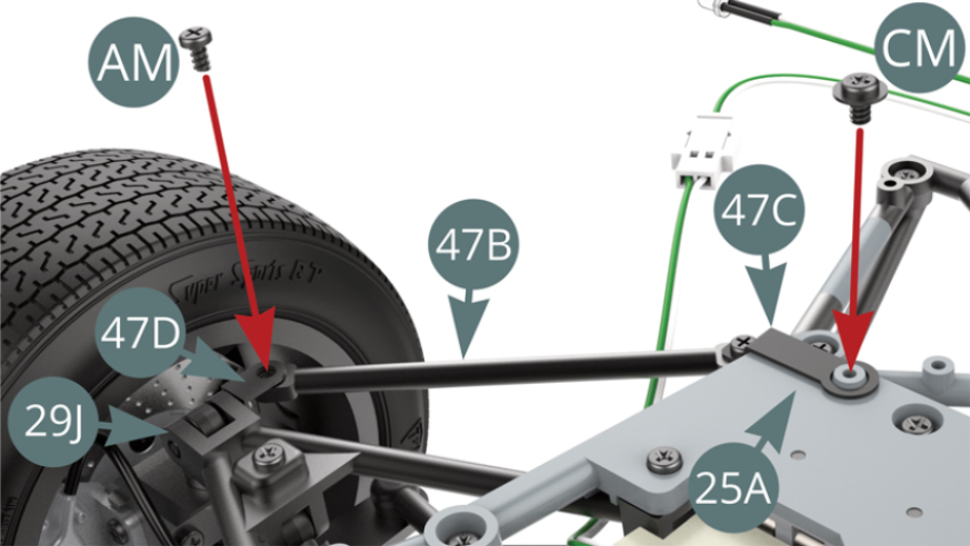
Position the free end of the Front lower strut (47B) on the Bracket (47D) and the Bracket (47C) of the other end on the Lower frame (25A). Then fix them with an AM and CM screw respectively (under the left side).
STEP 5
Unscrew the DM screw from the Left upright joint (3J-3L) - red arrow - and secure it on the other side with an EM screw by attaching the Bracket (47D) - blue arrow.
Position the free end of the Front lower strut (47B) on the Bracket (47D) and the Bracket (47C) of the other end on the Lower frame (25A). Then fix them with a screw AM and CM respectively (under the right side).
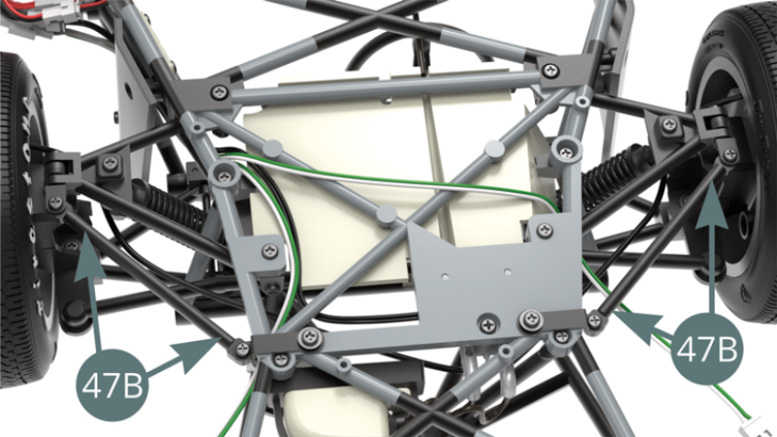
Front lower struts (47B) installed on the front suspension, view from below
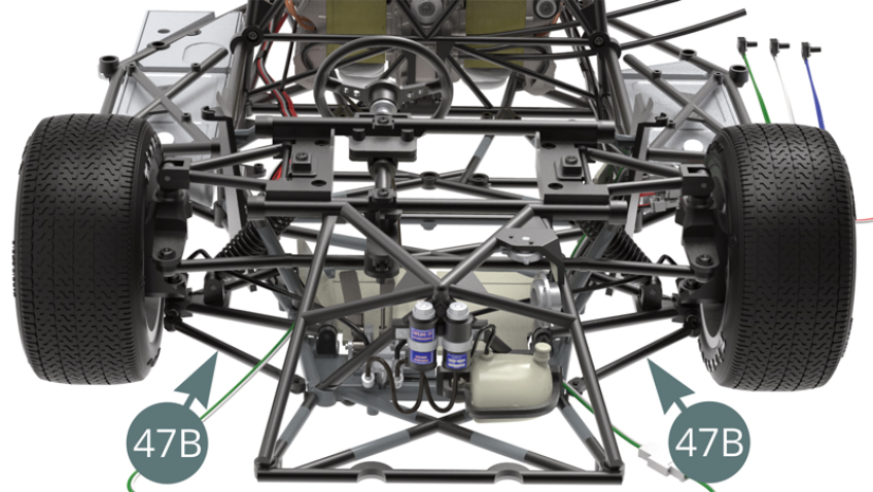
Front lower struts (47B) installed on the front suspension, top view
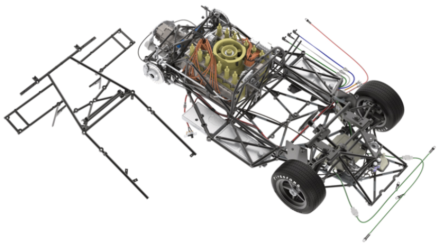
ASSEMBLY DIAGRAM

GENERAL VIEW
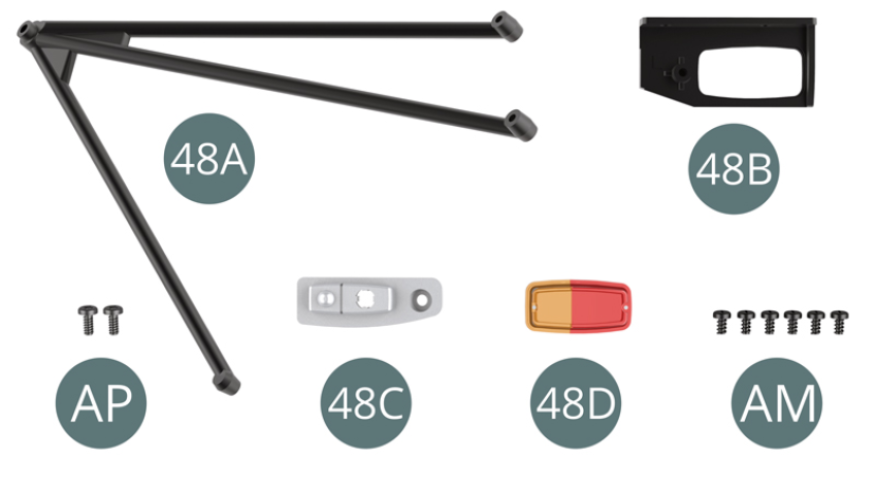
Kit 48
Parts of kit
- 48A Left tripod bar
- 48B Left tail light housing
- 48C Left tail light reflector
- 48D Left tail light
- AM Screw M 1.7 x 3 mm (x 6)
- AP Screw M 1.7 x 4 mm (x 2)
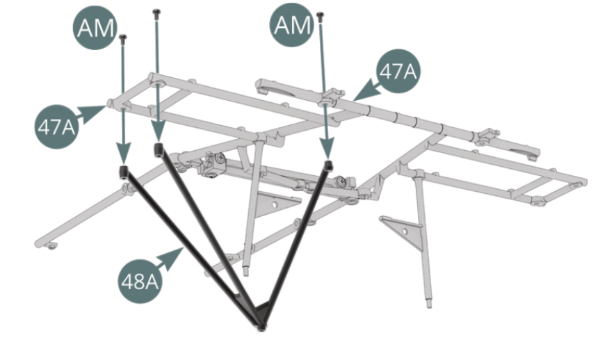
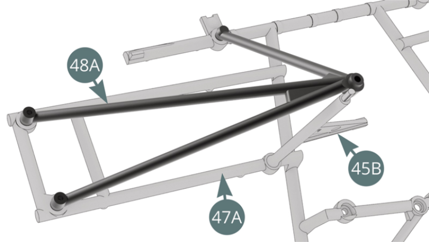
STEP 1
Position the Left Tripod Bar (48A) on the Top frame (47A) and secure with three AM screws (shown opposite and below).
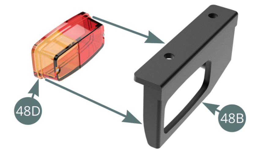
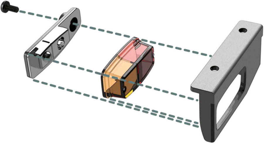
STEP 2
Position the Left tail light (48D) in the housing (48B).
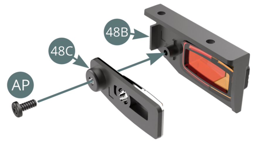
Position the Reflector (48C) on the Left tail light housing (48B) and secure it with an AP screw.
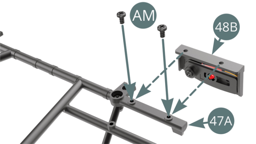
STEP 3
Position the left tail light housing (48B) on the right rear end of the Upper frame (47A) and secure with two AM screws (shown opposite).

ASSEMBLY DIAGRAM
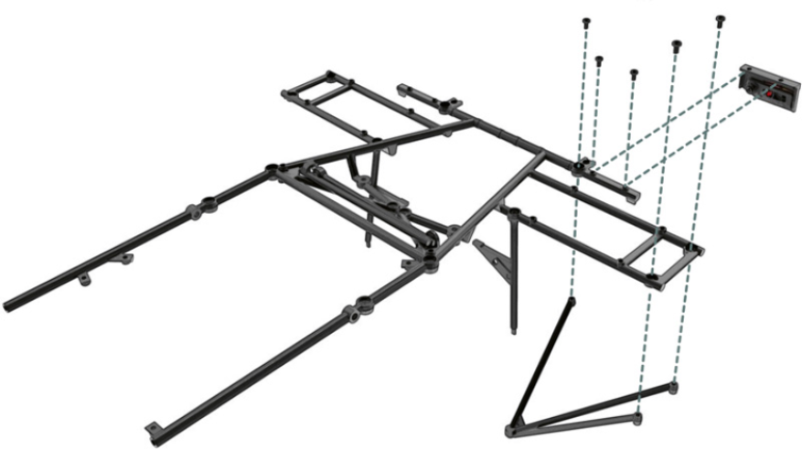
GENERAL VIEW