English
 français
 Deutsch
 español
 italiano
 português


Box 13
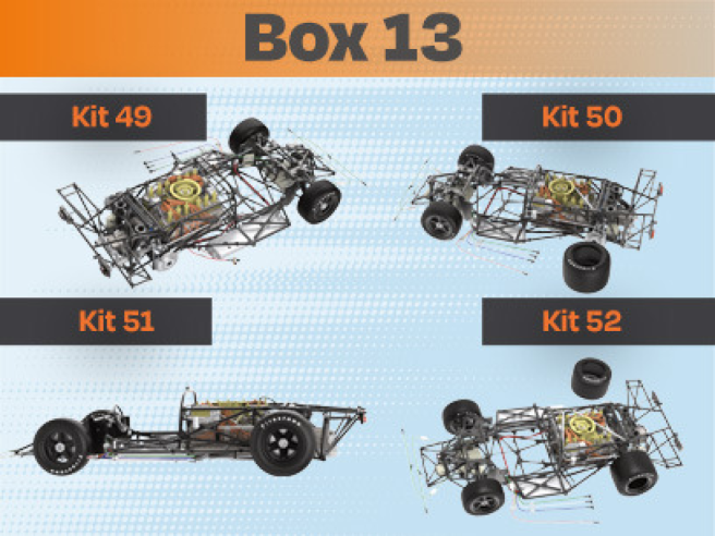
Kit 49
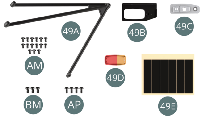
Parts of kit
- 49A Right tripod bar
- 49B Right tail light housing
- 49C Right tail light reflector
- 49D Right tail light
- 49E Adhesive tape (x 6)
- AM Screw M 1.7 x 3 mm (x 15)
- AP Screw M 1.7 x 4 mm (x 4)
- BM Screw M 2.0 x 4 mm (x 3)
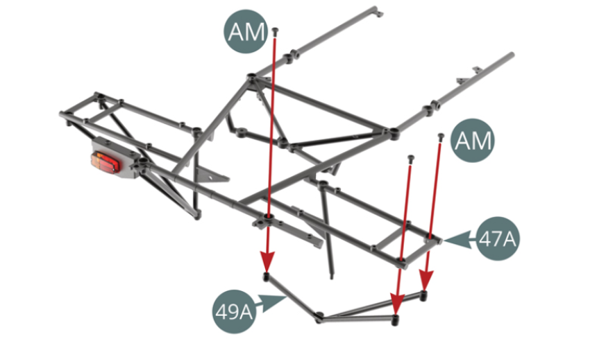
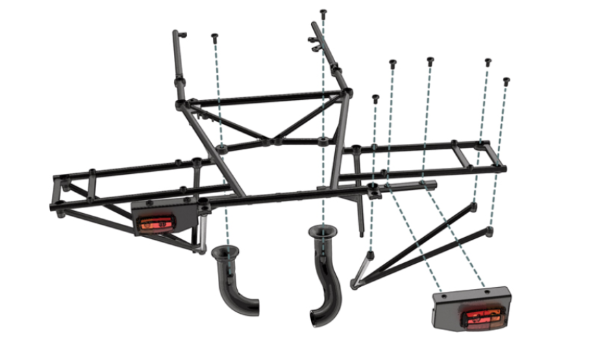
STEP 1
Position the right tripod bar (49A) on the upper frame (47A) and secure it with three screws AM.
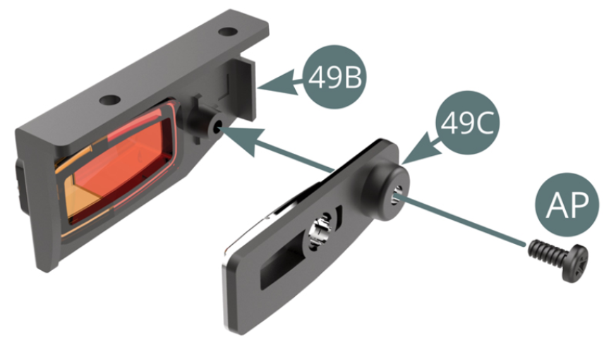
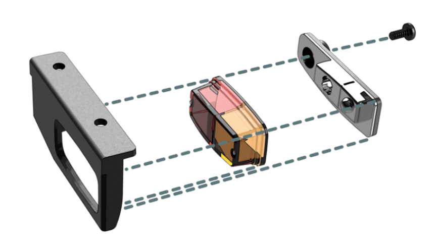
Position the right rear light (49D) into the housing (49B)

STEP 2
Position the reflector (49C) onto the right rear light housing (49B) and secure with one AP screw.
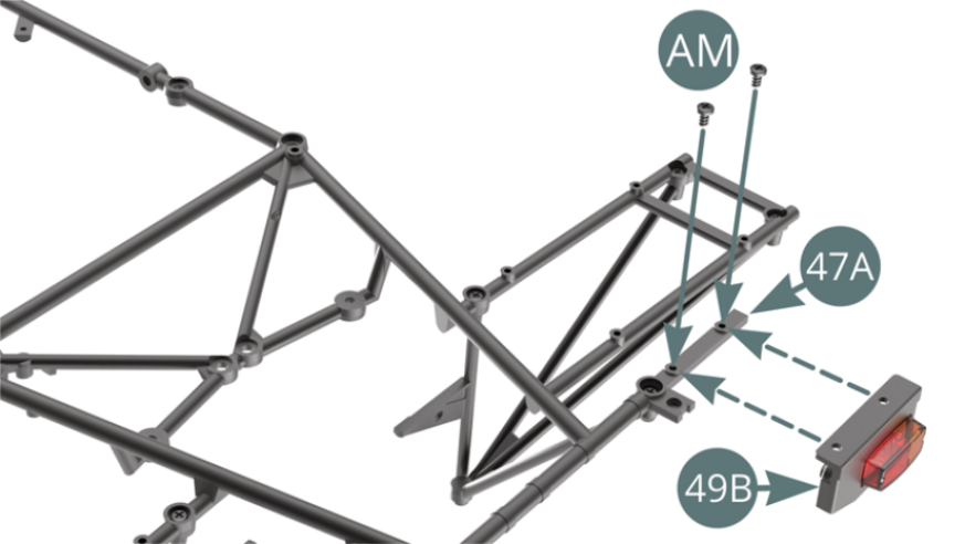
Position the right rear light housing (49B) on the right rear end of the upper frame (47A) and secure with two AM screws.
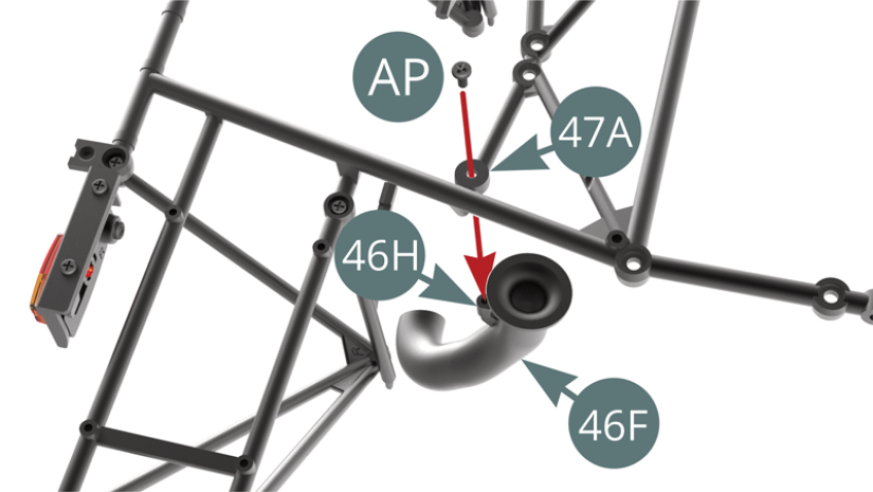
STEP 3
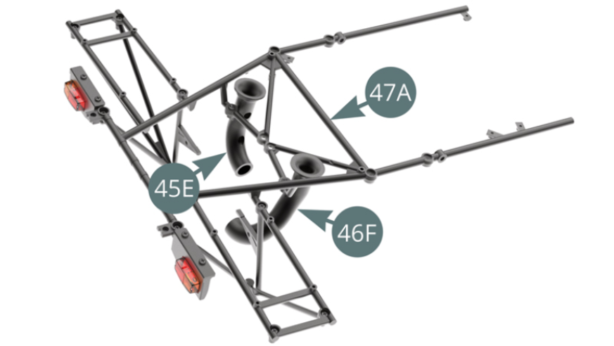
Position the transmission cooling line (46F) on the right side of the upper frame (47A) and secure it with an AP screw.
Position the transmission cooling line (45E) on the left side of the upper frame (47A) and secure with an AP screw.

STEP 4
The upper frame (47A) is ready to be installed on the main frame.
STEP 5
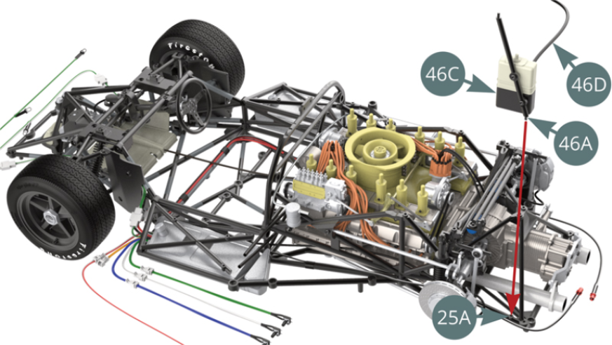
Position the engine oil recovery tank (46C) on the lower frame (25A) via the strut (46A).
STEP 6
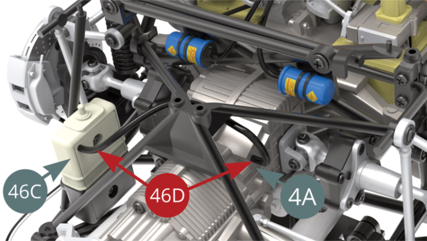
Position the engine oil recovery hose (46D) onto the nipple of the right gearbox housing (4A).
STEP 7
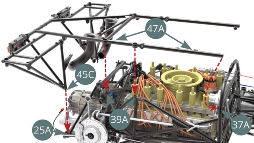
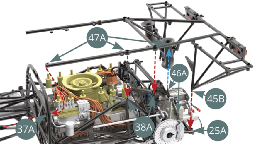
Align and position (by engaging the studs in the corresponding sockets as indicated by the red dotted arrows) the upper frame (47A) and the right-hand stand (45C) on the lower frame (25A), the right side frame (39A) and the cockpit partition frame (37A).
STEP 8
Align and position (by engaging the studs in the corresponding sockets as indicated by the red dotted arrows) the upper frame (47A) and the left-hand stand (45B) on the lower frame (25A), the left side frame (38A) and the cockpit partition frame (37A).
STEP 9
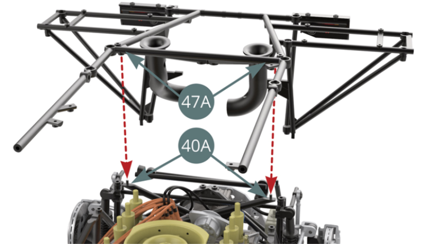
Align and position the upper frame (47A) - by engaging the pins in the corresponding sockets as indicated by the red dotted arrows - on the X-frame (40A).
STEP 10
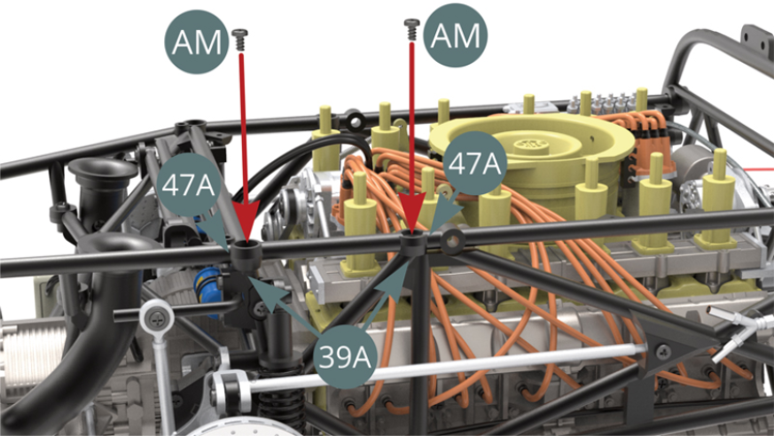
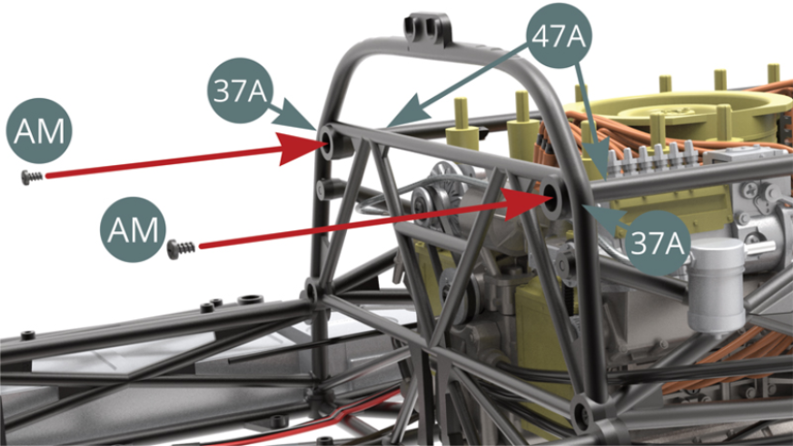
Attach the upper frame (47A) to the right side frame (39A) with two AM screws.
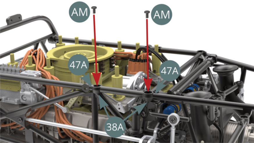
Fix the upper frame (47A) to the left side frame (38A) with two AM screws.
STEP 11
Attach the upper frame (47A) to the reinforcement frame (45A) with two AM screws.
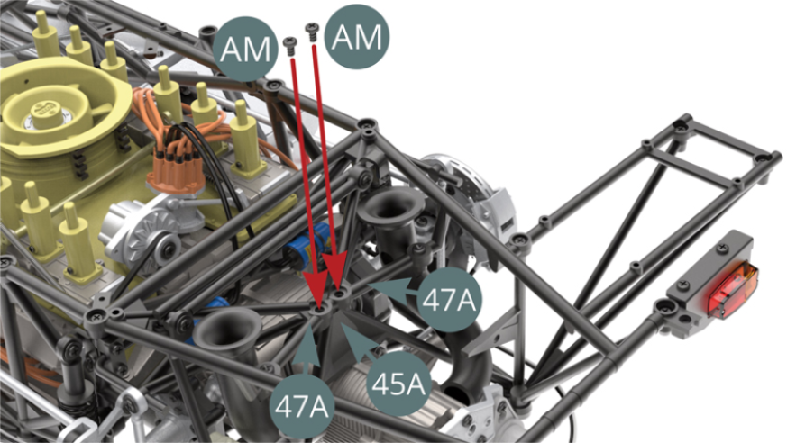
Secure the upper frame (47A) to the cockpit partition frame (37A) with two AM screws.
STEP 12
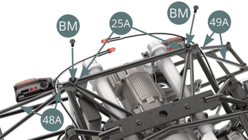
Attach the rear ends of the lower frame (25A) to the left (48A) and right (49A) tripod bars with two BM screws.
STEP 13
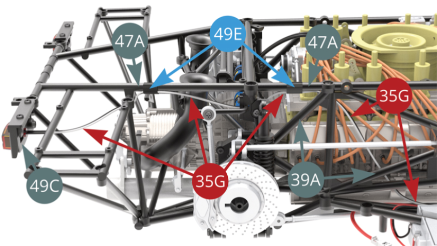
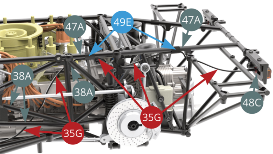
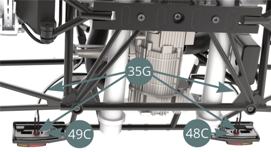
Run the tail light LED cable (35G) - black-white - behind the right side frame (39A), attach it to the top right bar of the upper frame (47A) with two adhesive tapes (49E), then engage the lamp in the right tail light reflector (49C).
STEP 14
Run the tail light LED cable (35G) - black-white - behind the left side frame (38A), attach it to the top left bar of the upper frame (47A) with two pieces of tape (49E), and then engage the lamp in the left tail light reflector (48C).
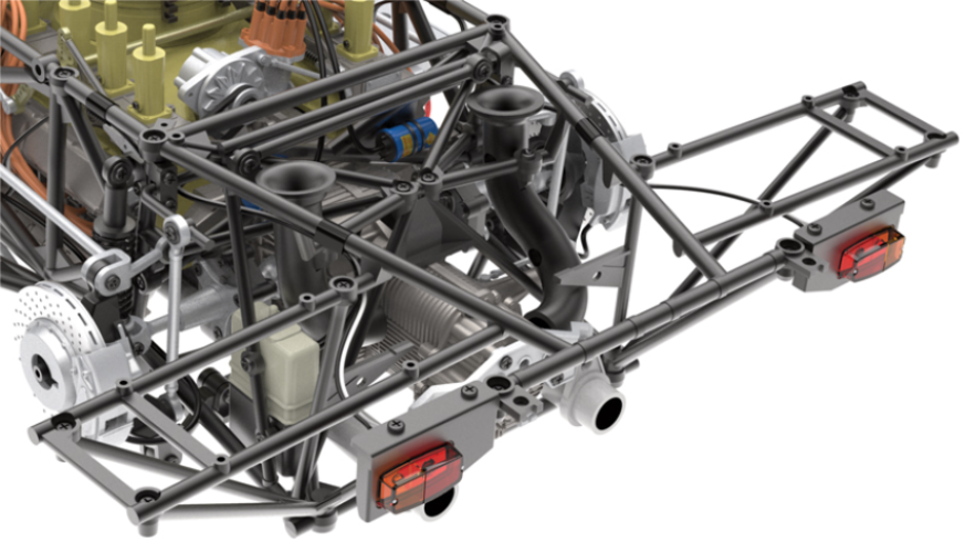
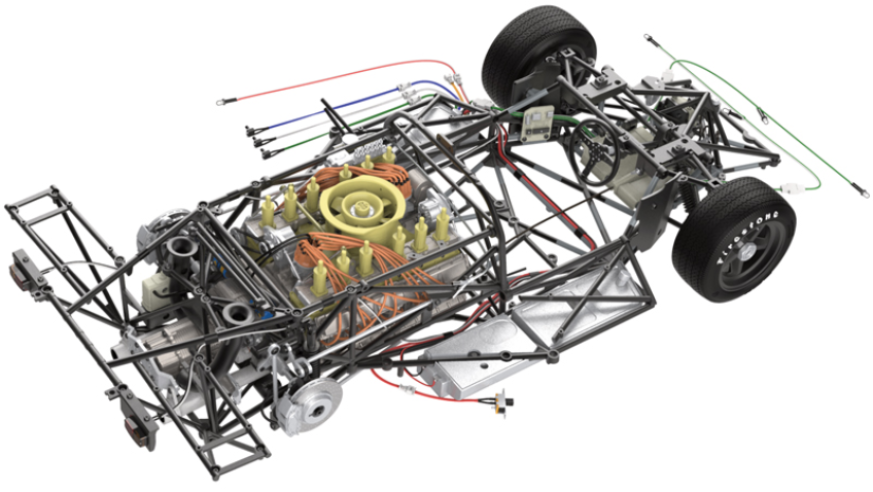
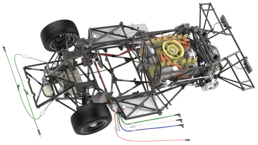
Installation of the upper frame on the main frame completed
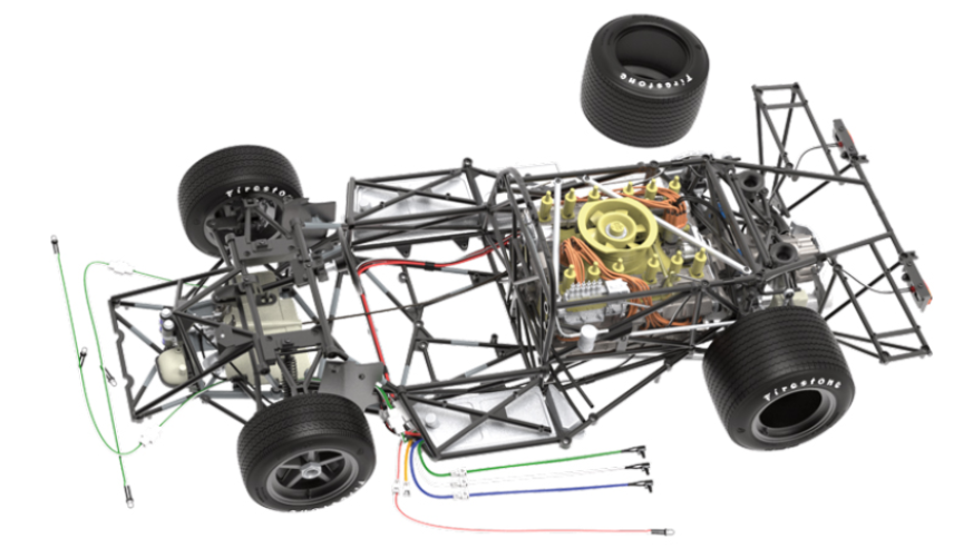
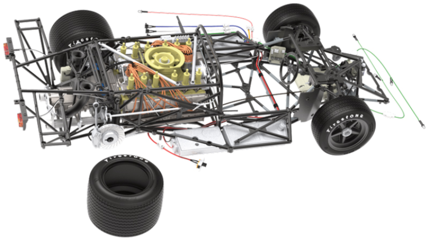
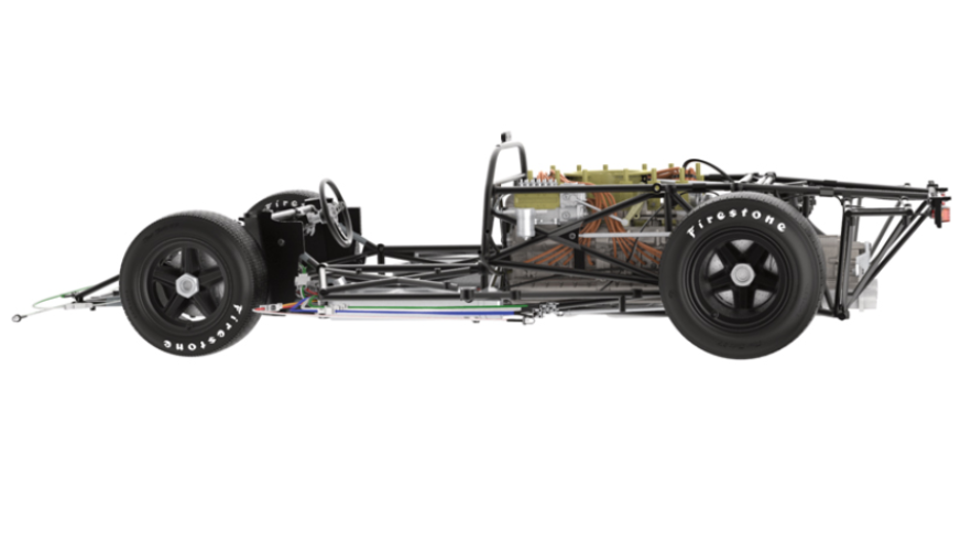
ASSEMBLY DIAGRAM

GENERAL VIEW
Kit 50
Parts of kit
- 50A Rear left tyre
- 50B Reinforcement bar
- IM Screw M 1.7 x 3.5 mm (x 3)
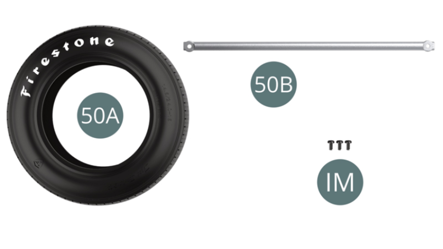
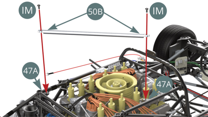
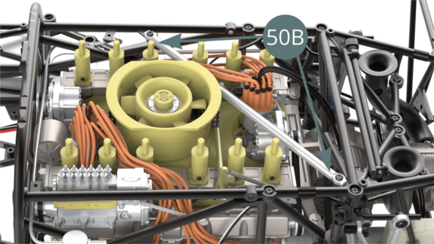
STEP 1
Position the reinforcement bar (50B) on the upper frame supports (47A) and secure it with two IM screws (shown opposite).
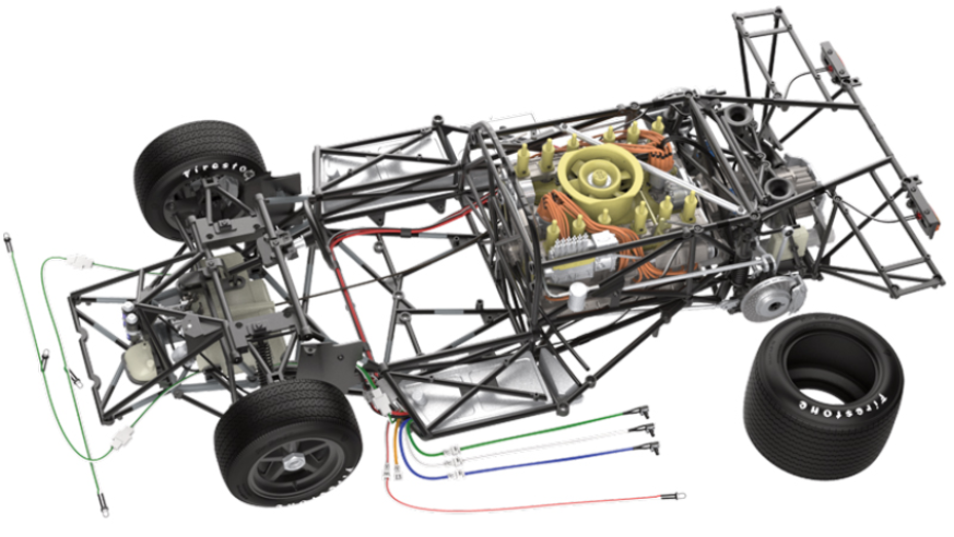
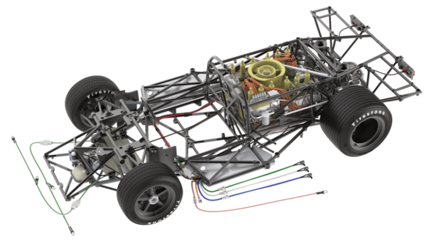
ASSEMBLY DIAGRAM
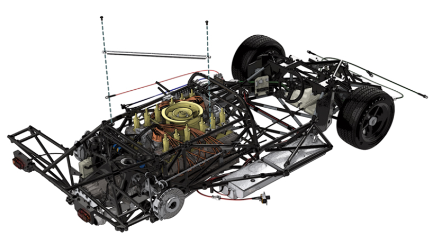
GENERAL VIEW

Kit 51
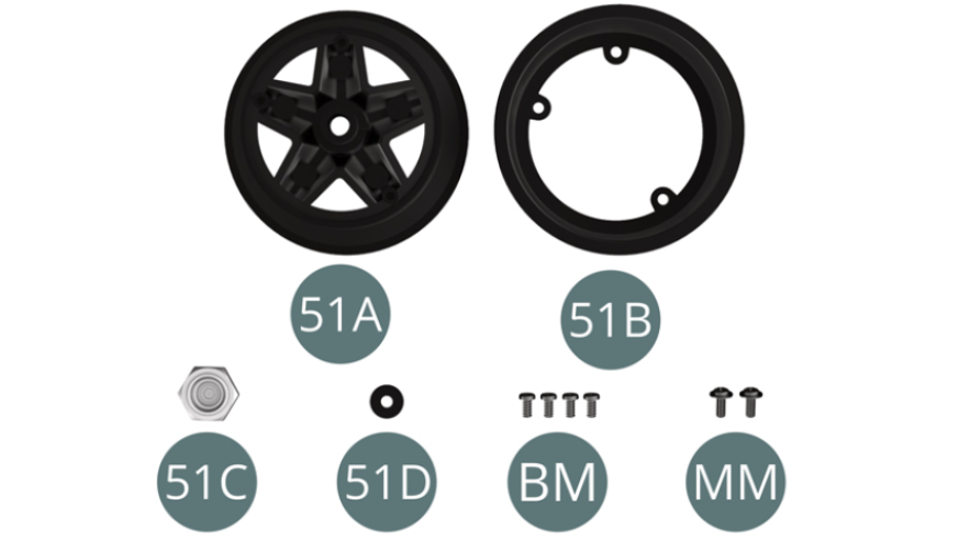
Parts of kit
- 51A Rear wheel outer rim
- 51B Rear wheel inner rim
- 51C Hub cover
- 51D Washer
- BM Screw M 2 x 4 mm (x 4)
- MM Screw M 2 x 5 x 5mm (x 2)
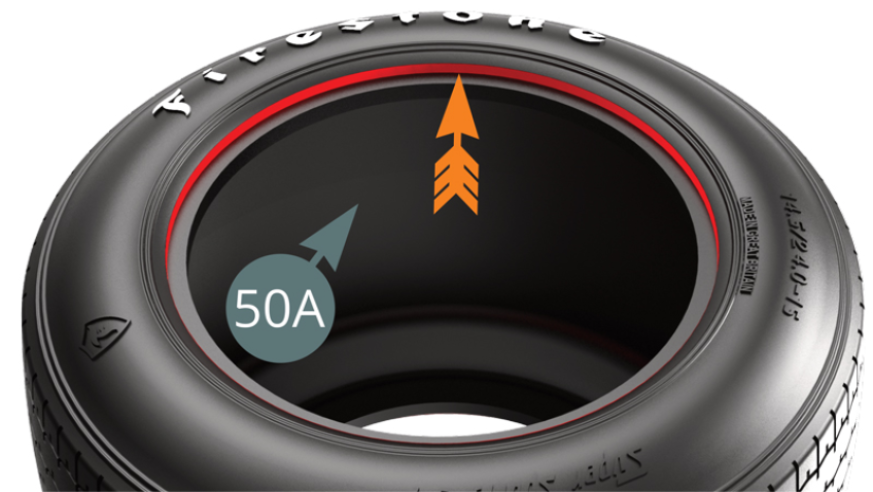
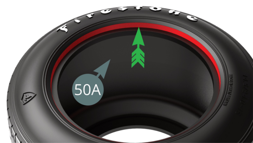
STEP 1
Before starting the assembly of the left rear wheel, locate the side of the tyre (50A) with the deepest bead by the red markings in order to position the outer rim (51A). The deepest bead (2 mm) is indicated by the green arrow, while the shallowest (1 mm) is indicated by the orange arrow.
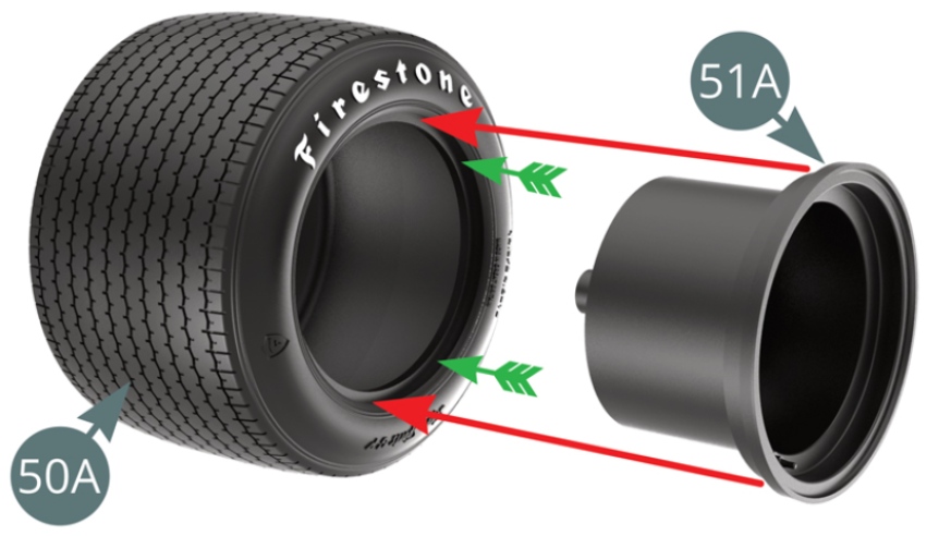
STEP 2
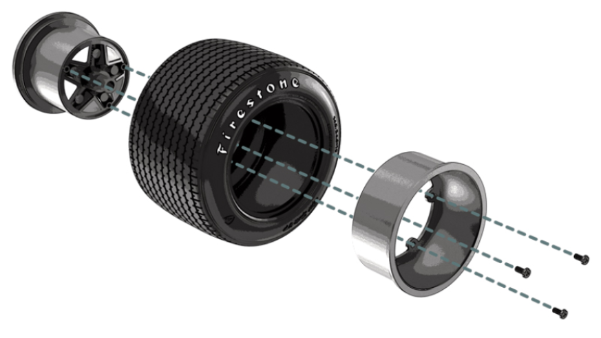
To fit the tyre (50A) - on the side with the deepest bead, green arrows - to the outer rim (51A), plunge it into hot water for two minutes so that the rubber becomes more flexible.
Position the inner rim (51B) on the other side of the tyre, aligning the three fixing points correctly.
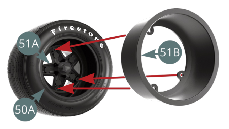
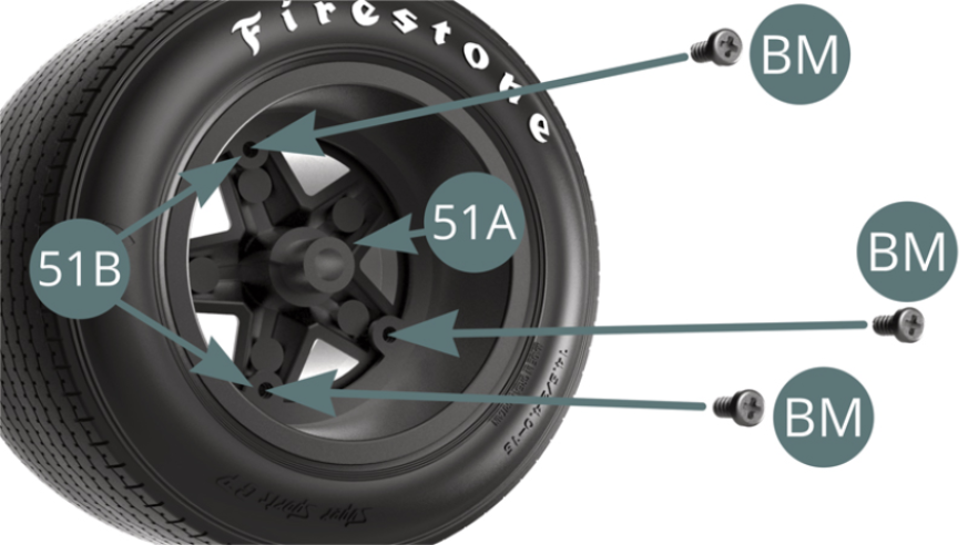
STEP 3
Fix the inner rim (51B) and the outer rim (51A) together with three BM screws. The left rear wheel is ready to be mounted on the chassis.
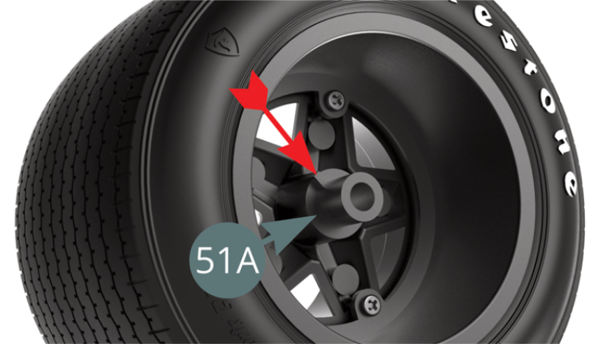
STEP 4
Identify the locking groove on the outer rim hub axle (51A) - red arrow.
Position the outer rim of the left rear wheel (51A) on the left rear pin (41A) and rotate the wheel (blue arrow) until the locking groove engages the slot in the outer brake half disc (44G).
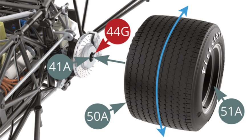
STEP 5
Fix the outer rim of the left rear wheel (51A) with a MM screw by first passing it through the washer (51D).
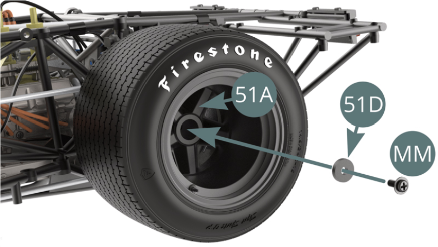
Position the hub cover (51C) on the outer rim (51A).
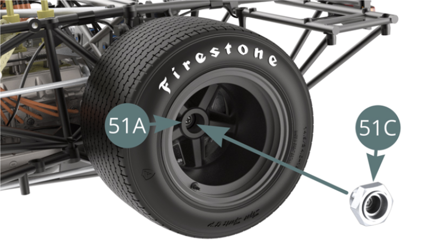
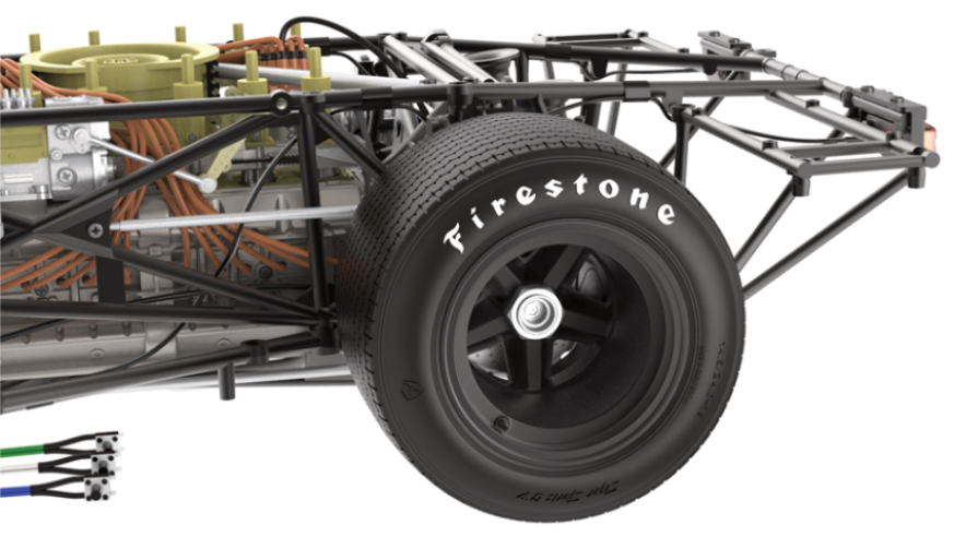
Left rear wheel 51A installed on the frame
ASSEMBLY DIAGRAM

GENERAL VIEW
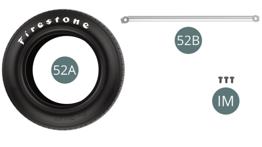
Kit 52
Parts of kit
- 52A Rear left tyre
- 52B Reinforcement bar
- IM Screw M 1.7 x 3.5 mm (x 3)
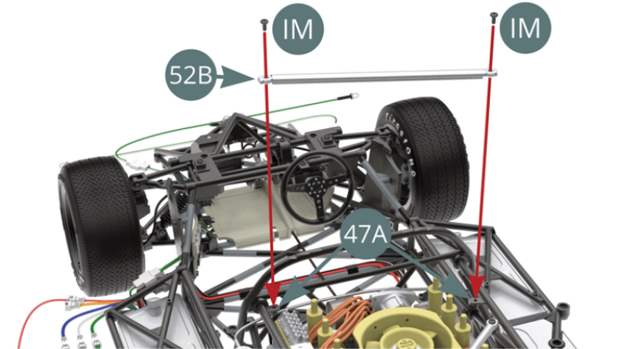
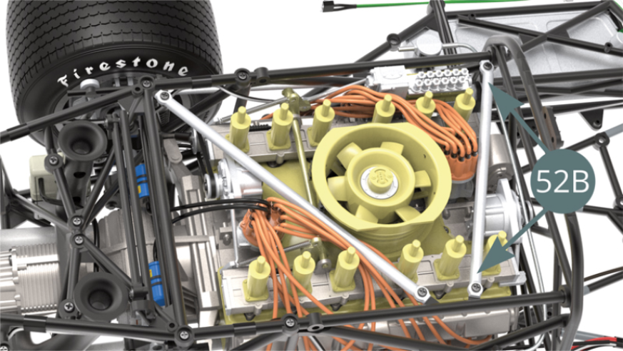
STEP 1
Position the reinforcement bar (52B) on the upper frame supports (47A) and secure it with two IM screws (shown opposite).
ASSEMBLY DIAGRAM

GENERAL VIEW