English
 français
 Deutsch
 español
 italiano
 português


Box 16
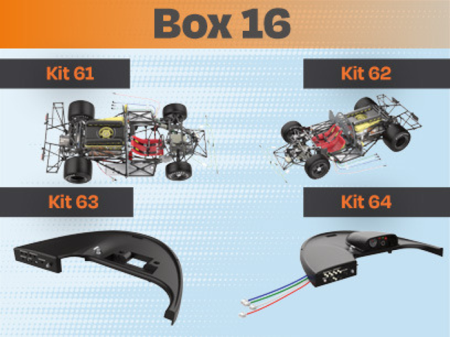
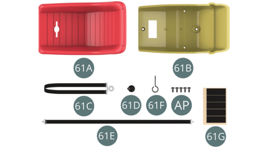
Kit 61
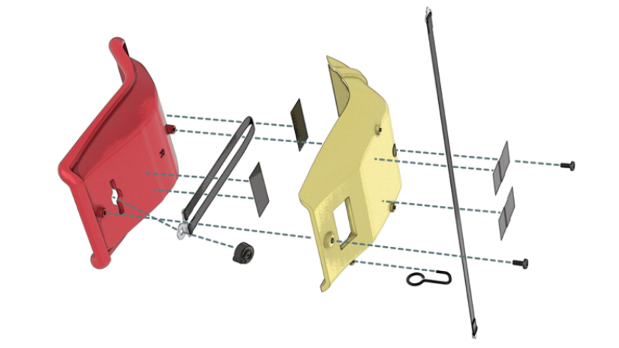
Parts of kit
- 61A Driver's seat upholstery
- 61B Driver's seat
- 61C Lower safety belt
- 61D Buckle lock
- 61E Upper safety belt
- 61F Seat adjustment lever
- 61G Adhesive tape ( x5 )
- AP screw M 1.7 x 4 mm screw (x 5)
Step 1
Pass the lower safety belt (61C) through the slot in the driver's seat upholstery (61A) and fit the lock (61D) in its buckle.
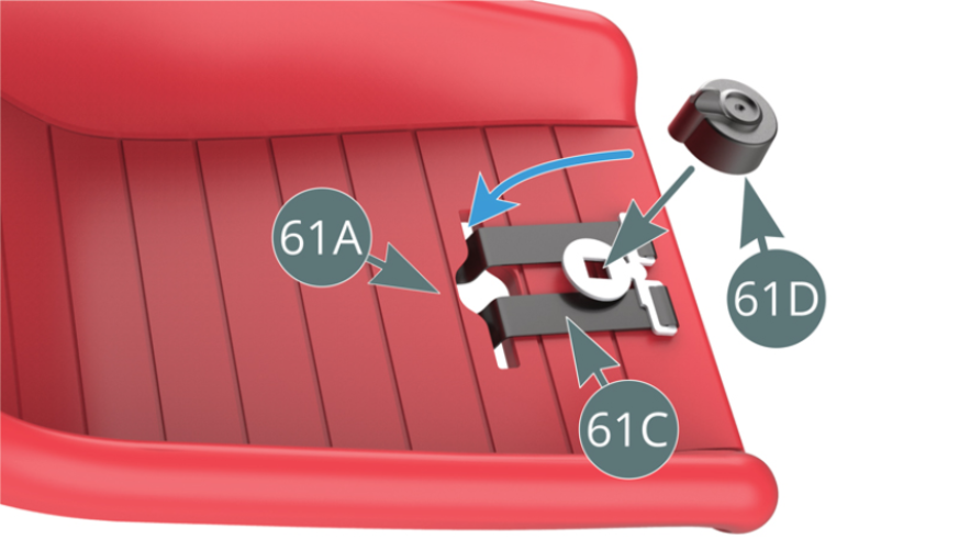
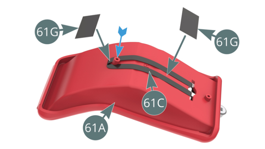
Route the opposite end of the lower safety belt (61C) around the pin on the driver's seat upholstery (61A) - blue arrow - and secure with two strips of tape (61G).
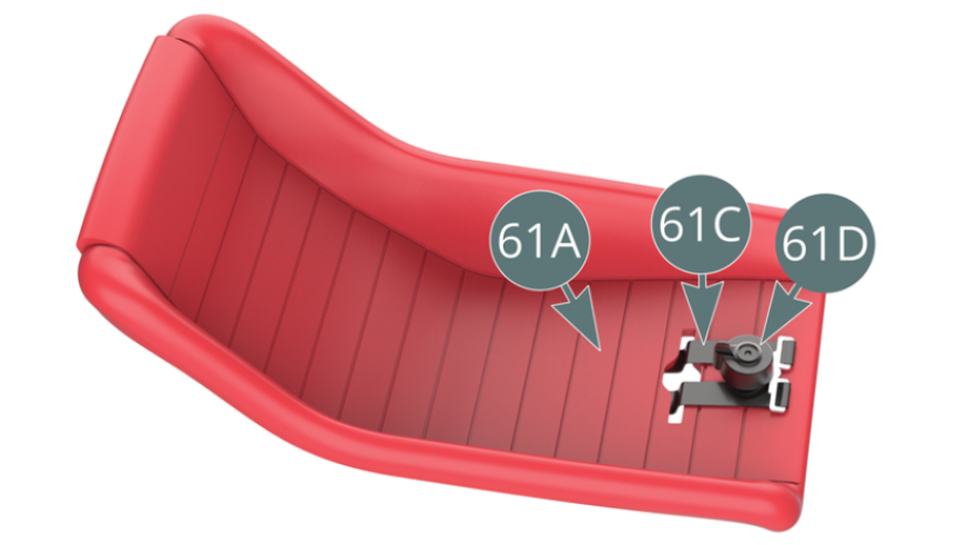
Step 2
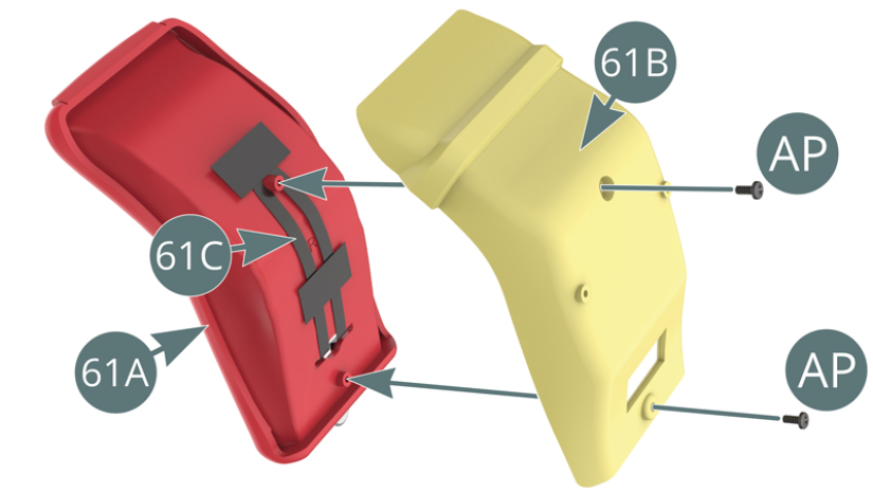
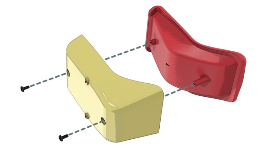
Lower safety belt (61C) with buckle lock (61D) attached to the driver's seat upholstery (61A).
Place the driver's seat upholstery (61A) on the driver's seat (61B) and secure with two AP screws.
Step 3
Position the midpoint of the upper safety belt (61E) halfway across the base of the driver's seat (61B) - red arrow - and secure with two pieces of tape (61G).
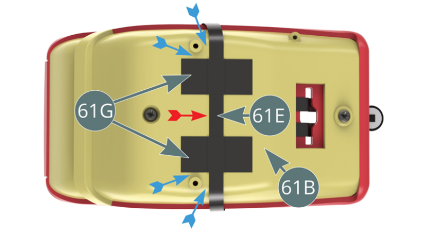
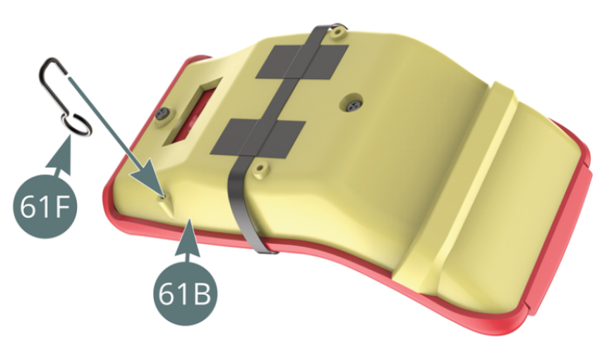
Ensure the tapes are a minimum of 2 mm from the mounting holes (blue arrows). Fit the seat adjustment lever (61F) to the base of the driver's seat (61B).
Step 4
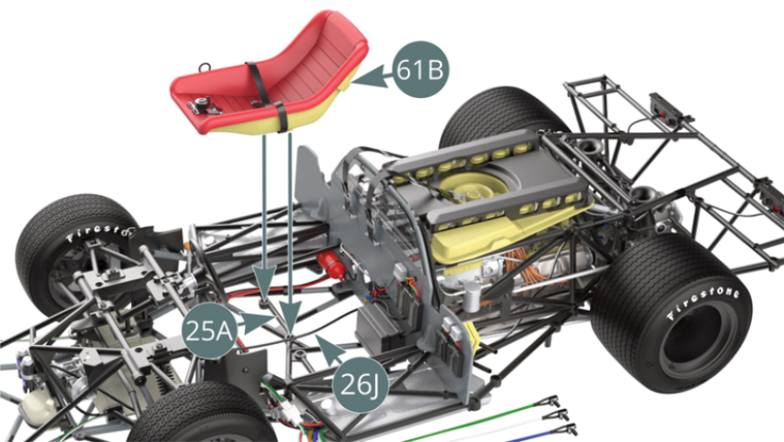
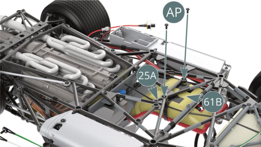
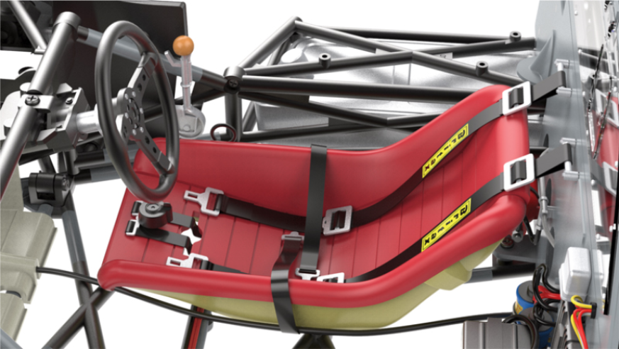
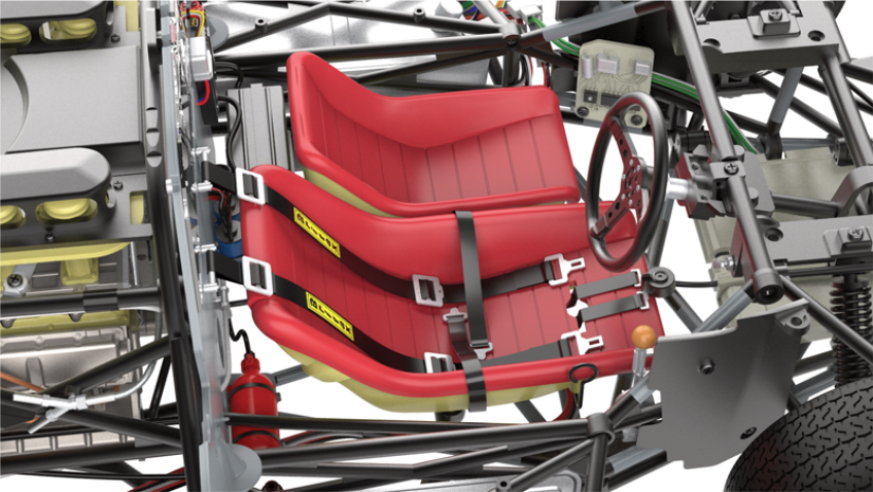
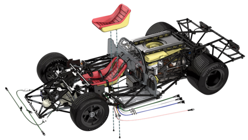
Move the clutch cable (26J) slightly to the left side and mount the driver's seat (61B) on the lower chassis (25A). Secure the driver's seat (61B) to the lower chassis (25A) with two AP screws.
Step 5
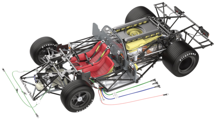
The driver's seat is installed on the chassis.
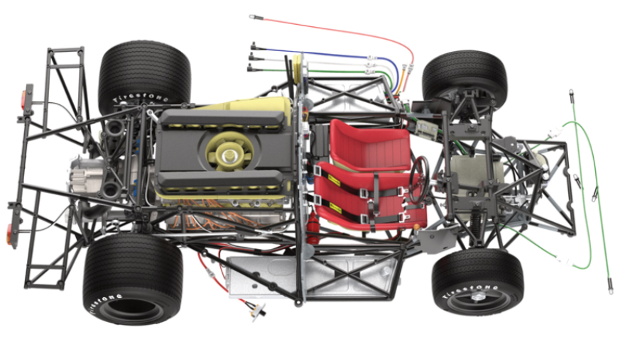
ASSEMBLY DIAGRAM

GENERAL VIEW
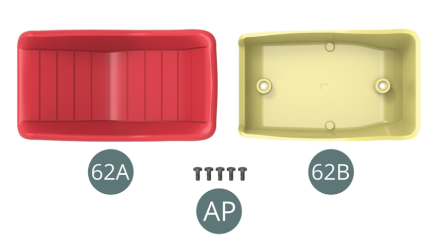
Kit 62
Parts of kit
- 62A Passenger seat upholstery
- 62B Passenger seat
- AP Screw M 1.7 x 4 mm (x 5)
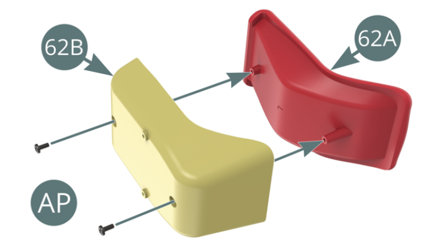
Step 1
Mount the passenger seat upholstery (62A) to the passenger seat (62B) and secure with two AP screws.
Position the passenger seat (62B) on the lower chassis (25A).
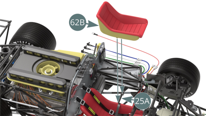
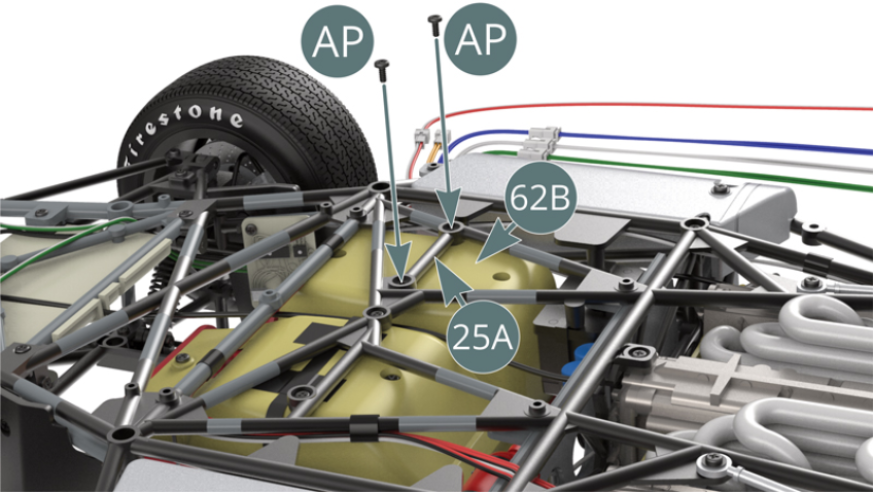
Step 2
Secure the passenger seat (62B) to the lower chassis (25A) with two AP screws.
Step 3
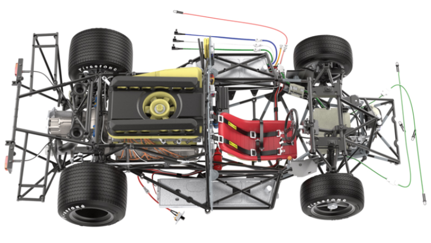
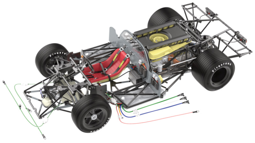
The driver and passenger seats are fastened to the chassis.
ASSEMBLY DIAGRAM
GENERAL VIEW
Kit 63
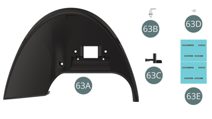
Parts of kit
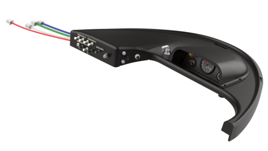
- 63A Dashboard
- 63B Lever
- 63C Starter switch
- 63D Ignition key
- 63E Dashboard decal ( x2 )
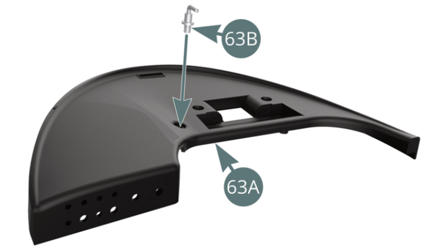
Step 1
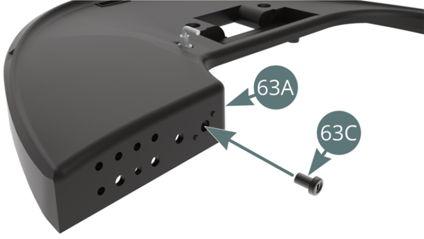
Fit the lever (63B) to the dashboard (63A). Detach the starter switch (63C) from its support.
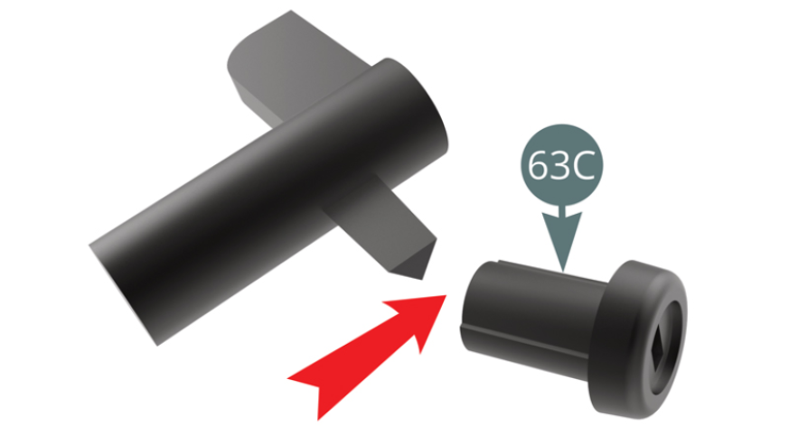
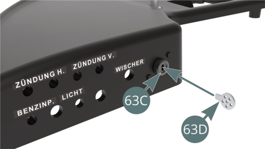
Step 2
Install the starter switch (63C) on the dashboard (63A).
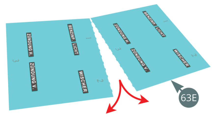
Separate two sets of the dashboard decals (63E) and start using one of them.
Step 3
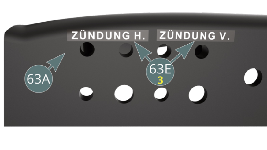
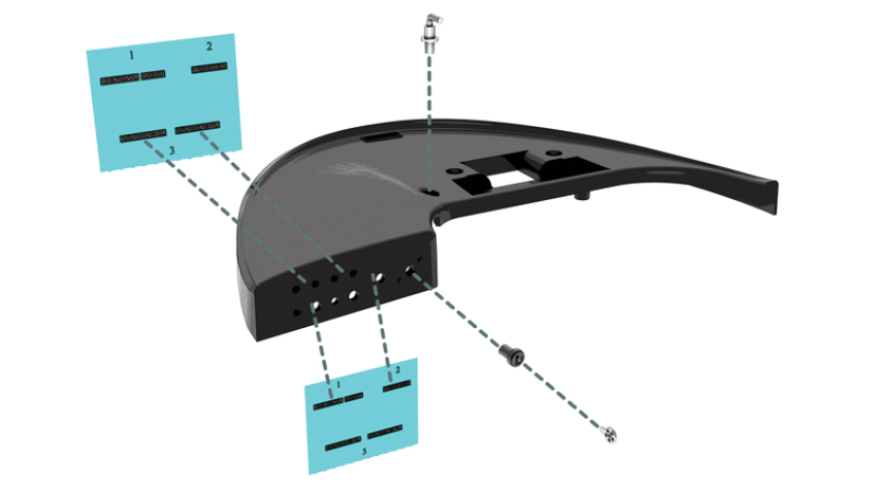
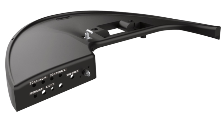
Dip the decals (63E-3) in water for 15 seconds and then peel off the decals and apply them to the dashboard (63A) as shown.
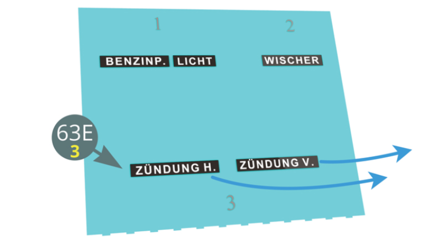
Decals (63E-3) "On tail lights" ( Zundung H ) and "On headlights" ( Zundung V ) to be applied to the dashboard (63A).
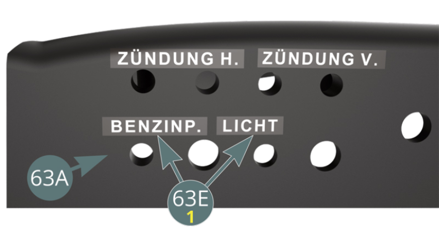
Step 4
Dip decals (63E-1) in water for 15 seconds and then peel off the decals and apply them to the dashboard (63A) as shown.

Fuel pump" ( Benzin P. ) and "Light" ( Licht ) decals to be applied to the dashboard (63A).
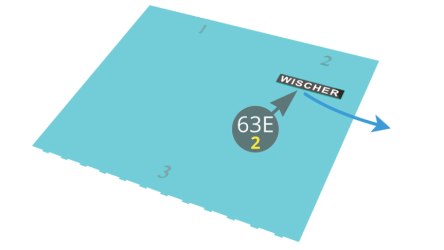
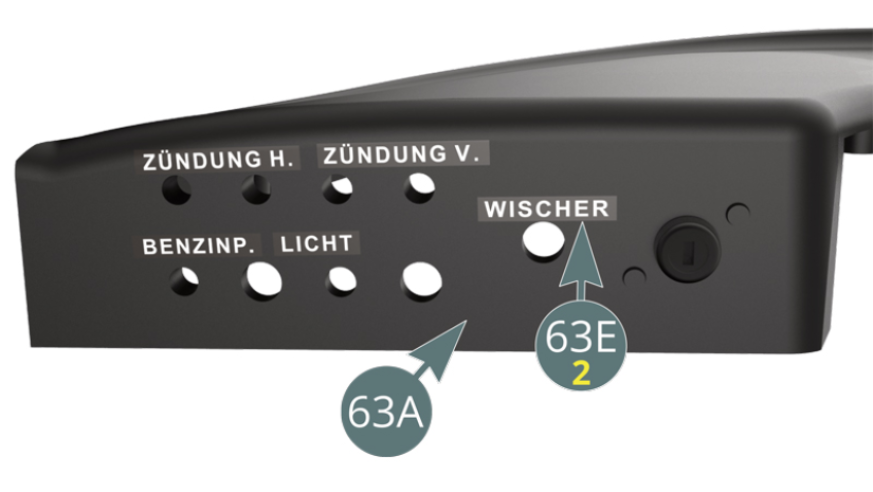
Step 5
Dip decal (63-E-2) in water for 15 seconds, peel off decal and apply to dashboard (63A) as shown below.
The decal "Windscreen Wiper" ( Wischer ) (63E-2) to be applied on the dashboard (63A).
Step 6
Insert the ignition key (63D) into the starter switch (63C).
ASSEMBLY DIAGRAM
GENERAL VIEW
Kit 64
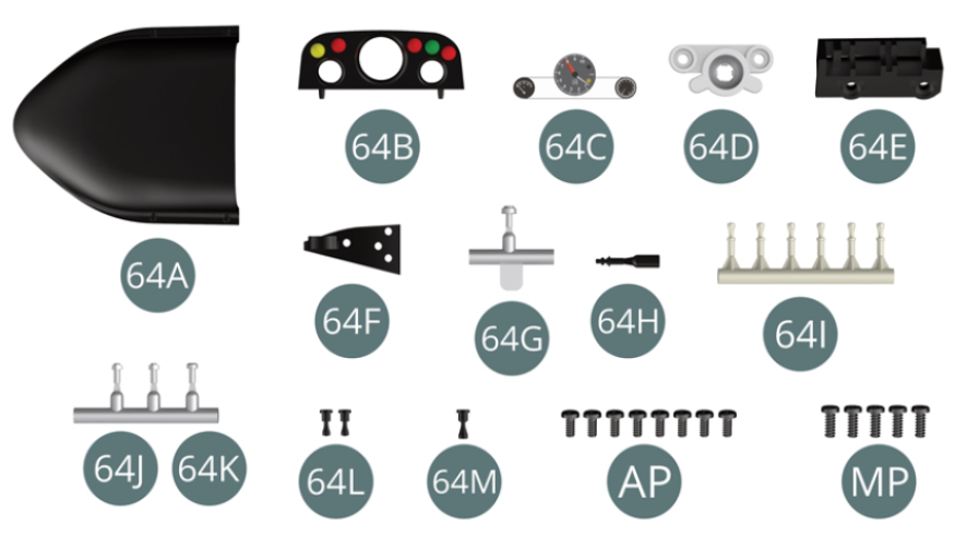
Parts of kit
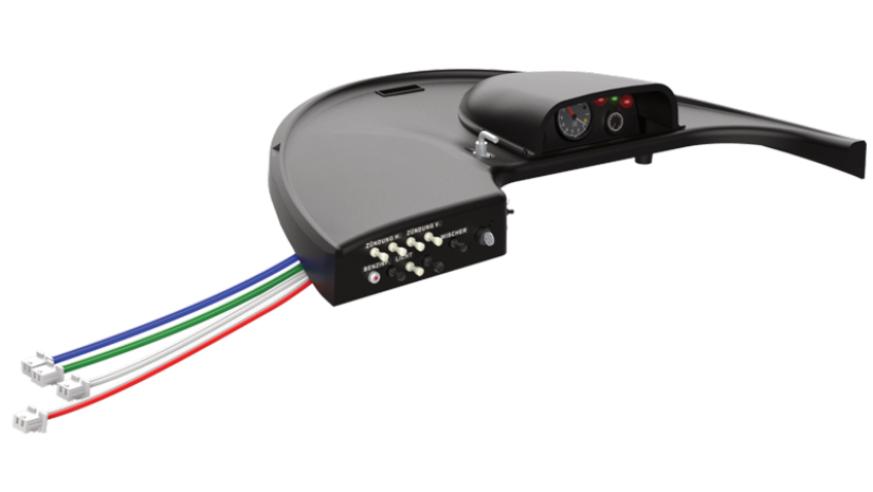
- 64A Instrument panel cover
- 64B Instrument panel
- 64C Dials
- 64D Reflector panel
- 64E Switch panel
- 64F Switch panel
- 64G Interrupters
- 64H Interrupters
- 64I Interrupters (x 6)
- 64J Interrupters (x 2)
- 64K Fuel pump contactor
- 64L Switch (x 2)
- 64M Switch
- AP screw M 1,7 x4mm ( x8 )
- MP screw M 2,0 x5mm ( x5 )
Step 1
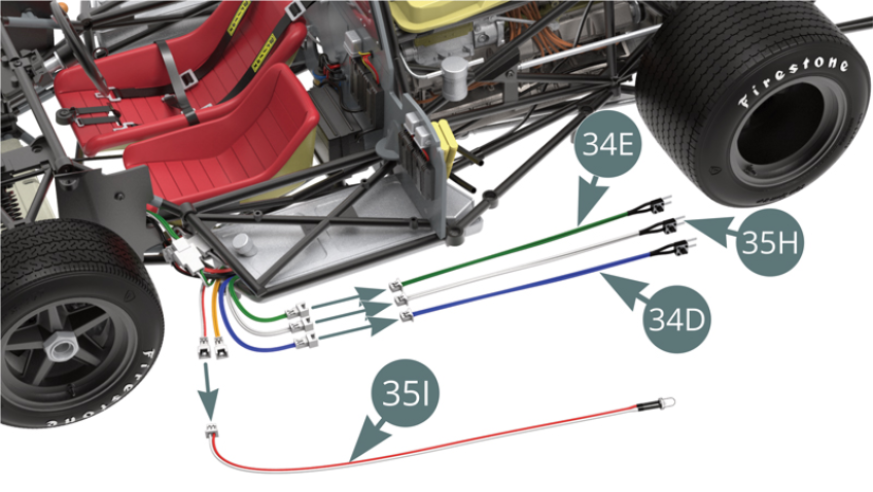
Disconnect the cable from the horn sound switch (34E / green), the cable from the light switch (35H / white), the cable from the engine sound switch (34D / blue) and the cable from the instrument light LED (35I / red-white).
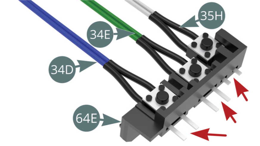
Insert the contact legs of the horn sound switch (34E / green), the light switch (35H / white) and the engine sound switch (34D / blue) into the corresponding slots in the switch panel (64E) (red arrows).
Step 2
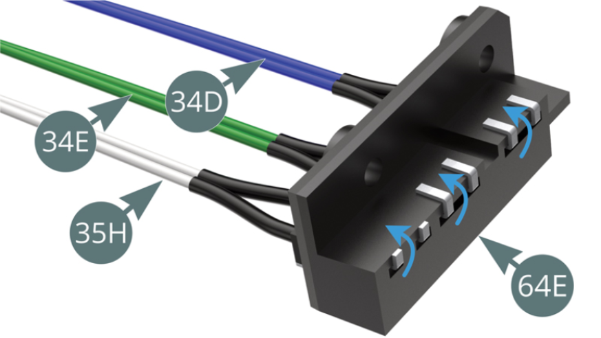
Bend the contact legs of the cables belonging to the horn switch (34E / green), light switch (35H / white) and engine sound switch (34D / blue) over the top edge of the switch panel (64E) - (blue arrows).
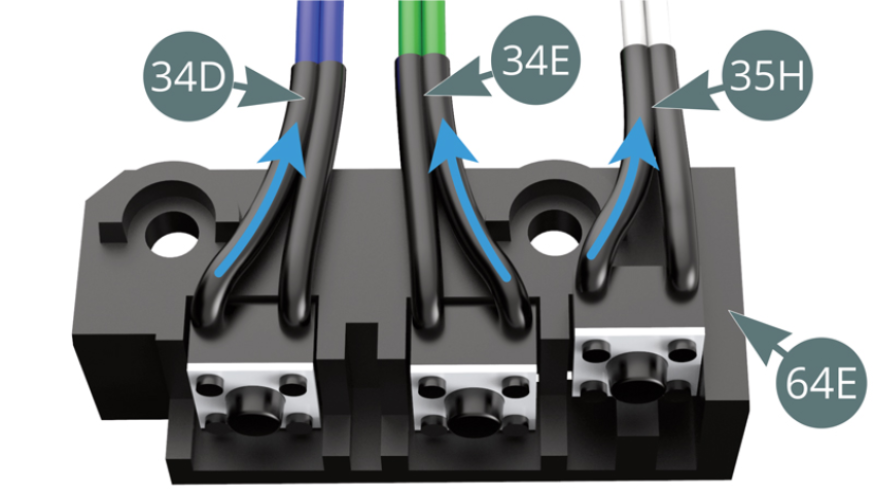
Bend the black ends of the cables of the horn switch (34E / green), light switch (35H / white) and engine sound switch (34D / blue) to fit around the two fixing holes in the switch panel (64E) - (blue arrows).
Step 3
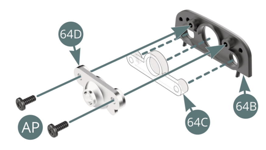
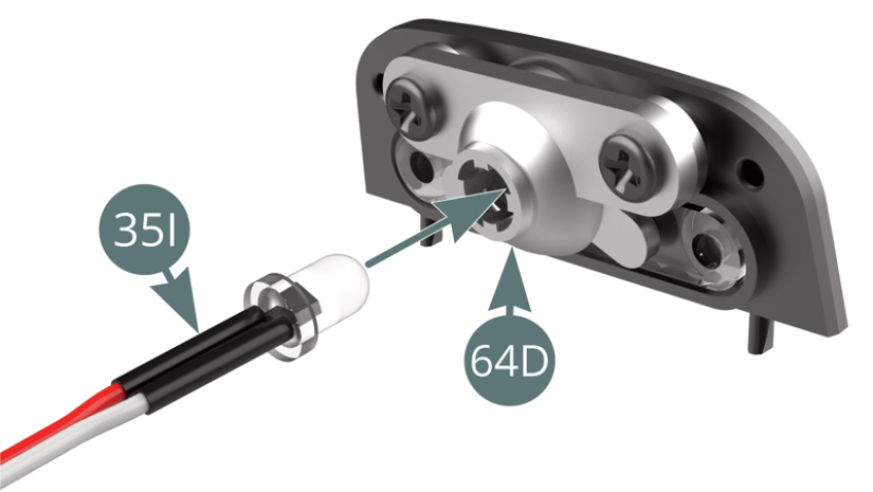
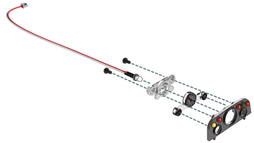
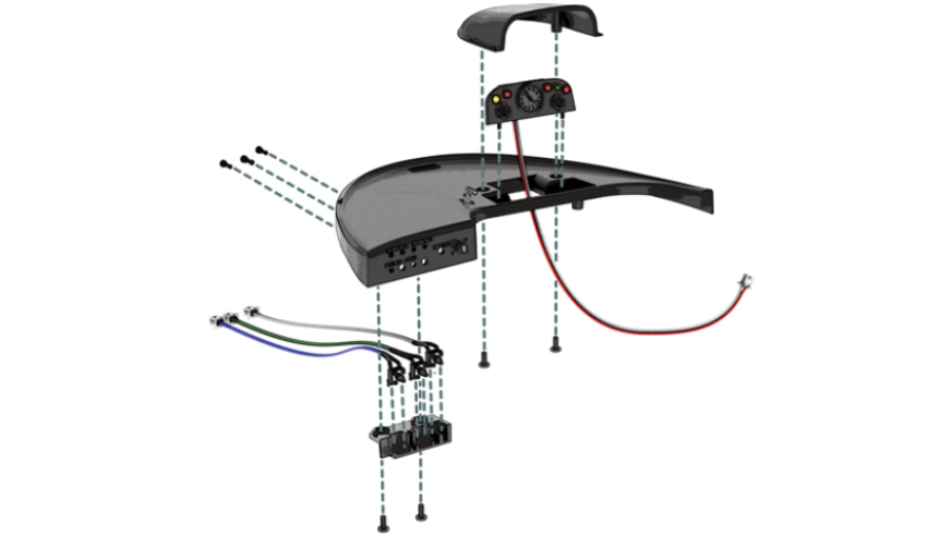
Position the reflector panel (64D) on the instrument panel (64B), with the dial block (64C) in the middle and fix with two AP screws. Mount the instrument LED light (35I) on the reflector panel (64D).
Step 4
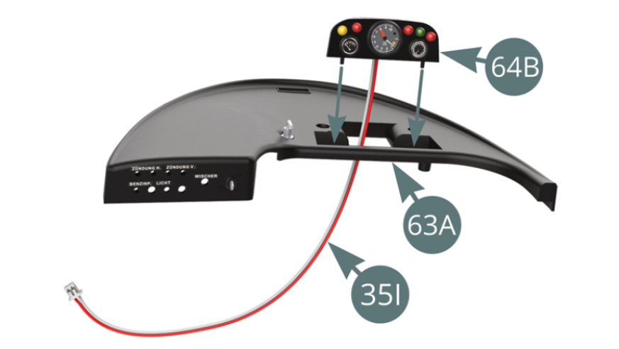
Position the instrument panel (64B) on the dashboard (63A) by passing the instrument backlight LED cable (35I) through the opening provided.
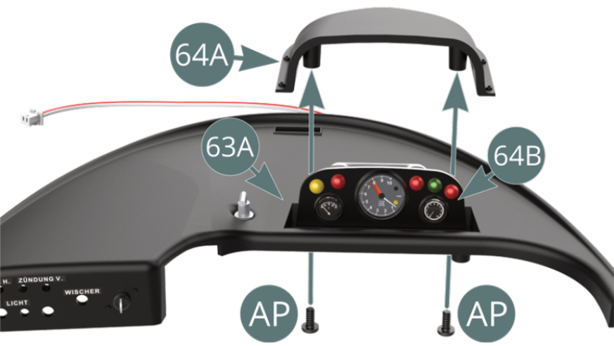
Position the instrument panel cover (64A) over the instrument panel (64B) and onto dashboard (63A) and secure it from below with two screws A.
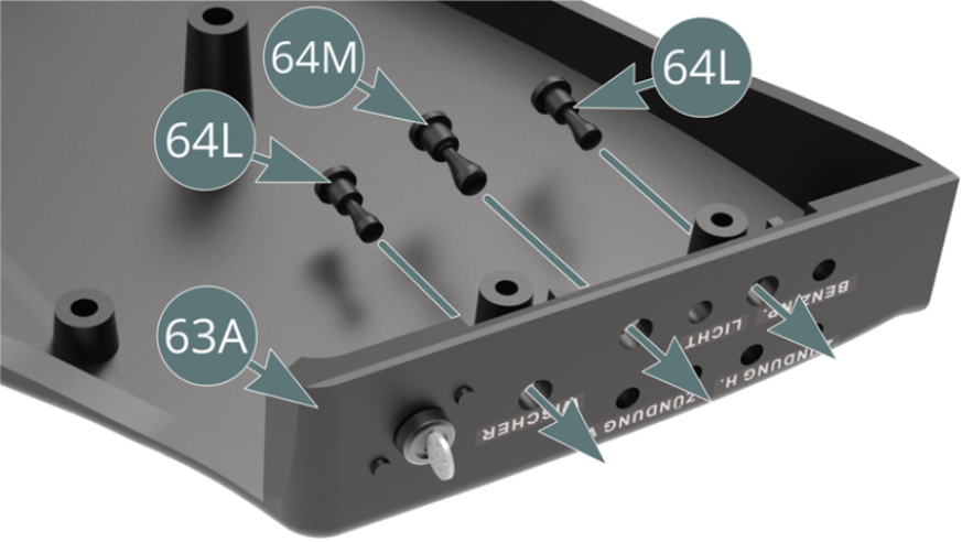
Step 5
Position switches (64L & 64M) on the instrument panel (63A) as shown below.
Position the switch panel (64E) on the instrument panel (63A), ensuring that the contactors can be pressed with their respective switches(64L & 64M).
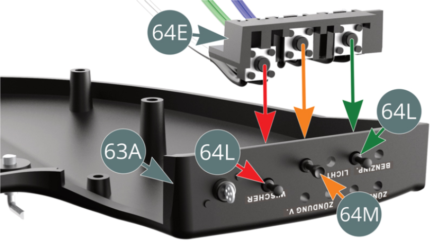
Step 6
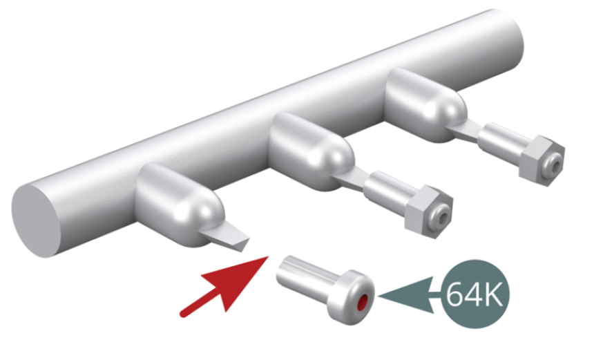
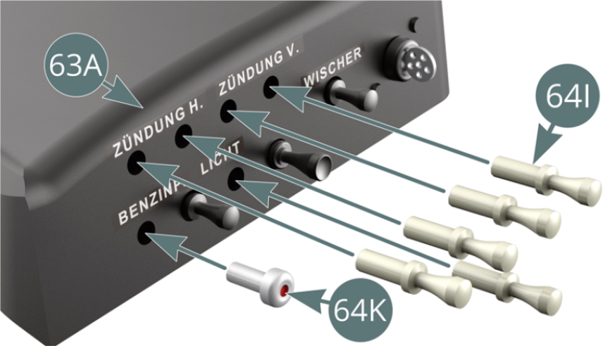
Secure the switch panel (64E) to the dashboard (63A) with two AP screws. Detach the fuel pump contactor (64K) from its sprue.

Step 7
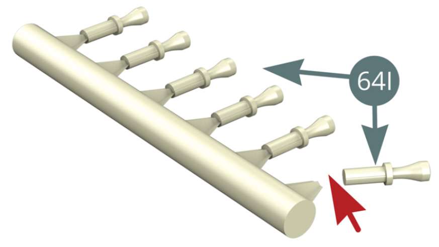
Detach five interrupters (64I) from the sprue.
Step 8
Install the fuel pump contactor (64K) and the five interrupters (64I) on the dashboard (63A).
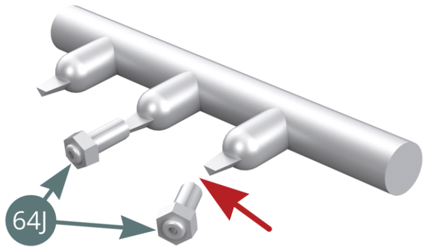
Step 9
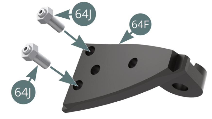
Detach two interrupters (64J) from the sprue. Install the two interrupters (64J) into the switch panel (64F).
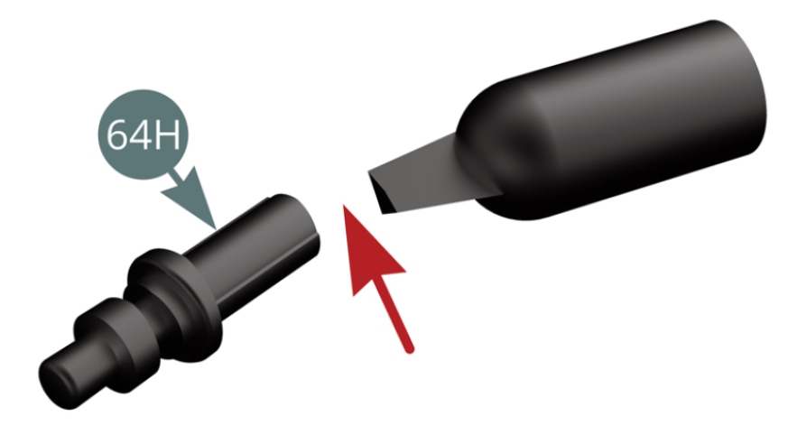
Step 10
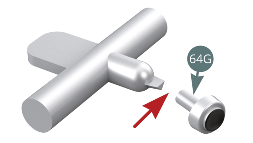
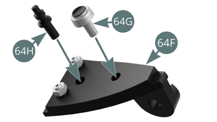
Detach the Interrupters (64H & 64G) from the sprue. Install the Interrupters (64H & 64G) into the switch panel (64F).
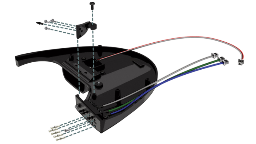
Step 11
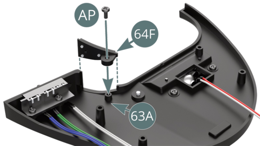
Mount the switch panel (64F) on the dashboard (63A) and secure with an AP screw. Bundle the blue, green, white and red-white cables and route them towards the left-hand side of the dashboard (63A).

ASSEMBLY DIAGRAM
GENERAL VIEW