English
 français
 Deutsch
 español
 italiano
 português


Box 17
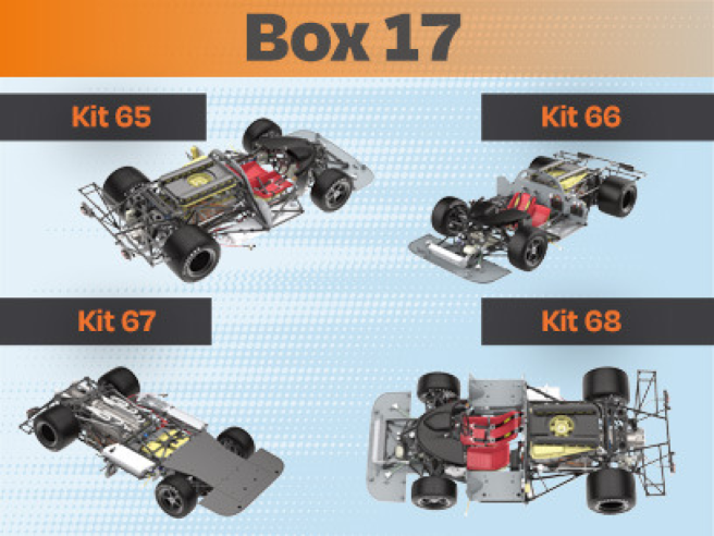
Kit 65
Parts of kit
- 65A Flat front floor
- PM Screw M 2,0 x 4 mm (x 5)

Step 1
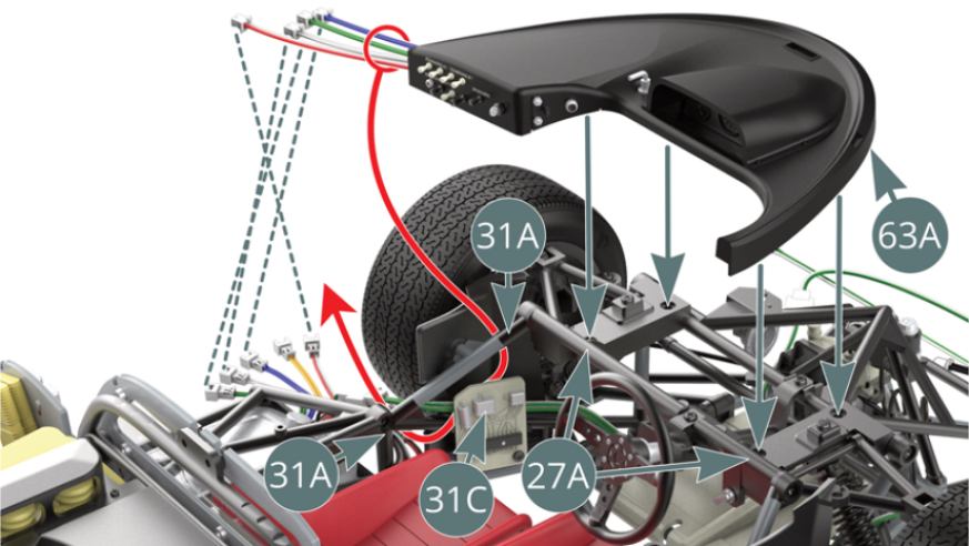
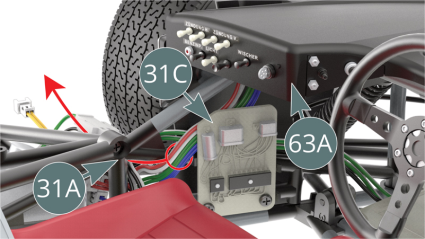
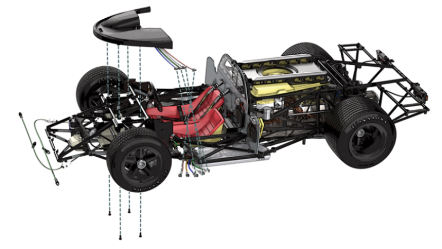
Before installing the dashboard (63A) onto the dashboard frame (27A), route the four dashboard cables (blue, green, white and red-white) between the frame (31A) and the connection panel (31C) as indicated by the red arrow (illustrations below).
Etape 2
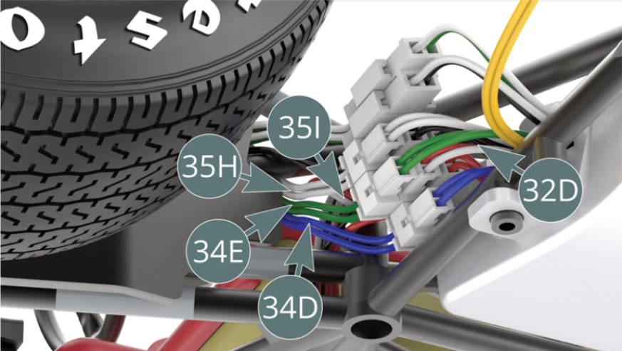
Connect the wires (35I - red-white), (35H - white), (34E - green) and (34D - blue) from the dashboard to the four wires of the corresponding colour from the PCB (32D) . At present, only the yellow wire is not connected.
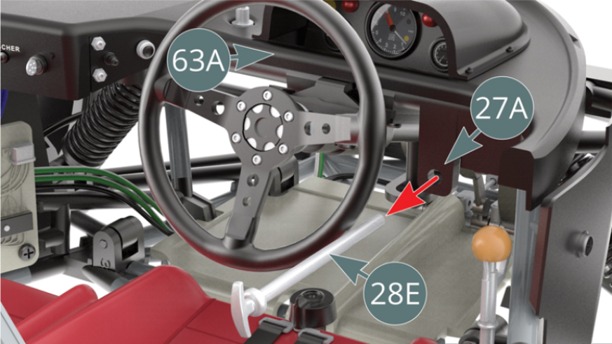
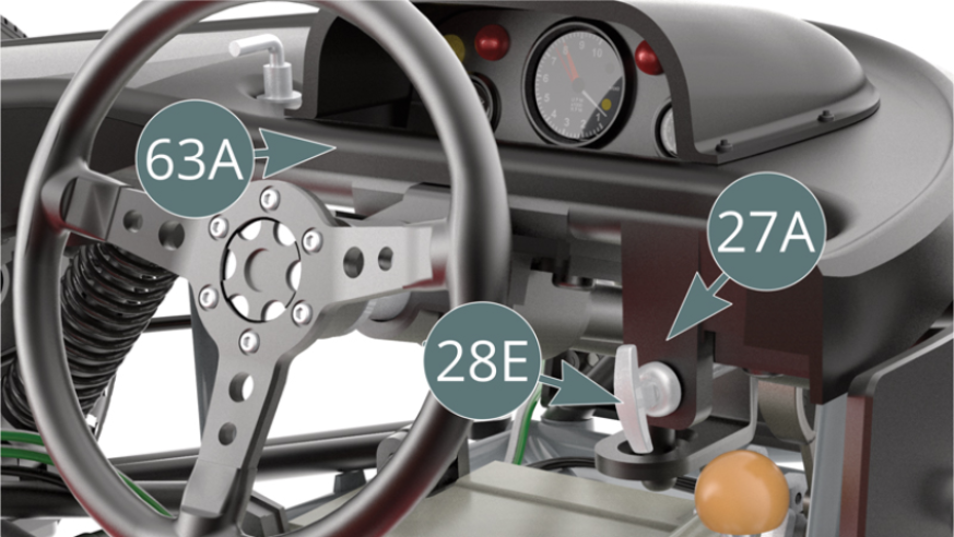
With the dashboard (63A) positioned on the dashboard frame (27A), remove (temporarily) the fire extinguisher pull tab (28E).
Etape 3
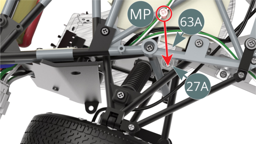
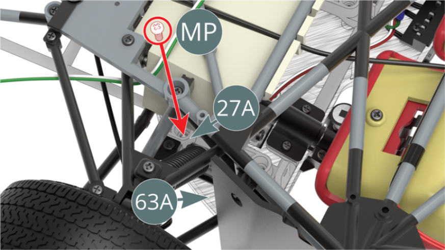
Attach the dashboard (63A) to the dashboard frame (27A) from underneath the car with two MP screws. Attach the instrument panel (63A) to the instrument panel frame (27A) - at the front left wheel - with a PM screw.

Etape 4
Attach the dashboard (63A) to the dashboard frame (27A) at the right front wheel with an MP screw. Replace the fire extinguisher pull tab (28E) on the dash frame (27A).
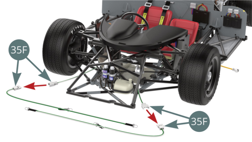
Etape 5
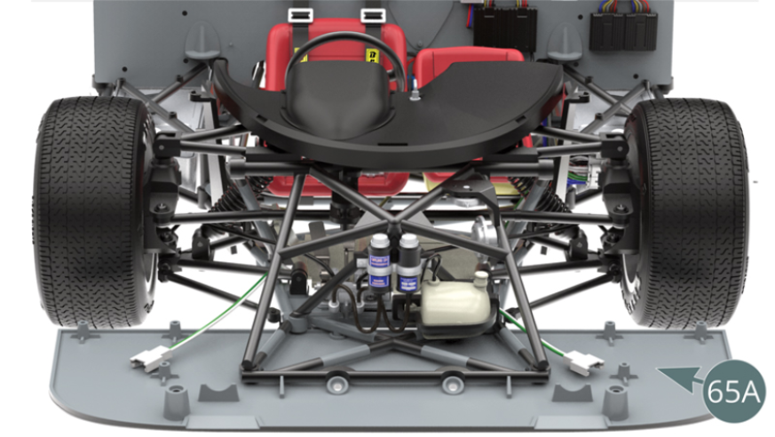
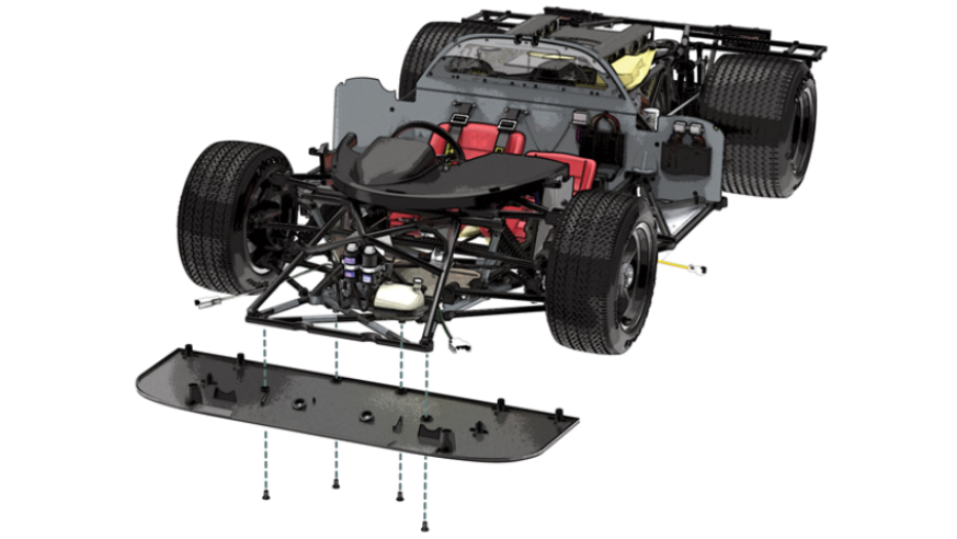
Disconnect the headlight LED cables (35F) on the right and left. Put them aside for future use. Position the front flat bottom (65A) onto the lower frame (25A) and secure with four PM screws.
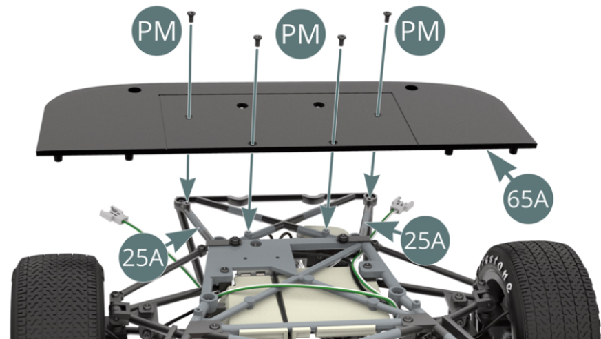
Etape 6
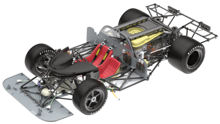
The front flat base (65A) is installed on the chassis.
ASSEMBLY DIAGRAM
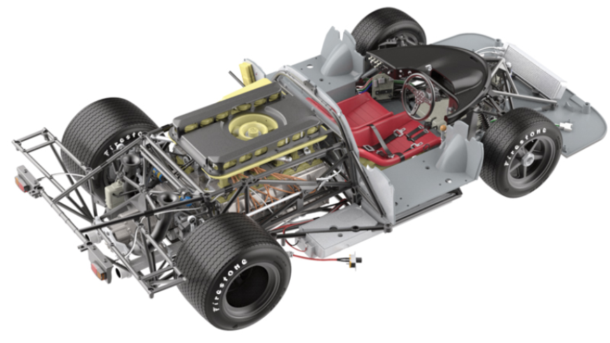
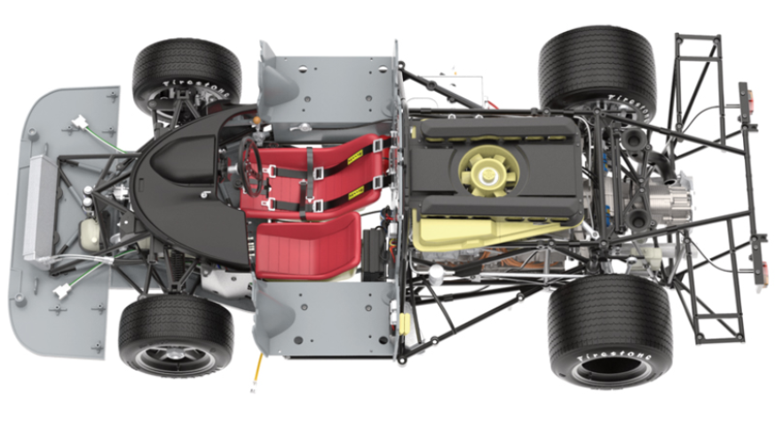
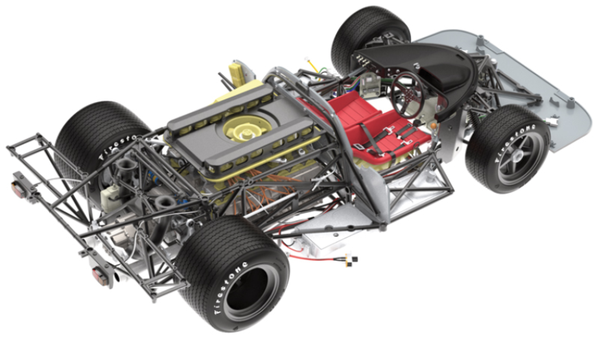
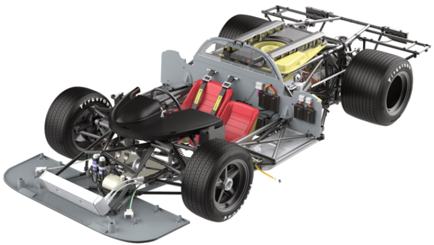
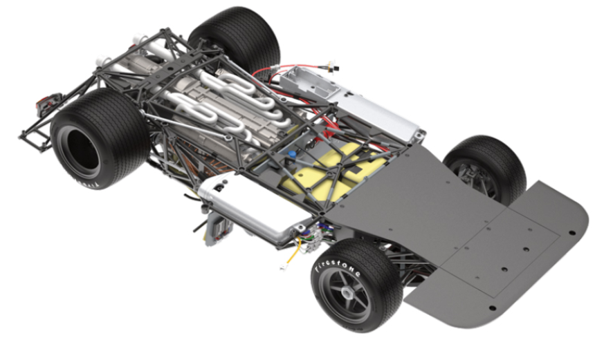
GENERAL VIEW
Kit 66
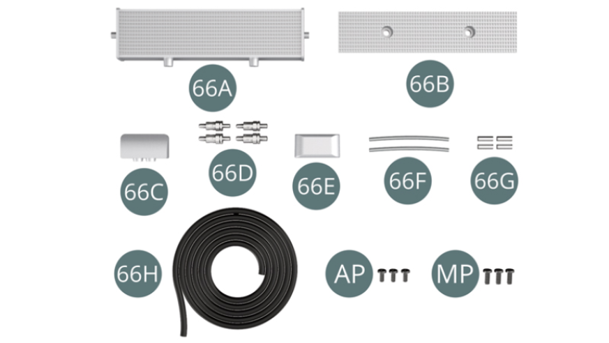
Parts of kit
- 66A Water radiator
- 66B Radiator front panel
- 66C Radiator left side
- 66D Coupling (x 4)
- 66E Radiator right side
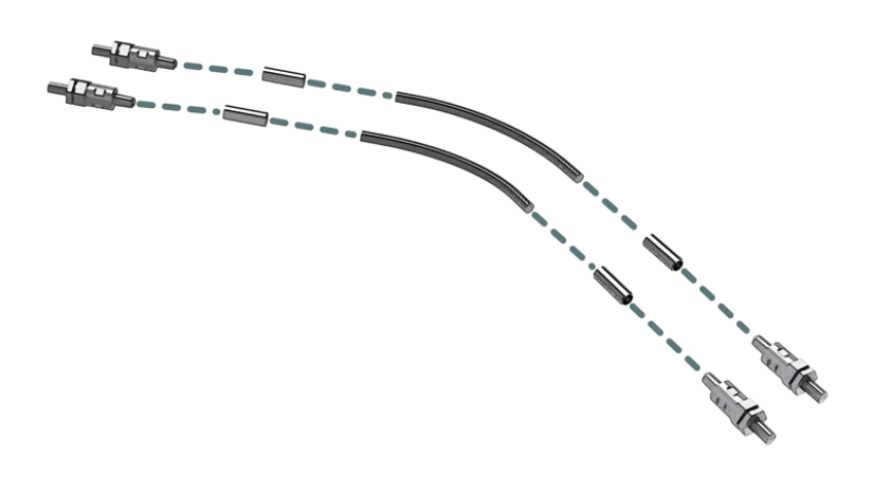
- 66F Metal hose (x 2)
- 66G Connector (x 4)
- 66H Water pipe
- AP Screw M 1,7 x 4 mm (x 3)
- MP Screw M 2,0 x 5 mm (x 3)
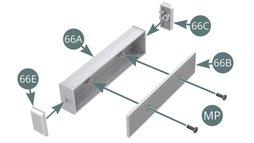
Step 1
Position the radiator front panel (66B) on the water radiator (66A) and secure it with two MP screws. Position the left (66C) and right (66E) sides onto the water radiator (66A).
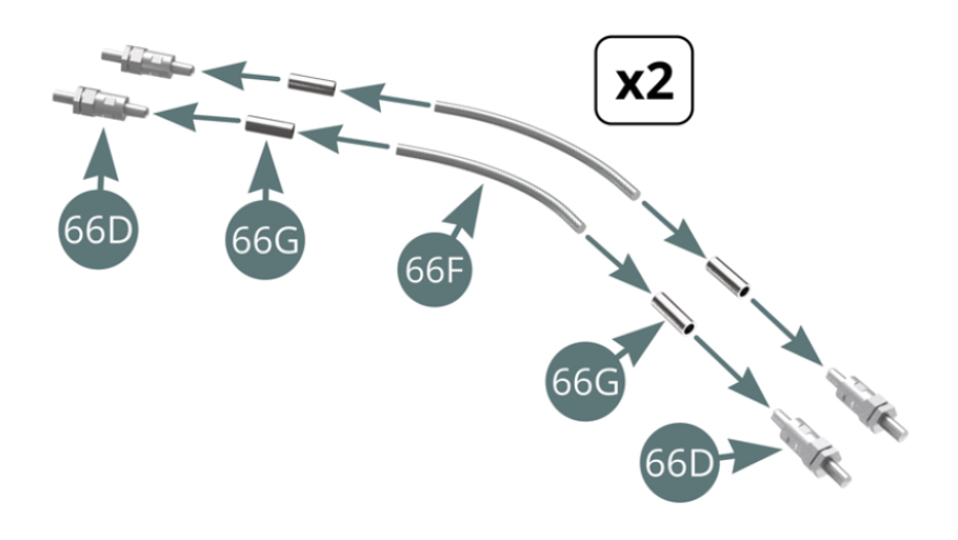
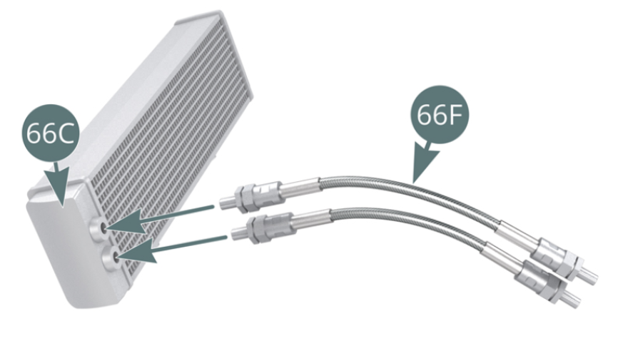
Attach a coupling (66D) and a connector (66G) to each end of the metal hose (66F). Make a second identical assembly.
Step 2
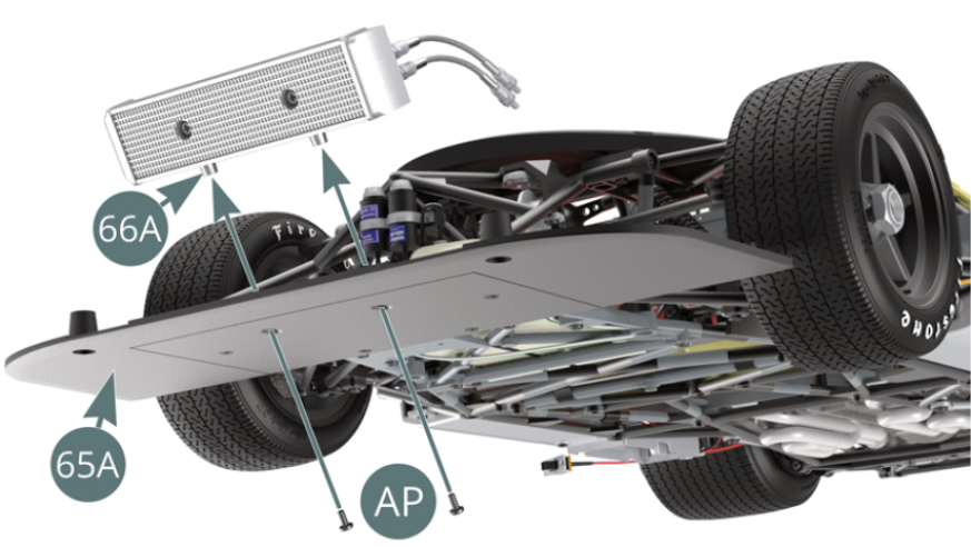
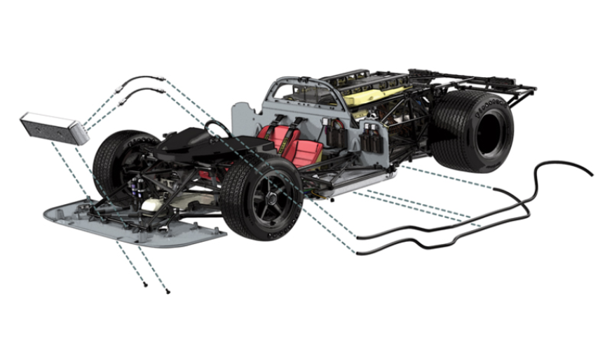
Connect the two metal hoses (66F) to the water radiator (66A) using the two couplings (66D). Position the water radiator (66A) onto the front flat bottom (65A) and secure it with two AP screws.
Step 3
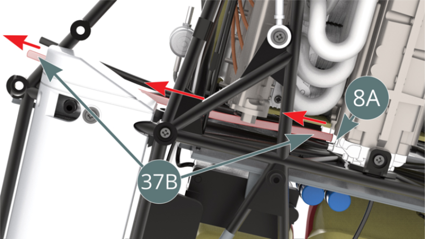
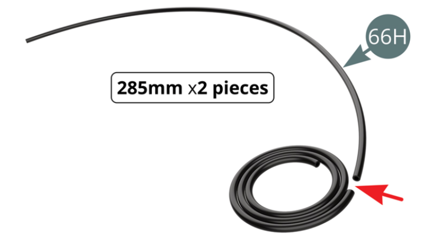
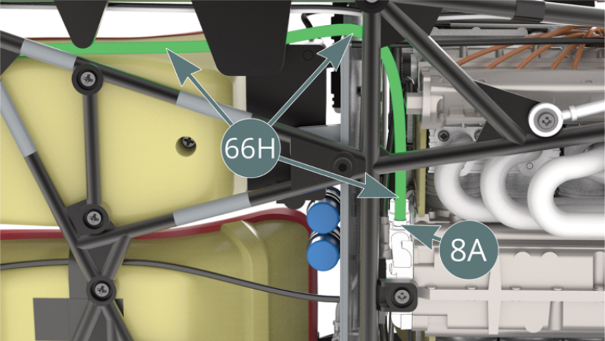
Turn the car upside down and detach the water hose (37B) from the nozzle of the water pump housing (8A) - red arrow - DO NOT remove the second hose (green arrow), as it will be used to connect to the Oil Tank in a later stage. Then cut two lengths each of 285 mm from the water pipe roll (66H).
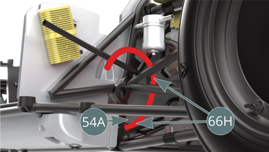
Step 4
Position one of the two cutted lengths of water hose (66H) over the nozzle of the water pump housing (8A) - from which the oil hose (37B) has just been removed - and then run it under the edge of the cockpit bulkhead (54A) - illustrations opposite and below.
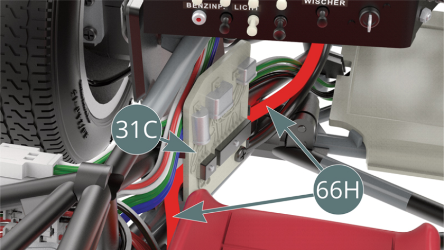
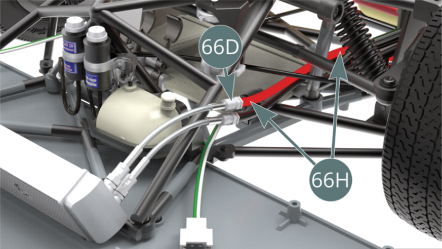
Step 5
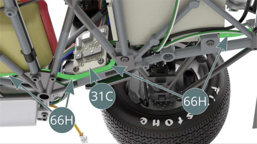
Slide the water hose (66H) underneath the wiring board (31C) before passing it any further. Position the water hose (66H) onto the bottom coupling (66D).
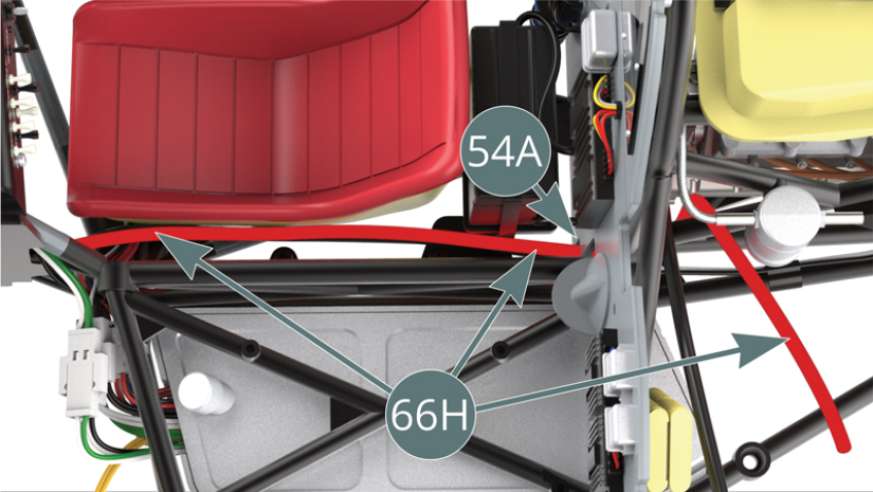
Step 6
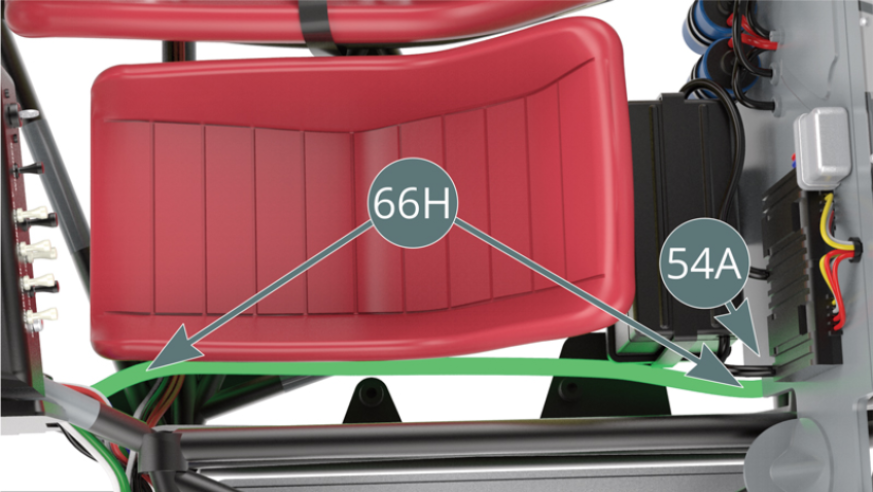
Run the second cut length of the water hose (66H) under the left lower side of the cockpit bulkhead (54A). Leave the end hanging loose, as this will be connected in a later stage. There should be two free water pipes (66H and 37B) as shown. Continue running the water pipe (66H) alongside the passenger seat (shown opposite and below).
Step 7
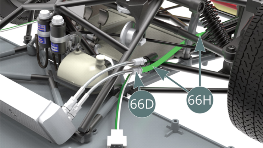
Slide the water hose (66H) behind the wiring board (31C) before extending it further. Position the water hose (66H) onto the top coupling (66D).
ASSEMBLY DIAGRAM

GENERAL VIEW
Kit 67
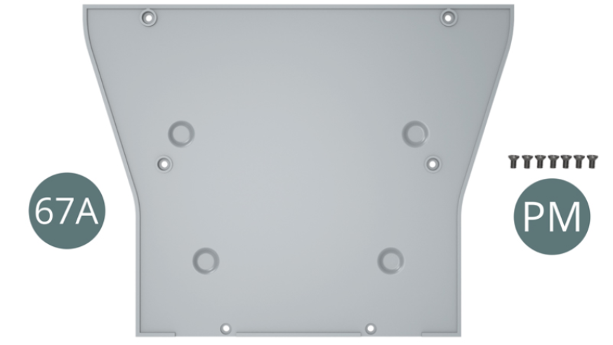
Parts of kit
- 67A Flat cockpit floor
- PM Screw M 2,0 x 4 mm (x 7)
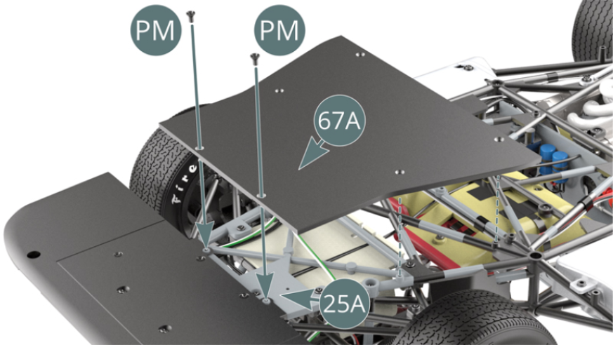
Step 1
Unscrew the two marked CM screws from lower frame (25A).

Step 2
Align and position the flat floor of the cockpit (67A) on the lower frame (25A) and secure it with two PM screws replacing the two CM screws that were just removed.
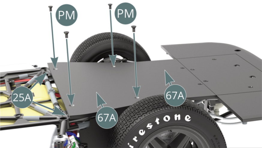
Step 3
Complete the fixation of the flat cockpit floor (67A) to the lower frame (25A) with four additional PM screws.
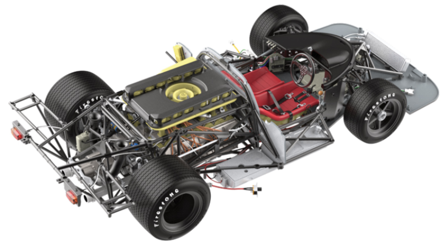
ASSEMBLY DIAGRAM

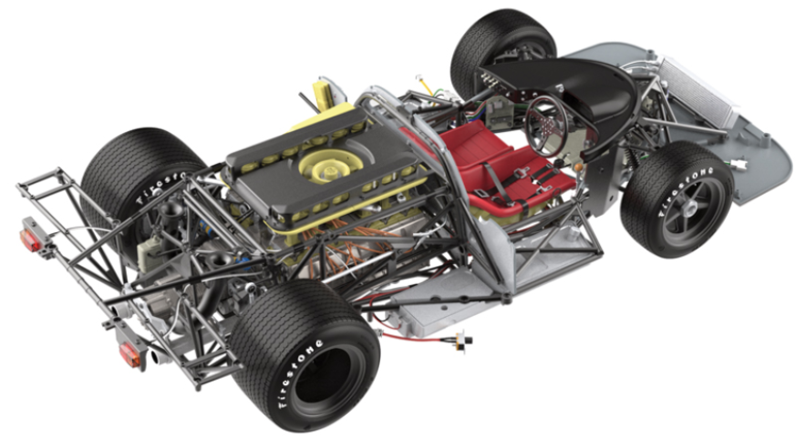
GENERAL VIEW
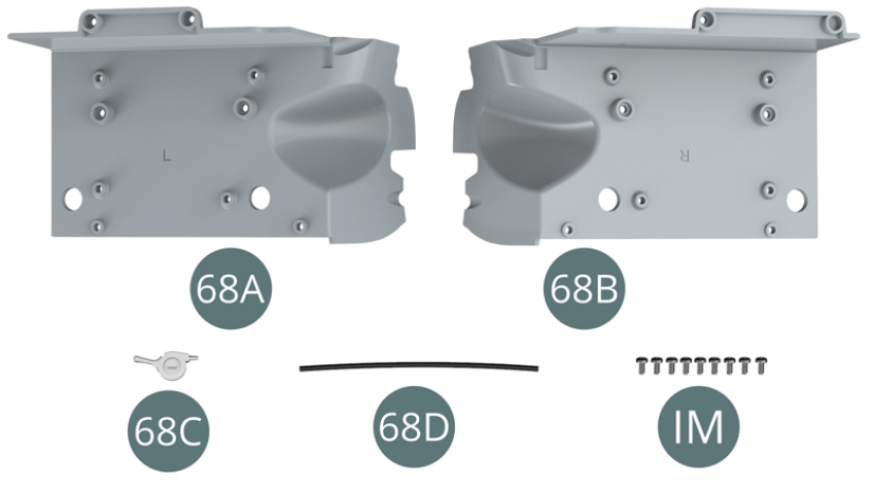
Kit 68
Parts of kit
- 68A Left cockpit housing
- 68B Right cockpit housing
- 68C Handbrake
- 68D Handbrake cable
- IM Screw M 1,7 x 3,5 mm (x 9)
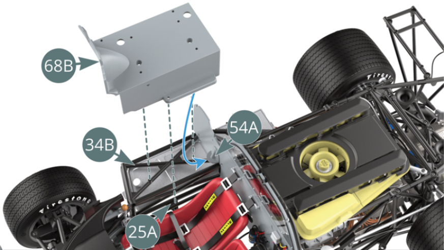
Step 1
Position the right cockpit housing (68B) on the lower frame (25A) and onto the chassis (34B) ensuring that the rear edge slides under the reinforcement of the cockpit bulkhead (54A) - blue arrow.
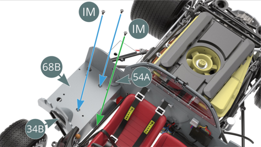
Step 2
Attach the right cockpit housing (68B) to the chassis (34B) with two IM screws (blue arrows) and to the lower frame (25A) with one IM screw (green arrow). Please refer to the illustrations on the right and in the previous step.

Step 3
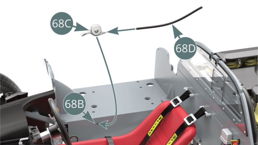
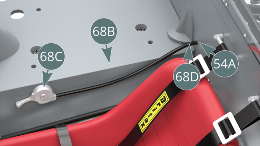
Position the handbrake cable (68D) onto the handbrake (68C), then position the assembly onto the right-hand cockpit housing (68B). Position the free end of the handbrake cable on the pin situated on the cockpit bulkhead (54A).
Step 4
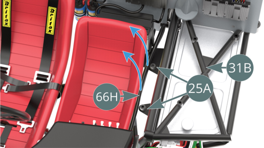
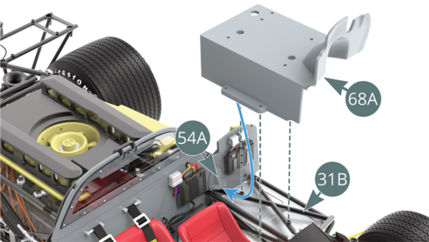
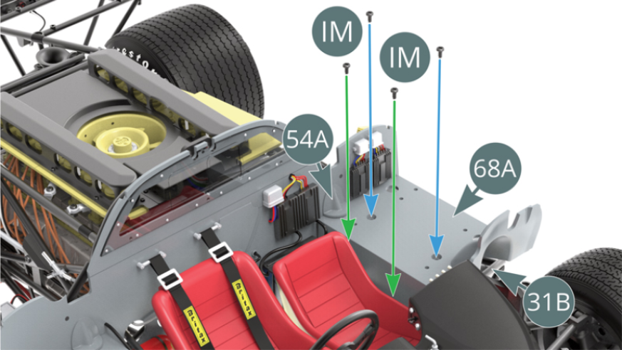
Before installing the left cockpit housing (68A) - shown next - tighten the two water hoses (66H) along the passenger seat. Position the left cockpit housing (68A) onto the lower frame (25A) and chassis (31B), ensuring that the rear edge slides under the reinforcement of the cockpit bulkhead (54A) - blue arrow.
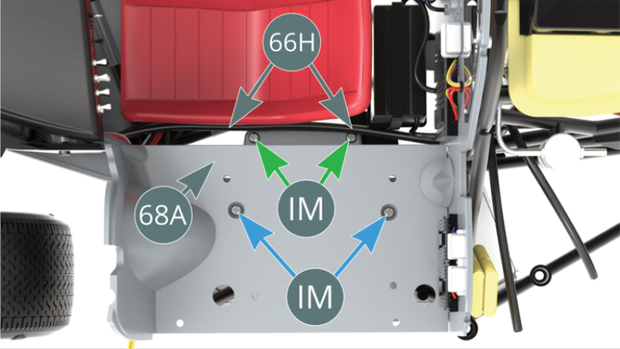
Step 5
Attach the left cockpit housing (68A) onto the chassis (31B) with two IM screws (blue arrows) and onto the lower frame (25A) with one IM screw (green arrows). Consult the illustrations below and in the previous step. Replace the two water hoses (66H) against the left cockpit housing (68A).
ASSEMBLY DIAGRAM
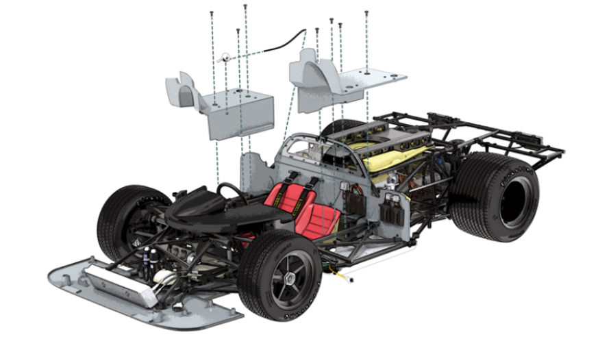
GENERAL VIEW