English
 français
 Deutsch
 español
 italiano
 português


Box 18
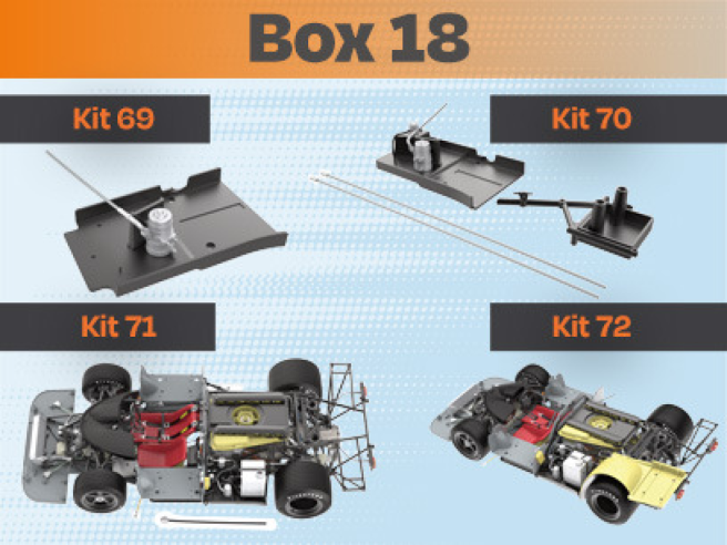
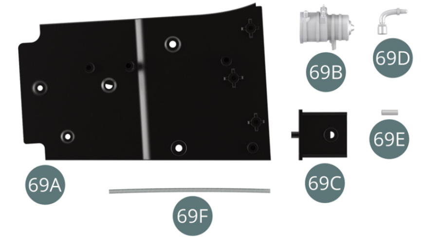
Kit 69
Parts of kit
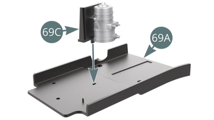
- 69A Platform left side
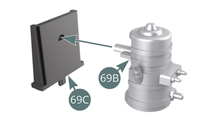
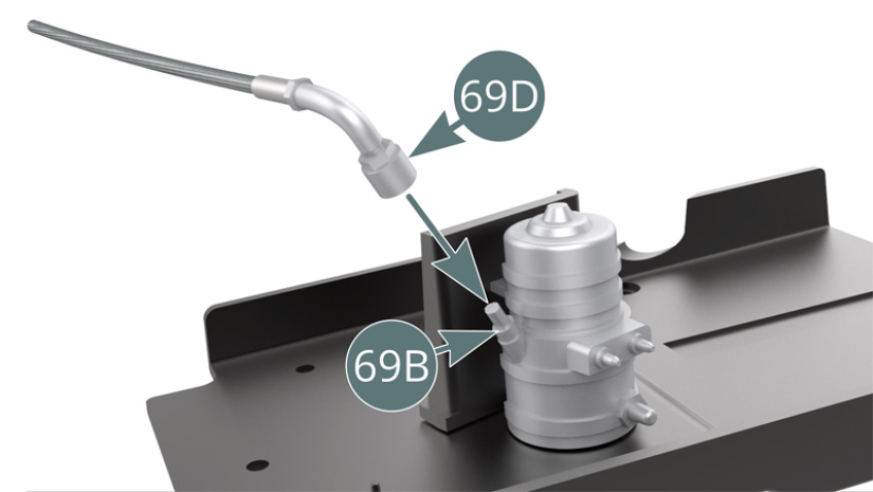
- 69B Fuel pump
- 69C Protective shield
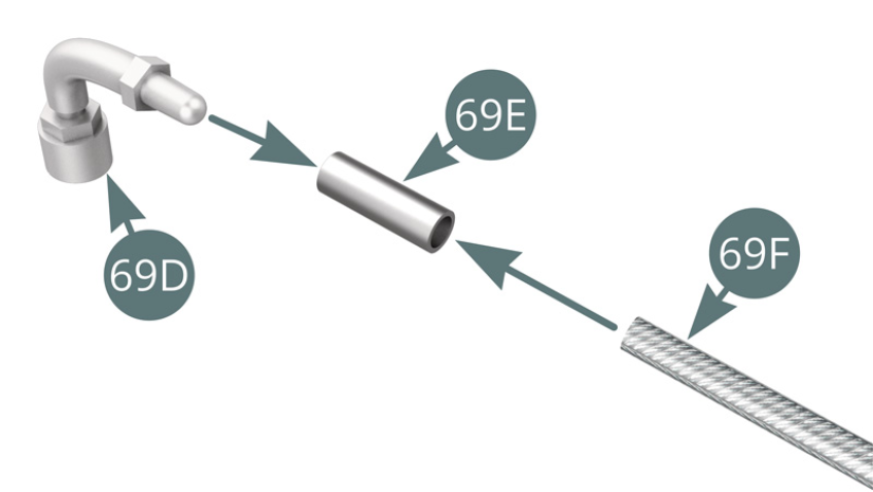
- 69D Pump coupling
- 69E Connector
- 69F Shielded/Protected fuel line
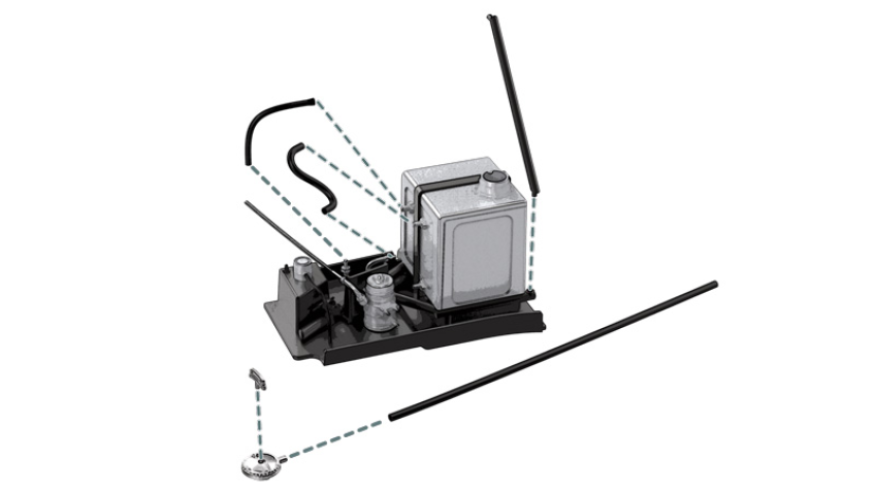
Step 1
Position the fuel pump (69B) on the protective shield (69C). Position the shield (69C) and pump onto the left side platform (69A).
Step 2
Position the shielded fuel line (69F) onto the pump coupling (69D) via the connector (69E). Position the pump connector (69D) onto the fuel pump (69B).
ASSEMBLY DIAGRAM
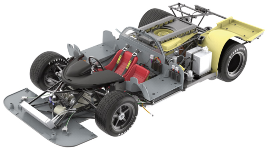
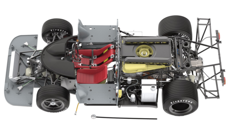
GENERAL VIEW
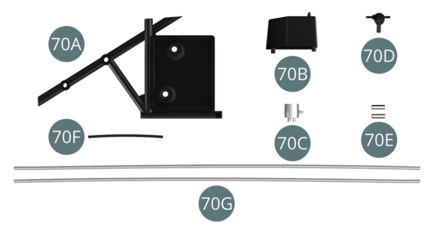
Kit 70
Parts of kit
- 70A Oil tank support frame
- 70B Fuel manifold
- 70C Cap
- 70D Electrical switch
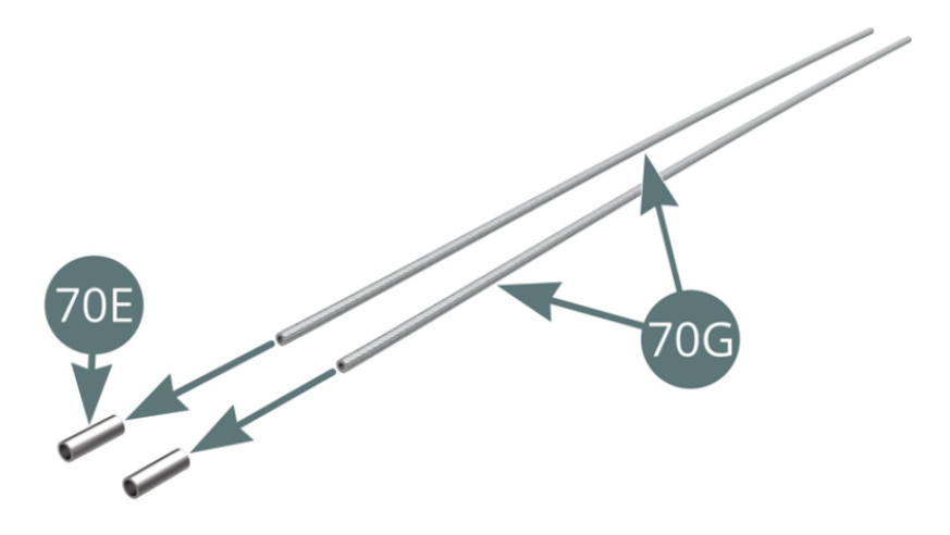
- 70E Fitting (x 2)
- 70F Fuel hose
- 70G Shielded fuel line (x 2)
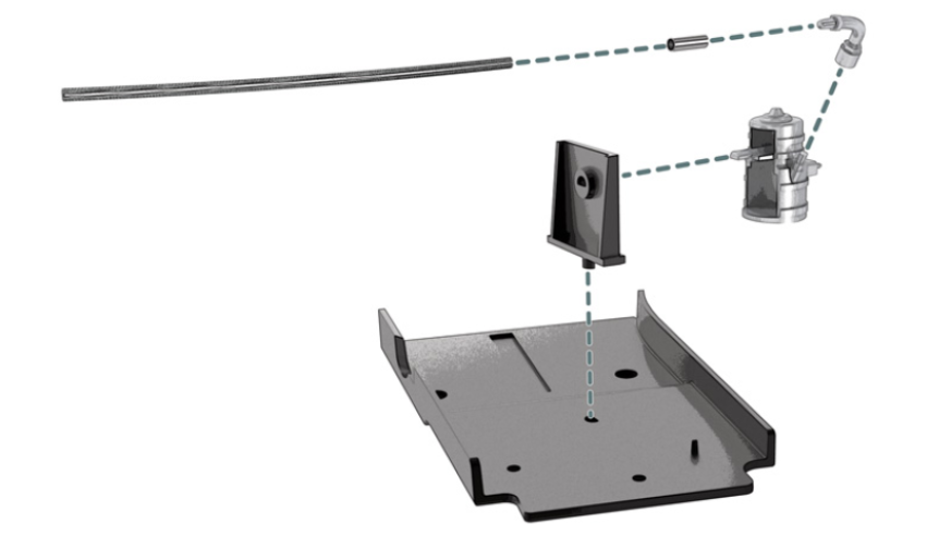
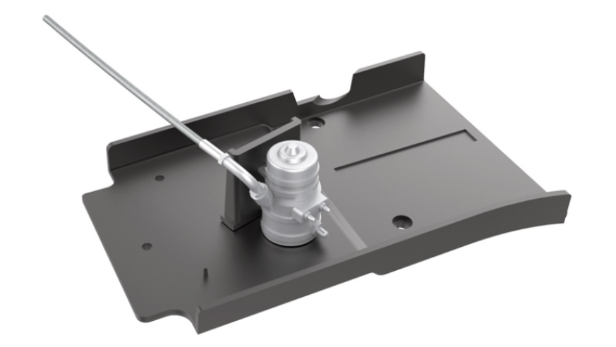
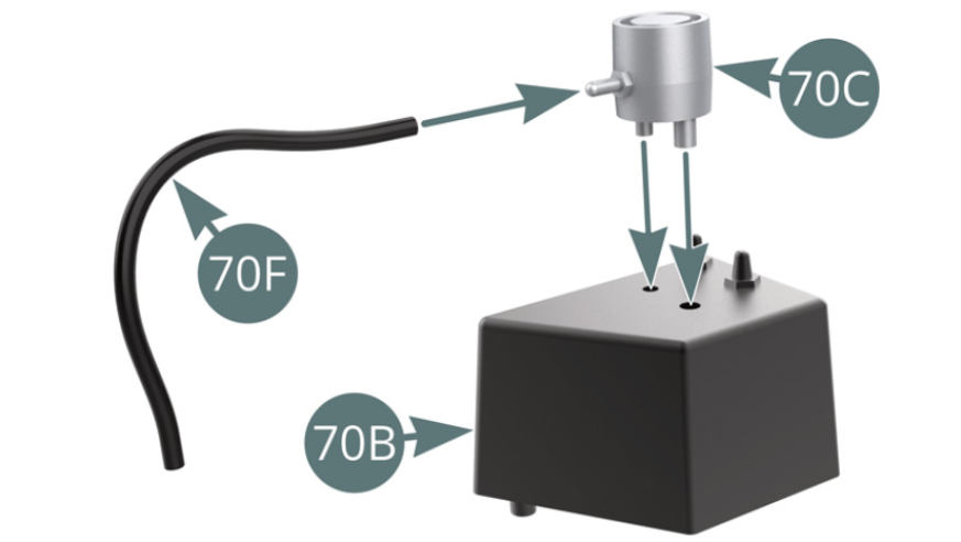
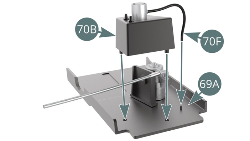
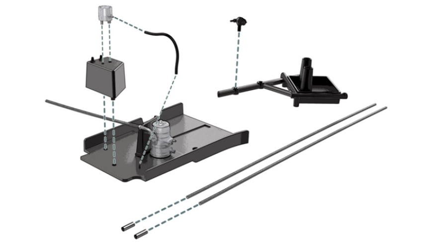
Step 1
Position the fuel hose (70F) onto the fuel cap (70C). Position the cap (70C) onto the fuel manifold (70B). Position the fuel manifold (70B) on the left side platform (69A). Connect the fuel hose (70F) to the pin positioned on the left side platform (69A).
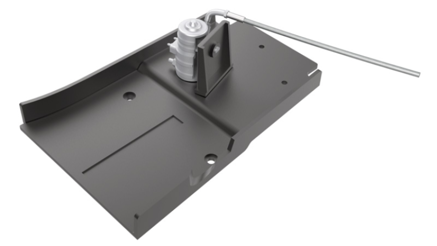
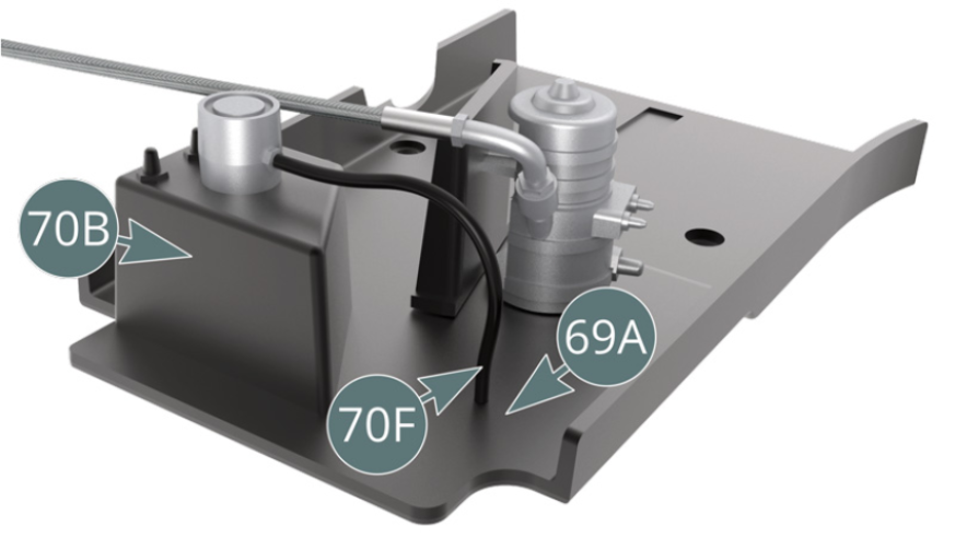
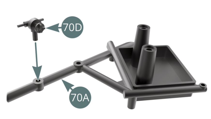
Step 2
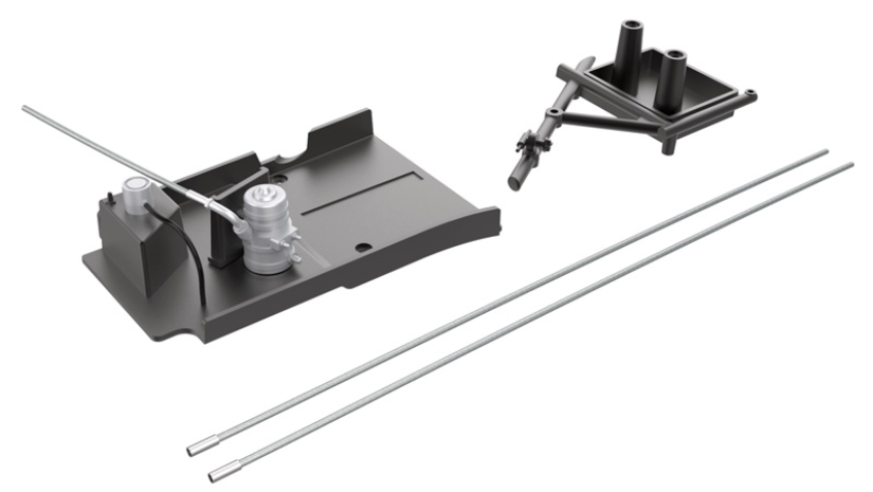
The fuel manifold (70B) and fuel hose (70F) are attached to the left side platform (69A). Position the electrical switch (70D) on the oil tank support frame (70A).
Step 3
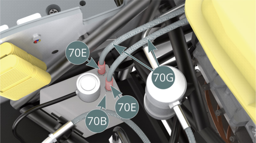
Position the two connectors (70E) on the two shielded fuel lines (70G).
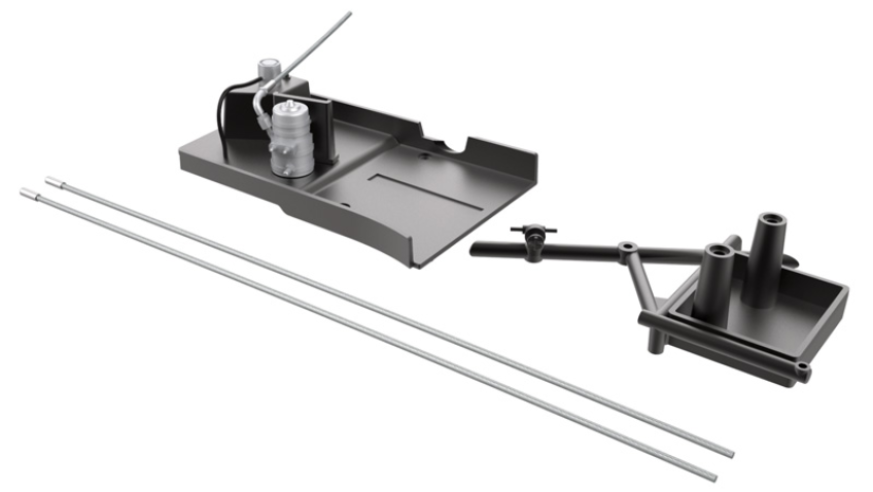
ASSEMBLY DIAGRAM
GENERAL VIEW
Kit 71
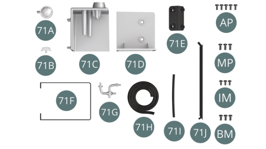
Parts of kit
- 71A Oil filler cap
- 71B Handle
- 71C Oil tank body
- 71D Oil tank body
- 71E Bracket
- 71F Strap
- 71G Thermostat
- 71H Oil hose
- 71I Oil hose
- 71J Arm
- AP Screw M 1.7 x 4 mm (x 5)
- MP Screw M 2.0 x 5 mm (x 3)
- IM Screw M 1.7 x 3.5 mm (x 3)
- BM Screw M 2.0 x 4 mm (x 3)
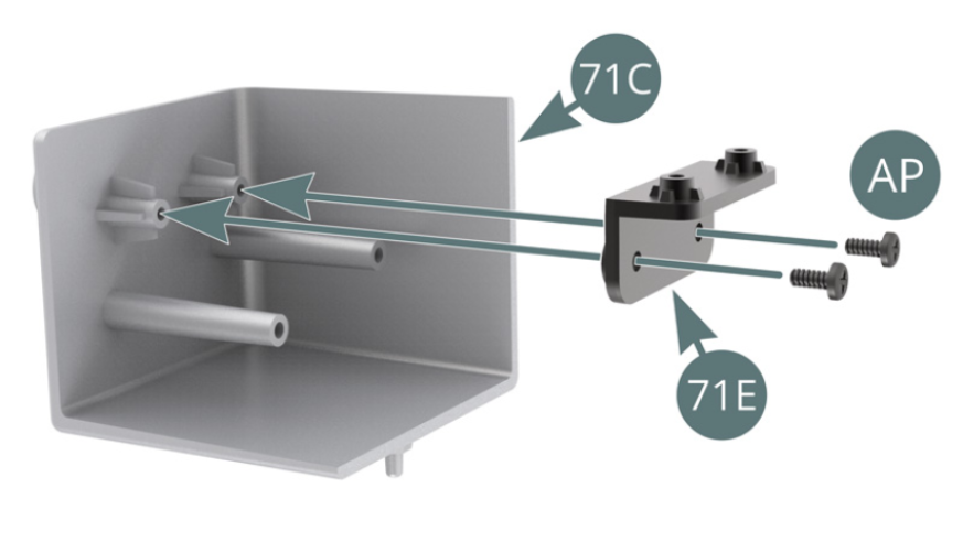
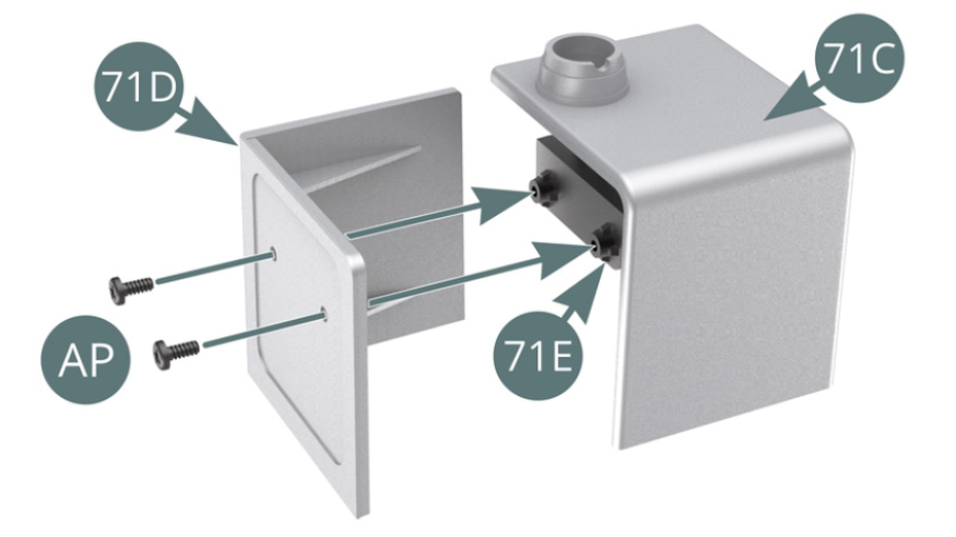
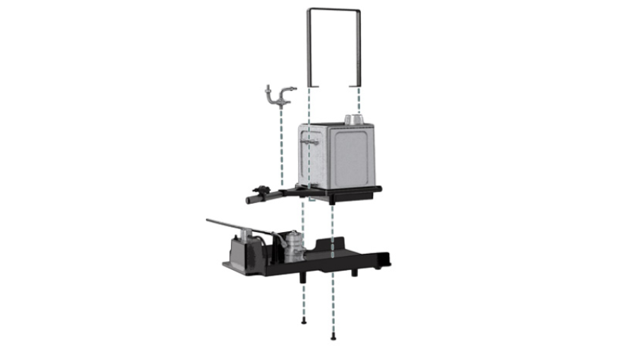
Step 1
Position the bracket (71E) on the oil tank body (71C) and secure it with two AP screws. Position the oil tank body (71D) on the bracket (71E) and secure with two AP screws.
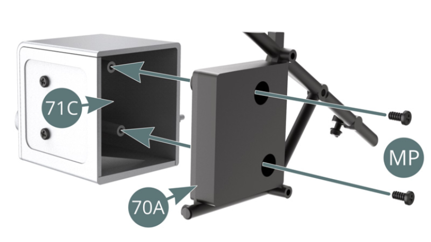
Step 2
Position the oil tank support frame (70A) on the oil tank body (71C) and secure with two MP screws. Position the thermostat (71G) on the tubular bar of the oil tank support frame (70A). Place the strap (71F) over the oil tank (71C) and the oil tank support frame (70A)
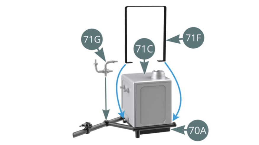
Step 3
Position the oil tank support frame (70A) on the left side platform (69A) and fix with two IM screws. Cut two sections of oil hose 71H: 71H-1 = 140 mm and 71H-2 = 40 mm.


Step 4
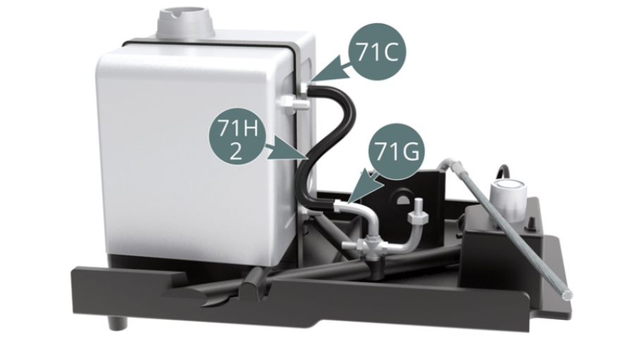
Position the oil hose (71H-1) and handle (71B) on the filler cap (71A). Position the oil hose (71H-2) between the oil tank nozzle (71C) and the thermostat (71G).

Step 5
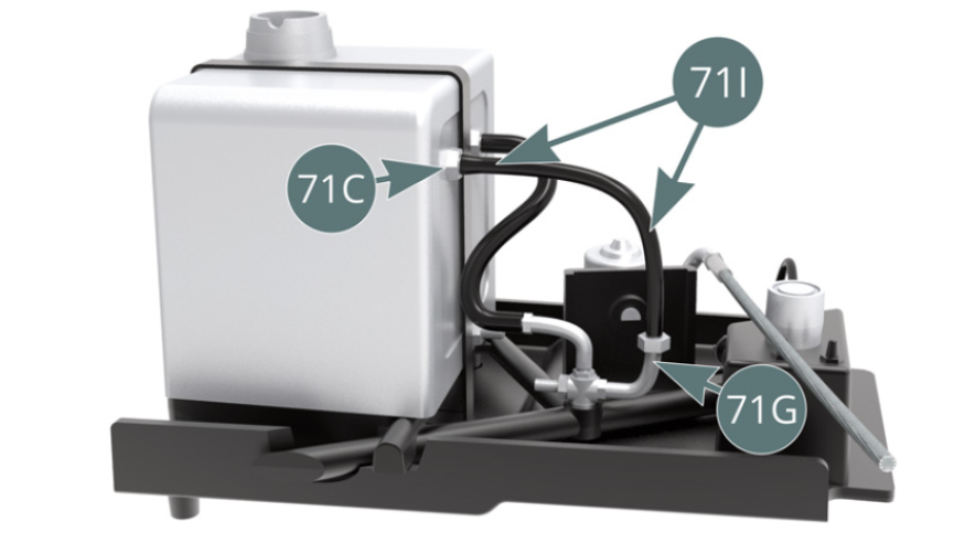
Position the oil hose (71I) between the oil tank nozzle (71C) and the thermostat (71G).
Step 6
Position the arm (71J) - the end with the smallest peg - over the oil tank support frame (70A) and along the oil tank (71D).

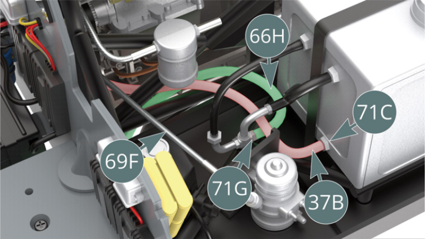
Step 7
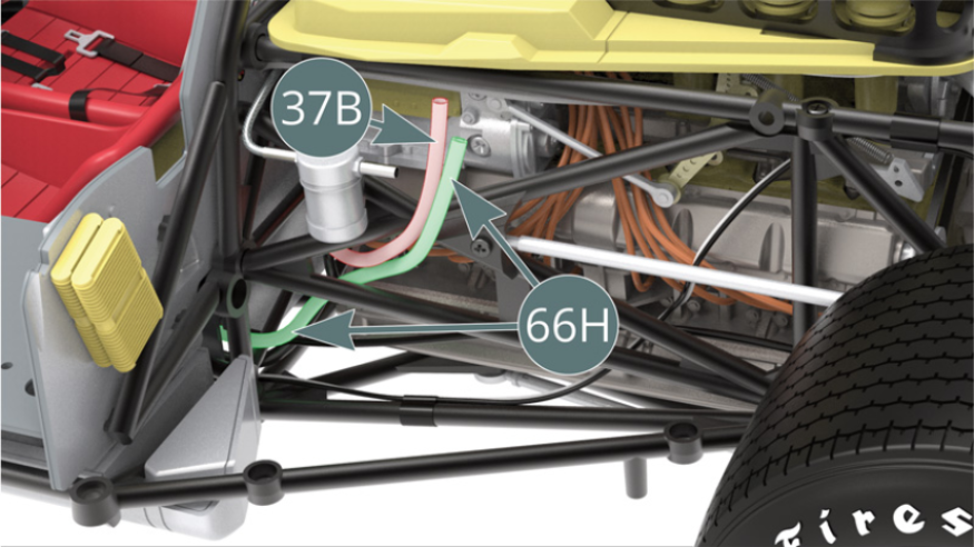
Point the oil line (37B) - highlighted in red - and the water line (66H) - highlighted in green - upwards as shown.
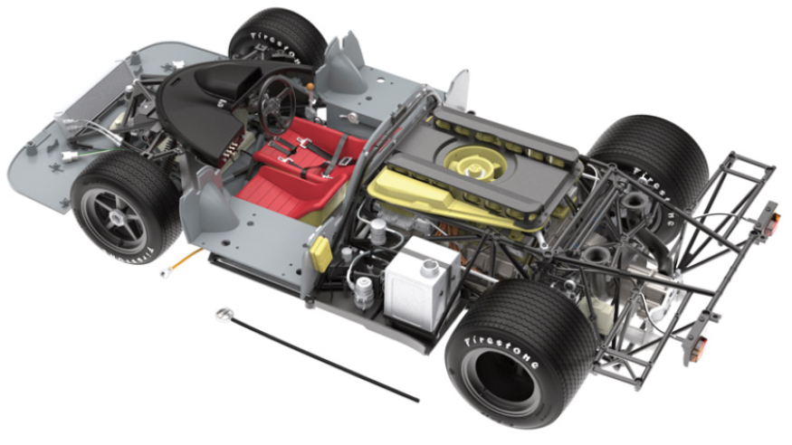
Step 8
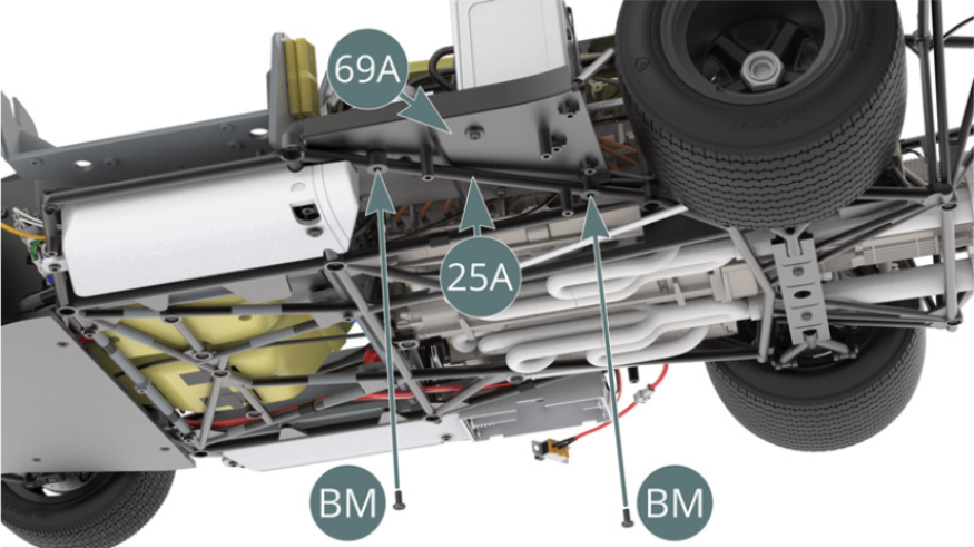
Position the left side platform (69A) on the lower frame (25A), placing the end of the arm (71J) in the slot located on the upper frame (47A).

Step 9
Attach the left side platform (69A) to the lower frame (25A) with two screws BM.
Step 10
Position the water hose (66H) - highlighted in green - on the thermostat (71G) and the oil hose (37B) - highlighted in red - on the oil tank nozzle.
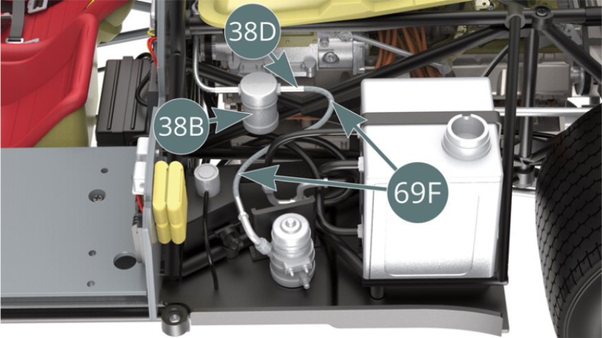
Step 11
Position the shielded fuel line (69F) onto the connector (38D) of the fuel filter (38B).
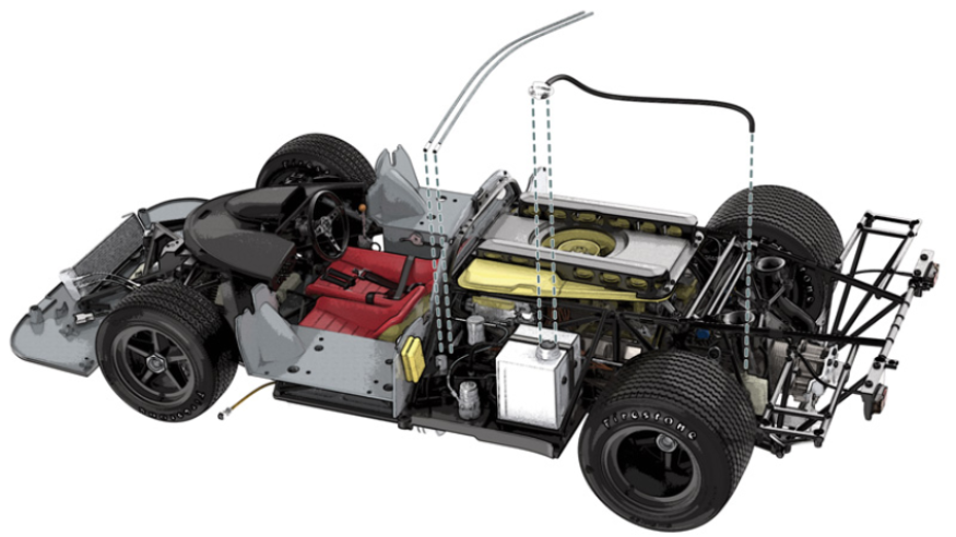
ASSEMBLY DIAGRAM
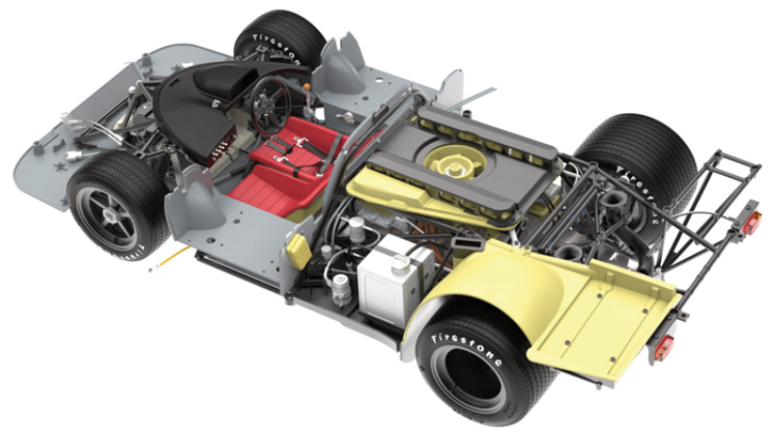
GENERAL VIEW
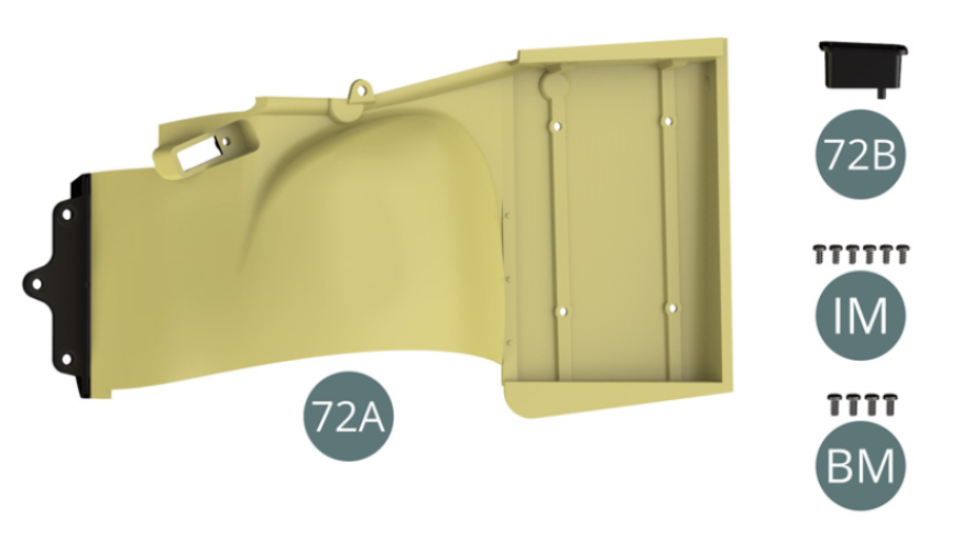
Kit 72
Parts of kit
- 72A Left rear wheel arch
- 72B Rear brake cooling valve
- IM Screw M 1.7 x 3.5 mm (x 6)
- BM Screw M 2.0 x 4 mm (x 4)
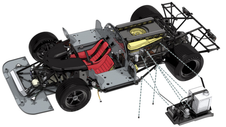
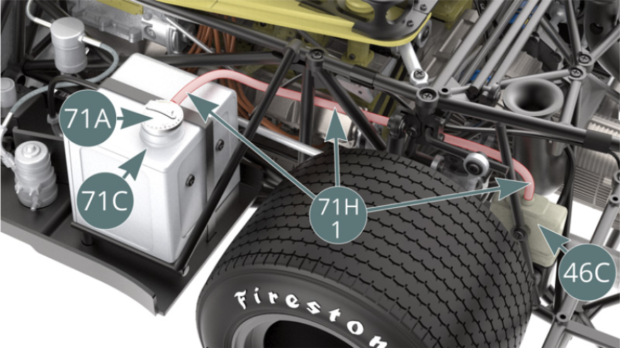
Step 1
Position the oil filler cap (71A) on the oil tank (71C) and guide the oil hose (71H-1) - highlighted in red - through the engine tube frame to secure it above the engine oil tank cover (46C)
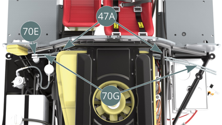
Step 2
Guide the two shielded fuel lines (70G) (with their 70E fittings) to the left side and front of the engine, passing over the tubular bars of the upper frame (47A). Position the two fittings (70E) - highlighted in red - of the shielded fuel lines (70G) on the fuel manifold (70B) - highlighted in grey.
Step 3
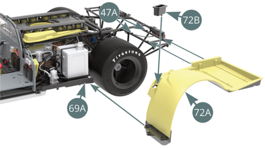
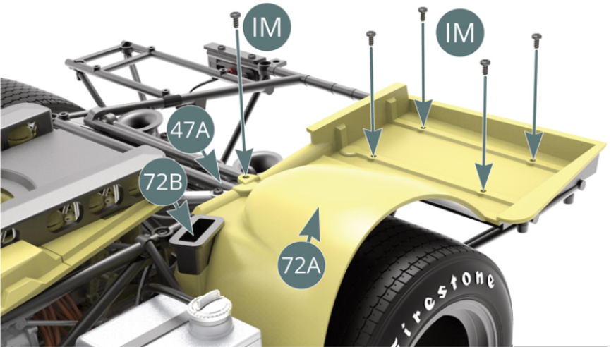
Position the rear brake cooling valve (72B) on the left rear wheel arch (72A). Position the left rear wheel arch (72A) on the upper frame (47A), placing its front bracket under the left lateral platform (69A). Secure the left rear wheel arch (72A) to the upper frame (47A) with five IM screws.
Step 4
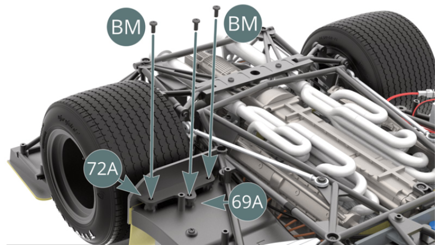
Flip the car over and secure the front left rear wheel arch support (72A) to the left side platform (69A) with three BM screws.
ASSEMBLY DIAGRAM
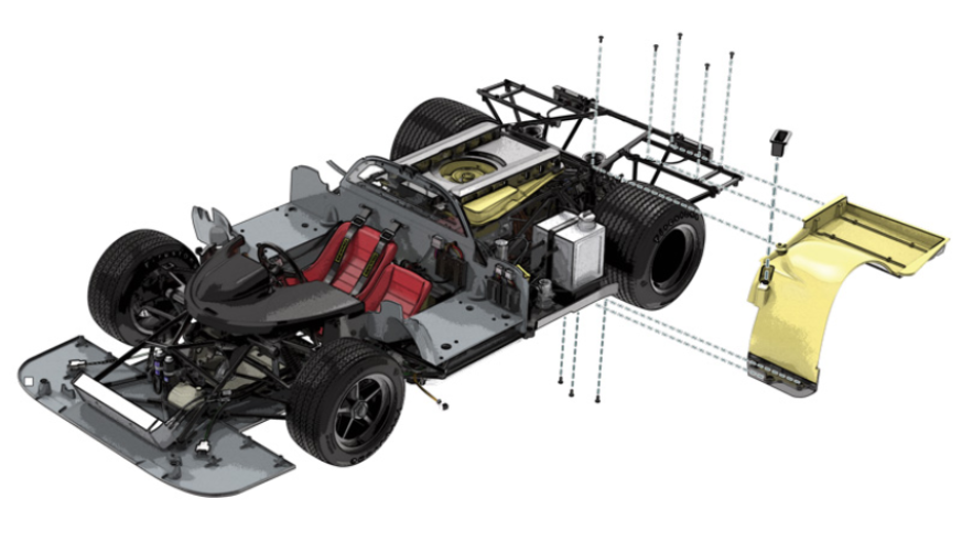
GENERAL VIEW