English
 français
 Deutsch
 español
 italiano
 português


Box 19

Kit 73
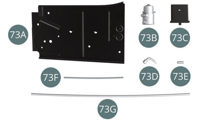
Parts of kit
- 73A Platform right side
- 73B Fuel pump
- 73C Protective shield
- 73D Pump coupling
- 73E Connector
- 73F Shielded fuel line
- 73G Fuel line
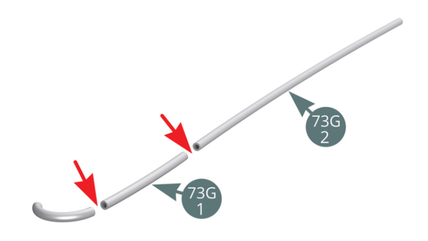
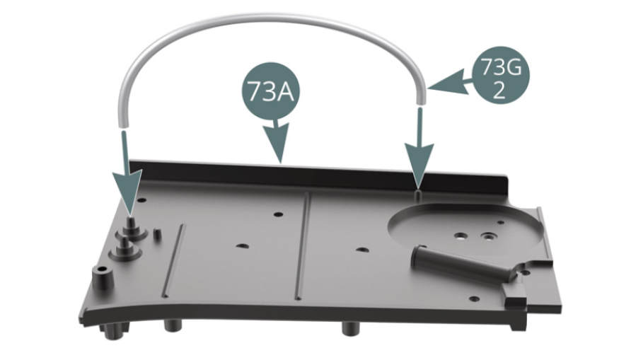
Step 1
Cut two sections from the fuel line (73G): 73G-2 90 mm and 73G-1 50 mm. Connect the fuel line (73G-2) onto the nipples of the right side platform (73A).
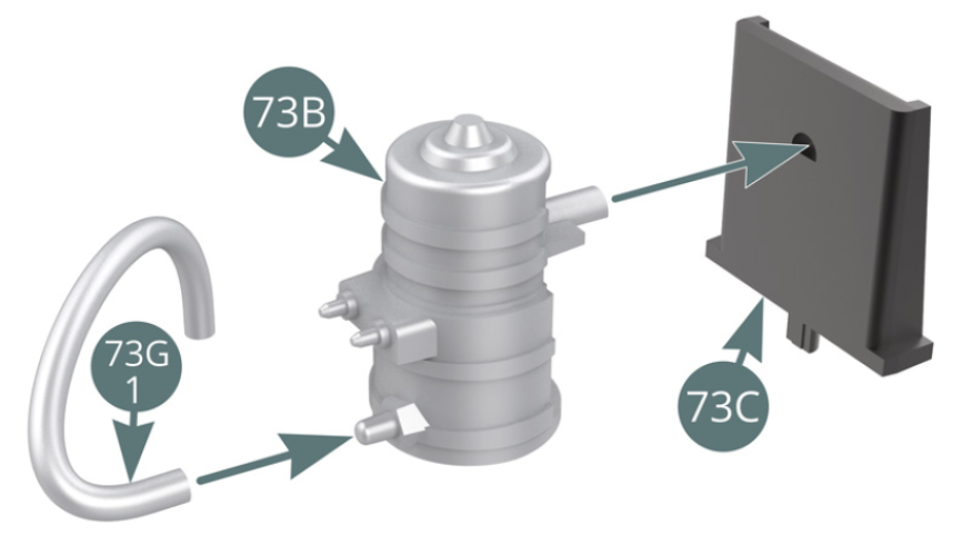
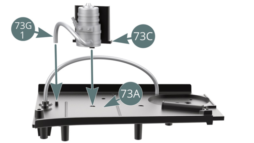
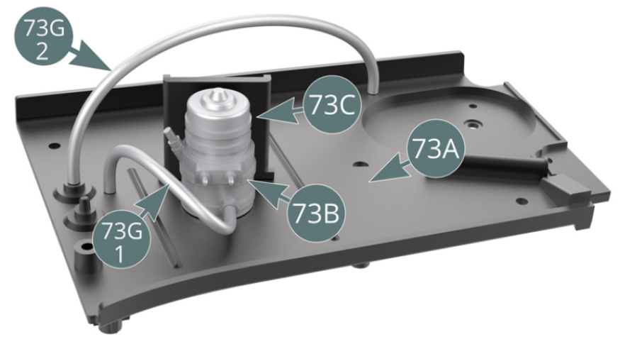
Step 2
Position the fuel pump (73B) on the protective shield (73C) after connecting the fuel line (73G-1) to the nipple located at the bottom of the pump. Position the protective shield (73C) on the right side platform (73A) and connect the fuel line (73G-1) to the nipple shown.
Step 3
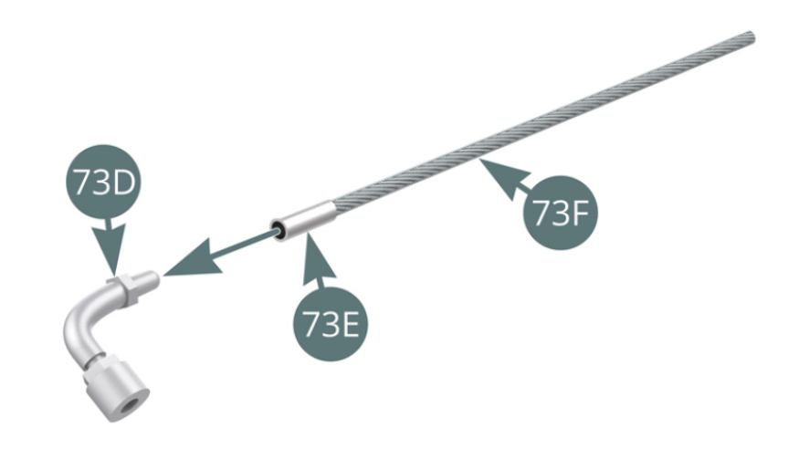
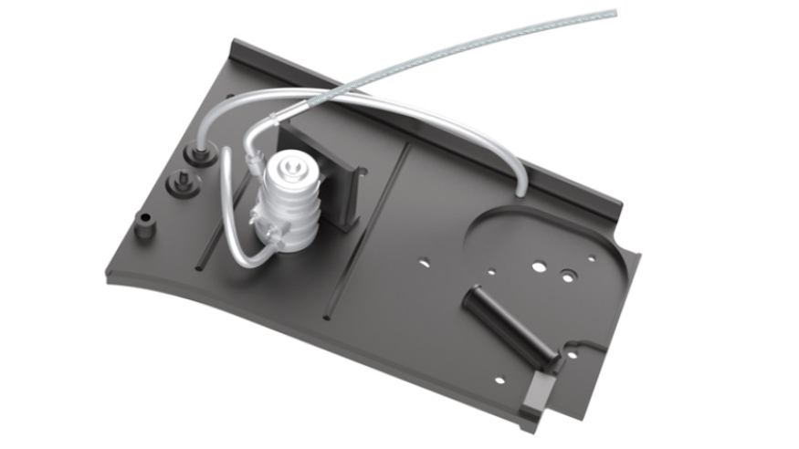
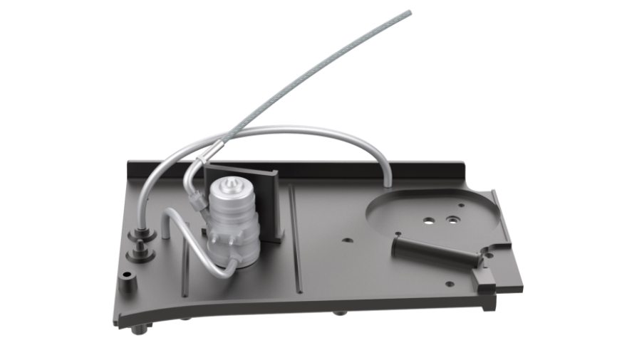
The fuel pump (73B) is installed onto the right side platform (73A). Position the shielded fuel line (73F) onto the pump coupling (73D) via the coupling (73E).
Step 4
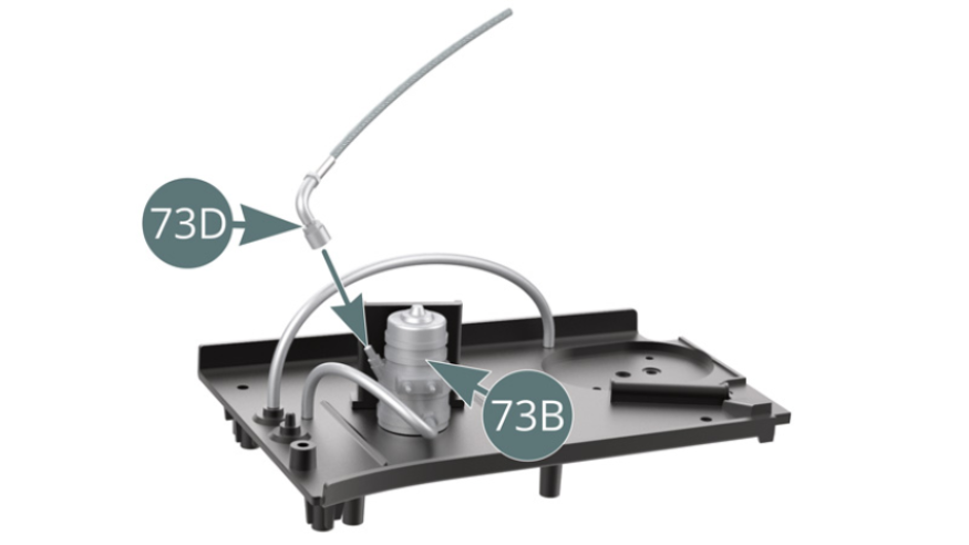
Position the pump coupling (73D) on the fuel pump (73B).
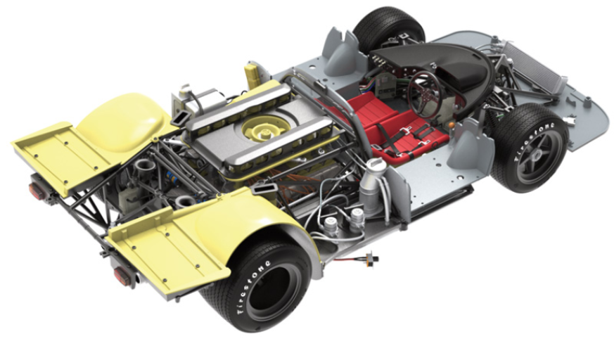
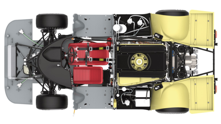
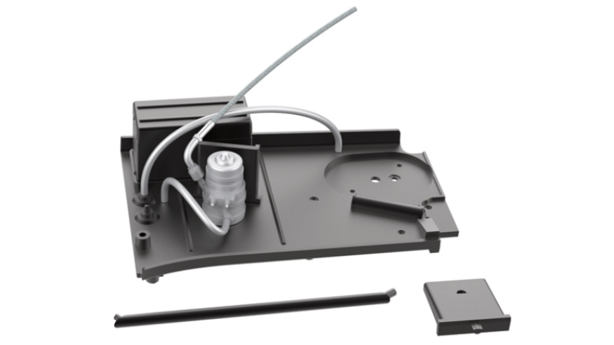
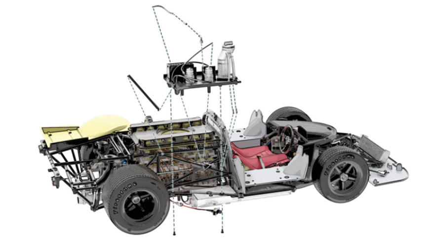
ASSEMBLY DIAGRAM
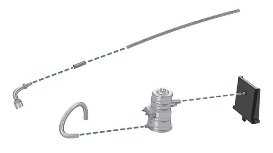
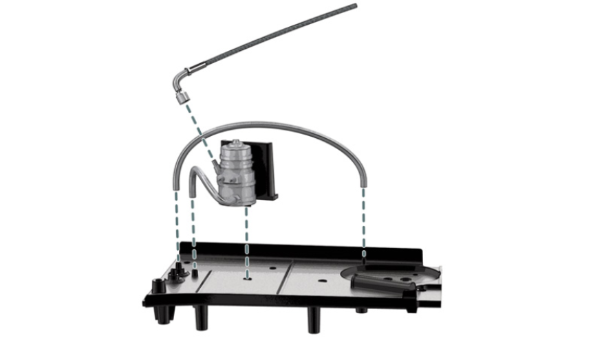
GENERAL VIEW
Kit 74
Parts of kit
- 74A Battery
- 74B Battery holder
- 74C Battery cover
- 74D Battery terminal (x 2)
- 74E Arm
- 74F Protective shield
- LP Screw M 1.2 x 3.5 mm (x 3)

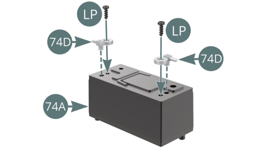
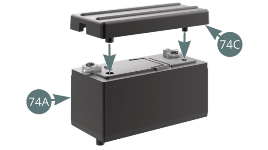
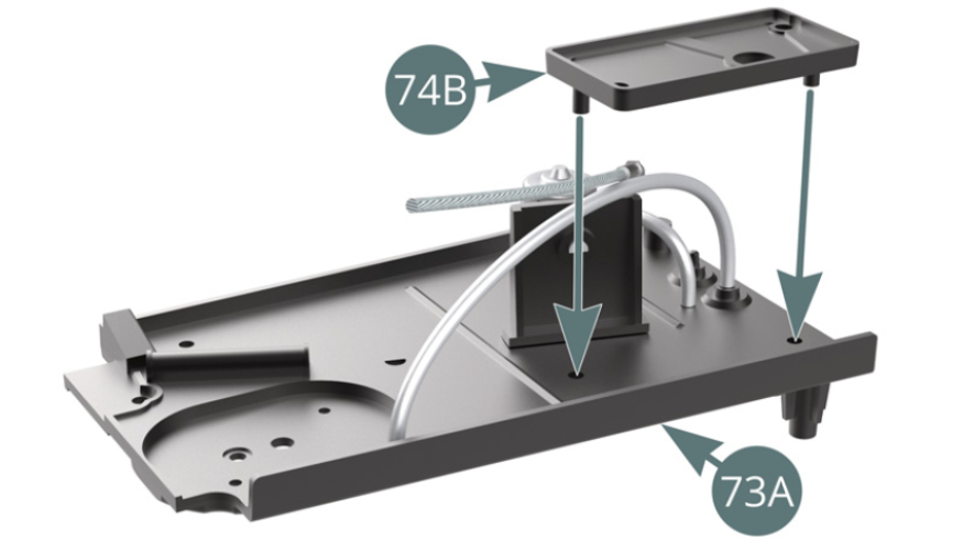
Step 1
Position the two battery terminals (74D) on top of the battery (74A) and secure with two LP screws. Place the cover (74C) on the battery (74A).
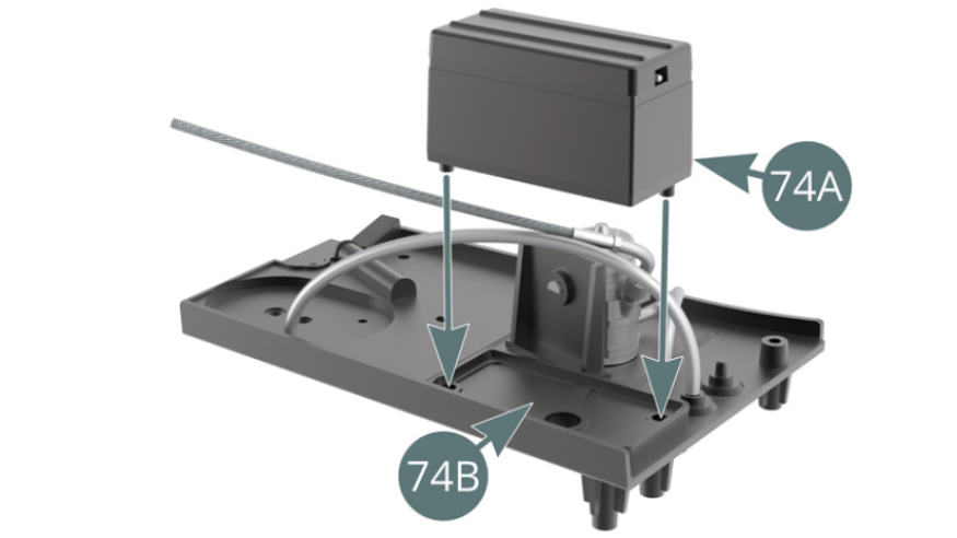
Step 2
Position the battery holder (74B) on the right side platform (73A). Position the battery (74A) on the battery holder (74B).
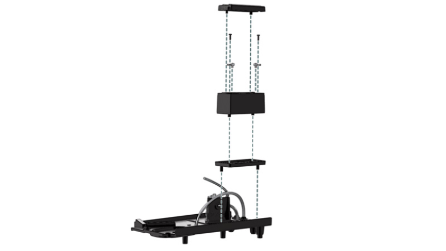
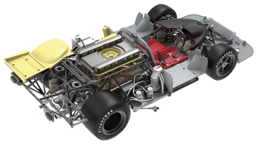
ASSEMBLY DIAGRAM
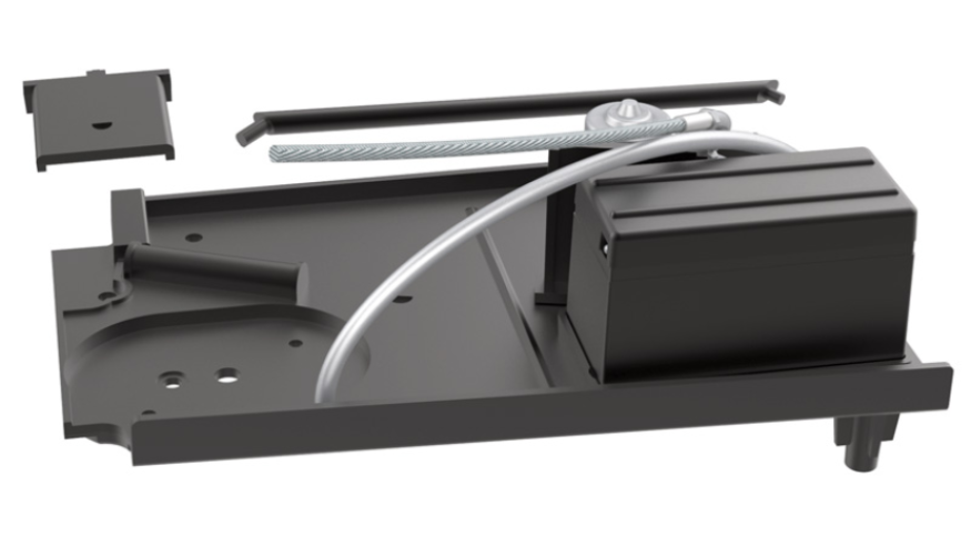
GENERAL VIEW
Kit 75
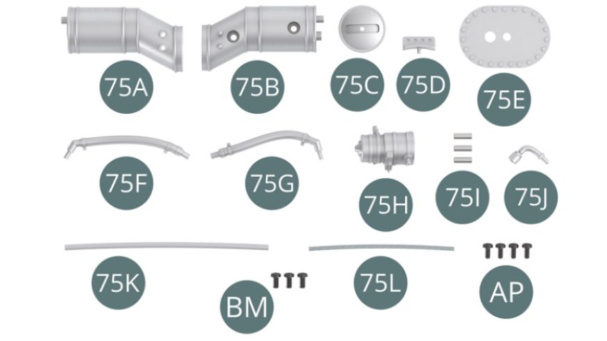
Parts of kit
- 75A Fuel filler neck
- 75B Fuel filler neck
- 75C Fuel filler cap
- 75D Handle
- 75E Tray
- 75F Discharge pipe
- 75G Discharge pipe
- 75H Fuel pump
- 75I Connector (x 3)
- 75J Pump connector
- 75K Fuel line
- 75L Shielded fuel line
- BM Screw M 2.0 x 4 mm (x 3)
- AP Screw M 1.7 x 4 mm (x 4)
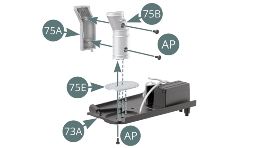
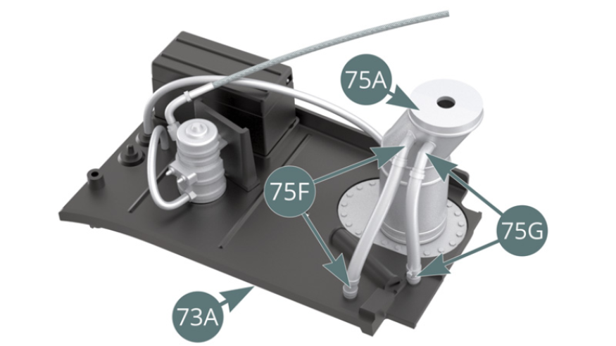
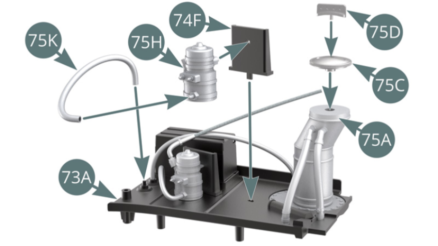
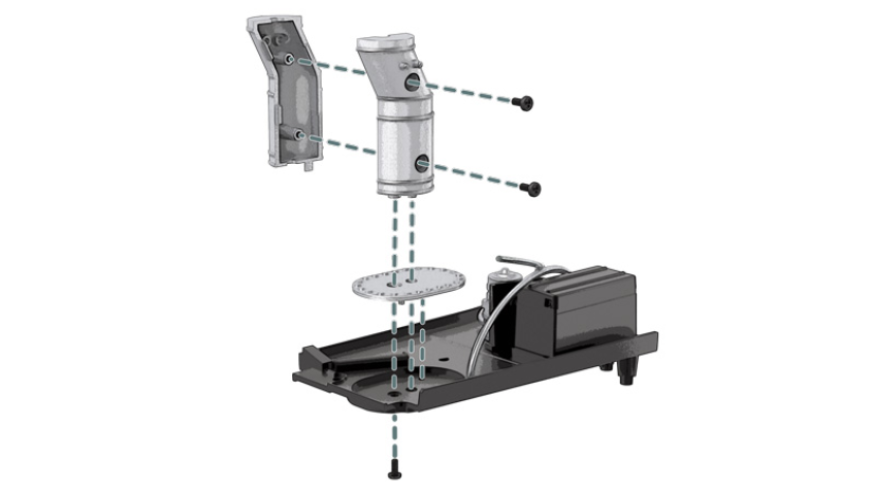
Step 1
Assemble the two filler neck halves (75A & 75B) and secure with two AP screws. Position the filler neck (75B) on the right side platform (73A), inserting the tray (75E), and secure with an AP screw. Connect the discharge hoses (75F & 75G) to the filler neck (75A) and the nipples on the side platform.
Step 2
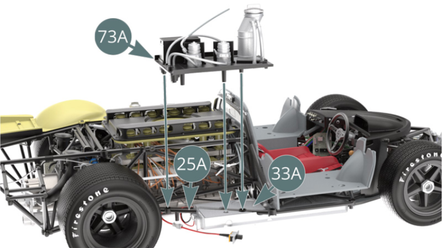
Position the handle (75D) on the filler cap (75C), then position the filler cap onto the filler neck (75A). Position the fuel pump (75H) on the protective shield (74F). Connect the fuel line (75K) to the pump (75H). Position the protective shield (74F) on the right side platform (73A) and connect the free end of the fuel line (75K) to the designated nipple. Position the right side platform (73A) on the crossbar of the lower frame (25A) and the top panel (33A) of the right fuel tank.
Step 3
Position the oil hose (71H-1) and handle (71B) on the filler cap (71A). Position the oil hose (71H-2) between the nozzle of the oil tank (71C) and the thermostat (71G).
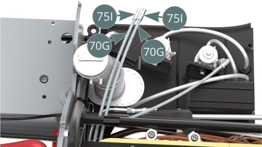
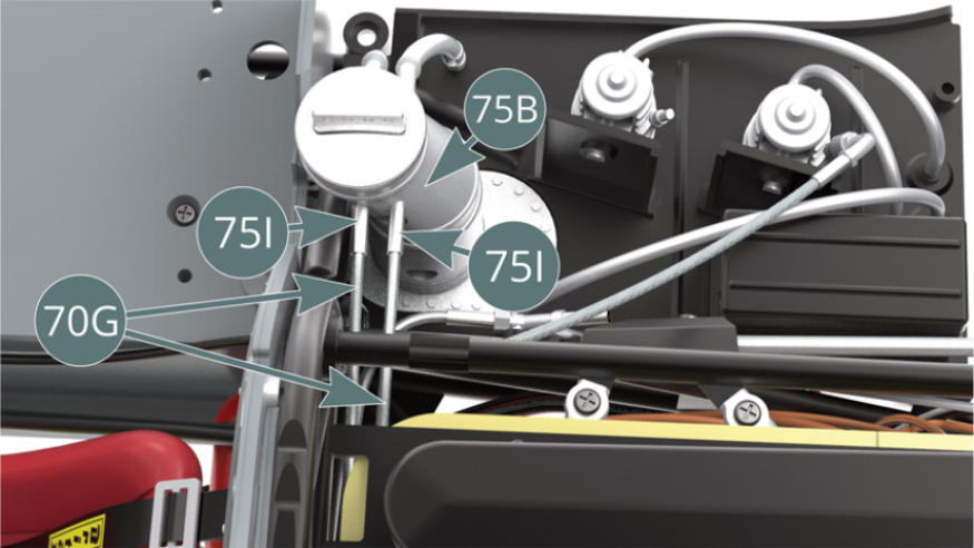
Step 4
Connect the two shielded fuel lines (70G) to the nipples at the filler neck (75B) via the connectors (75I). Position the shielded fuel line (75L) onto the pump connector (75J) via the connector (75I).

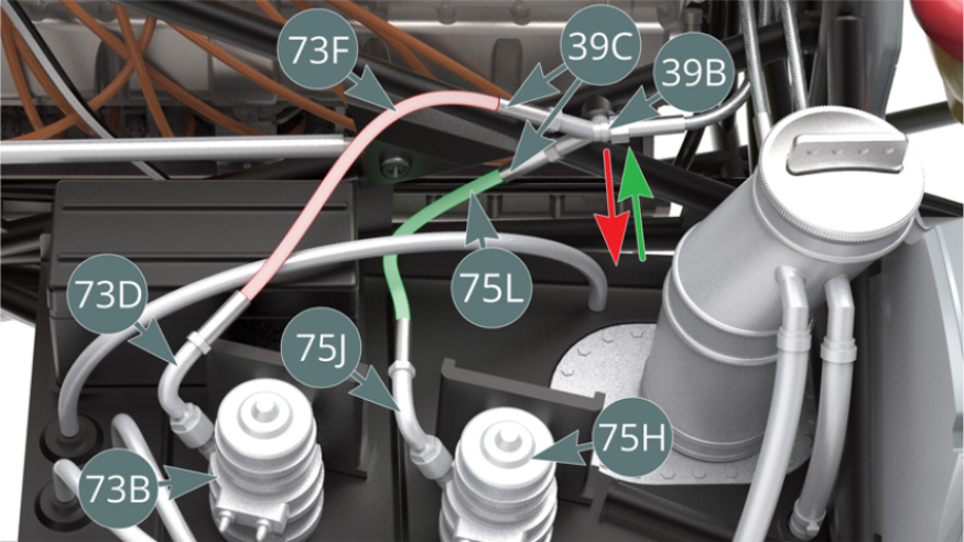
Step 5
Detach the oil hose (39B) from the frame (39A) - red arrow - to facilitate connection of the shielded fuel lines (73F & 75L) to the two connectors (39C). Position the pump connector (75J) onto the fuel pump (75H). Replace the hose (39B) on the frame bar (39A) - green arrow, illustrations above. Position the arm (74E) between the upper frame bar (47A) and the corner of the right side platform (73A) using the nipples provided.

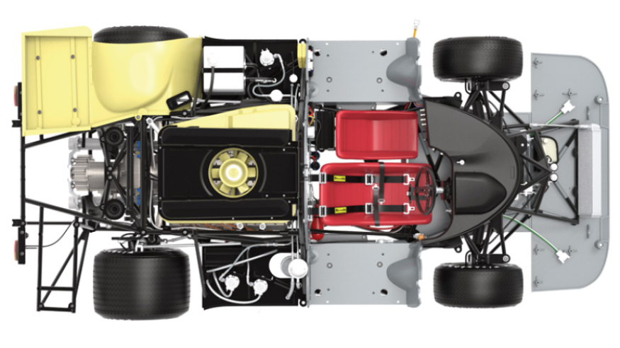
ASSEMBLY DIAGRAM
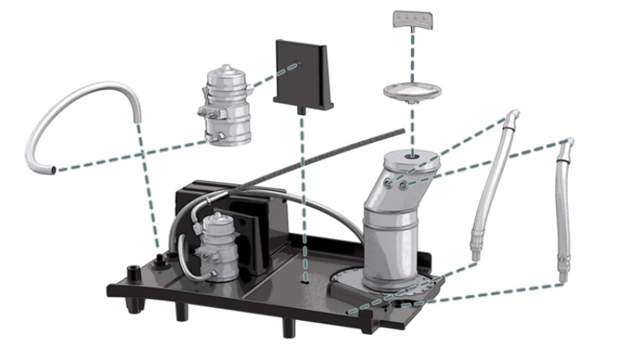
GENERAL VIEW
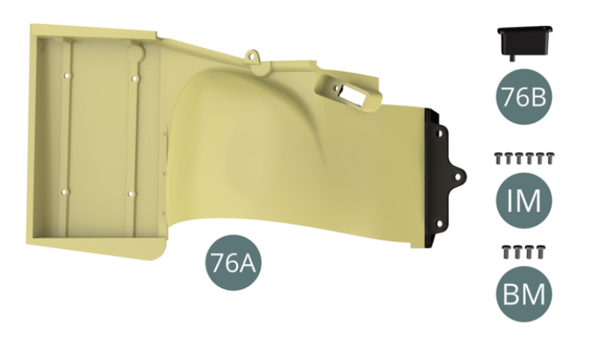
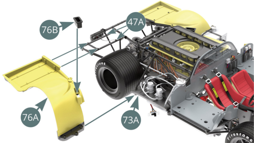
Kit 76
Parts of kit
- 76A Right rear wheel arch
- 76B Rear brake cooling bailer
- IM Screw M 1.7 x 3.5 mm (x 6)
- BM Screw M 2.0 x 4 mm (x 4)
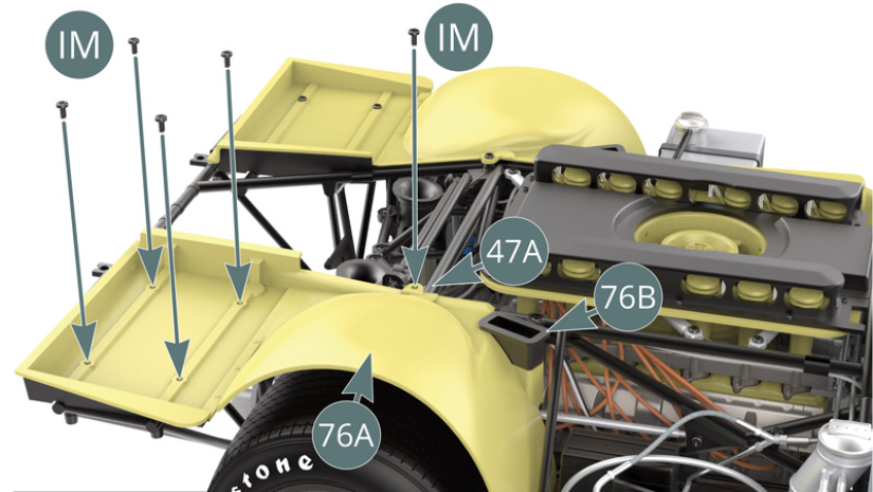
Step 1
Position the rear brake cooling bailer (76B) on the right rear wheel arch (76A). Position the right rear wheel arch (76A) on the upper frame (47A), placing its front support under the right side platform (73A). Secure the right rear wheel arch (76A) to the upper frame (47A) with five IM screws.
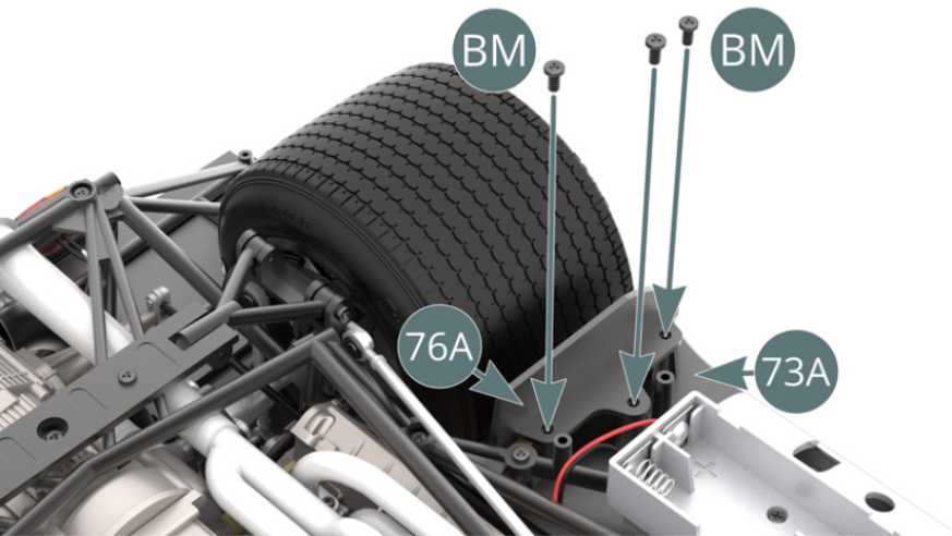
Step 2
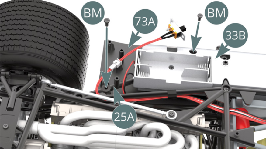
Flip the car over and attach the right rear wheel arch front bracket (76A) to the right side platform (73A) with three BM screws.
ASSEMBLY DIAGRAM
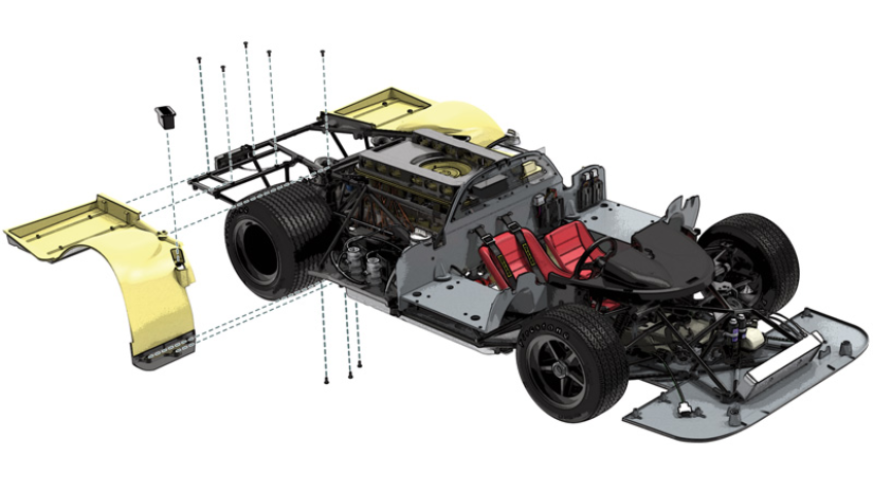
GENERAL VIEW