English
 français
 Deutsch
 español
 italiano
 português


Box 22
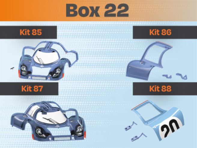
Kit 85
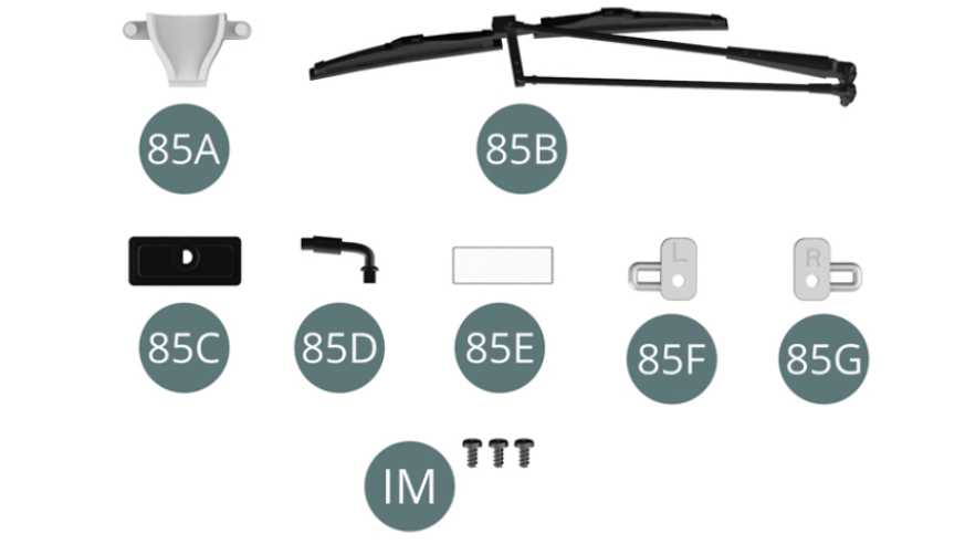
Parts of kit
- 85A Air intake
- 85B Windscreen wiper
- 85C Rear-view mirror shell
- 85D Rear-view mirror support
- 85E Rear-view mirror
- 85F Door lock, left
- 85G Door lock, right
- IM Screw M 1.7 x 3.5 mm (x 3)
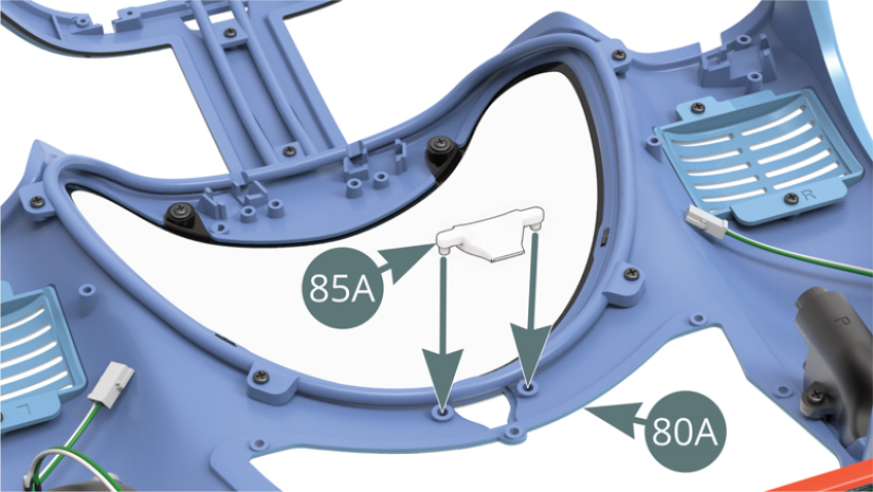
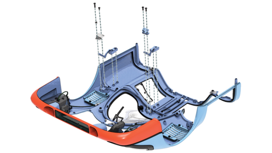
Step 1
Position the air intake (85A) below the body (80A). Position the right (85G) and left (85F) door locks to the body (80A) and secure with two IM screws.
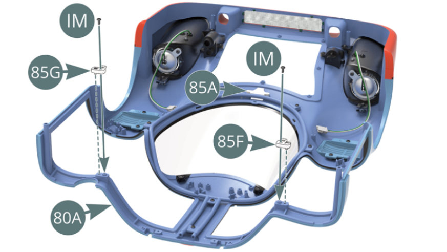
Step 2
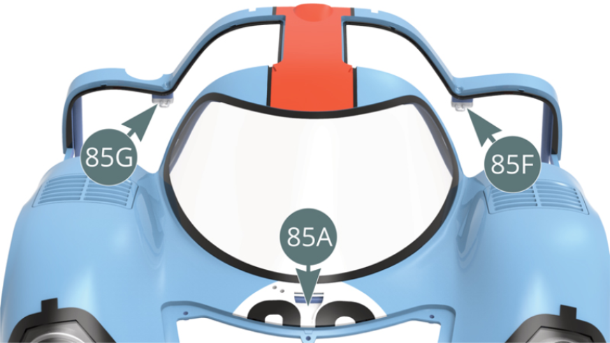
The right (85G) and left (85F) door locks are mounted on the body (80A).
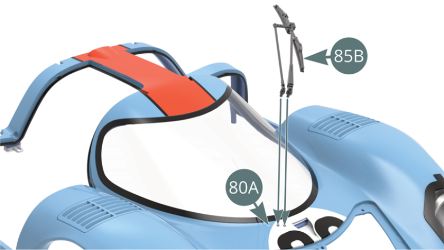
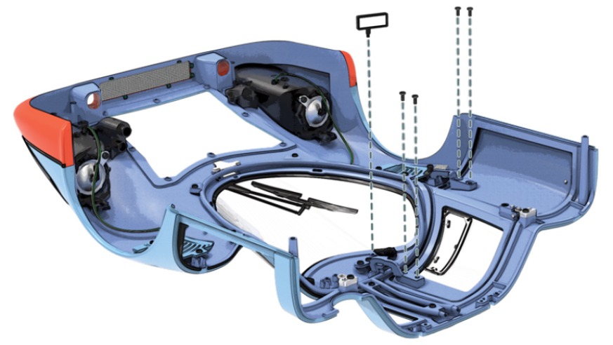
Position the wiper (85B) on the body (80A).
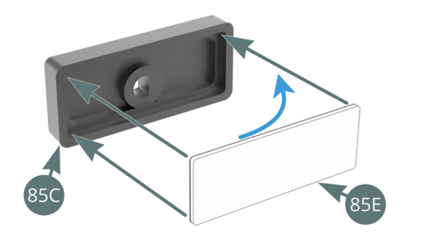
Step 3
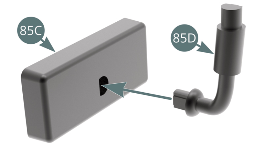
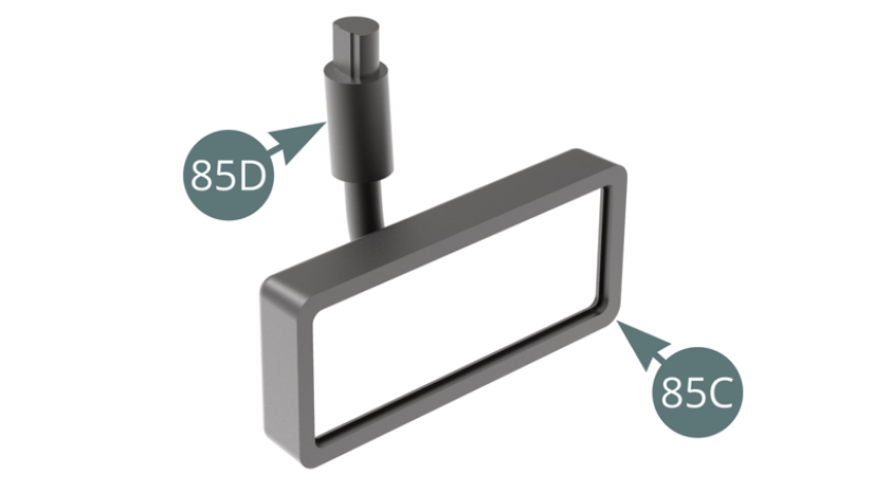
Remove the paper protector from the mirror (85E) and stick it inside the mirror shell (85C). Place the mirror support (85D) on the mirror shell (85C).
Step 4
Carefully put the assembled mirror aside for installation in the next step.
ASSEMBLY DIAGRAM
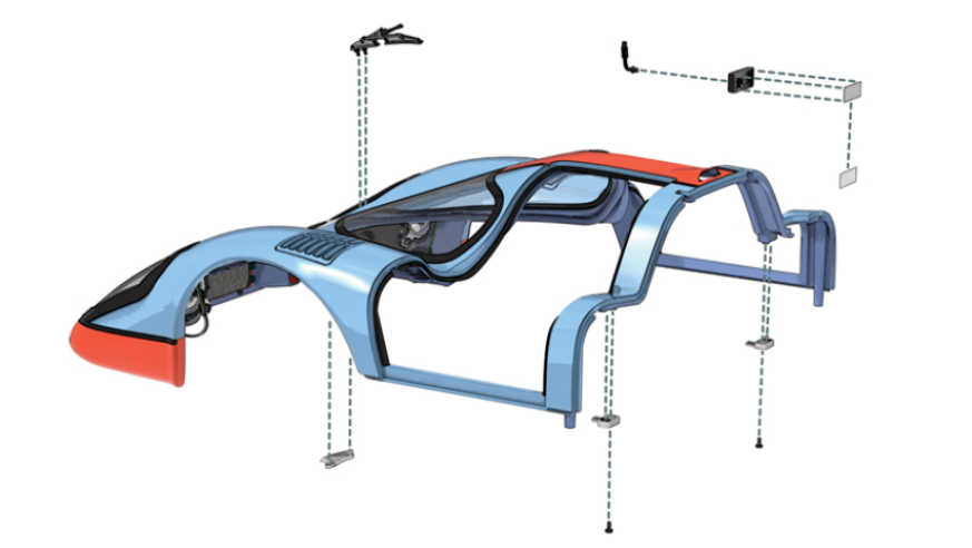
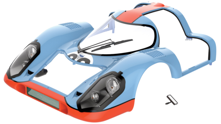
GENERAL VIEW
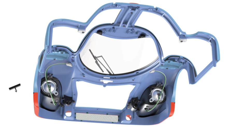
Kit 86
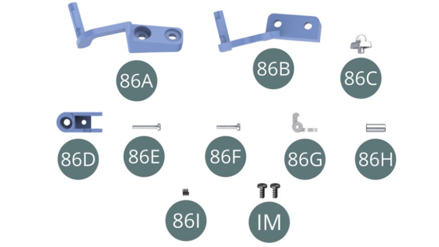
Parts of kit
- 86A Lower hinge
- 86B Top hinge
- 86C Door light
- 86D Lock
- 86E Pin (long)
- 86F Pin (short)
- 86G Latch
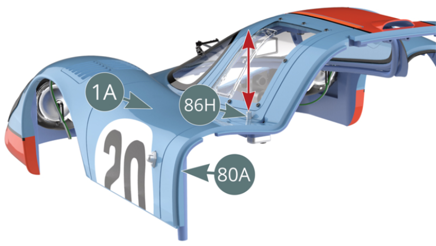
- 86H Release button
- 86I Spring
- IM Screw M 1.7 x 3.5 mm (x 2)
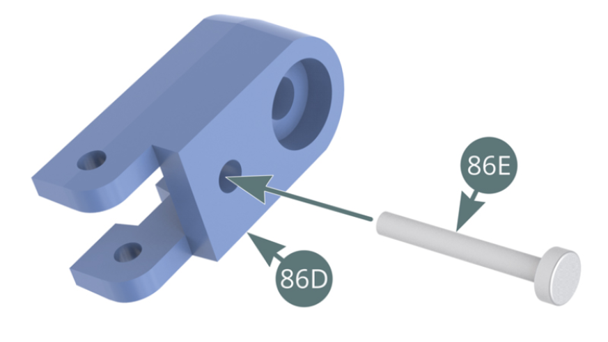
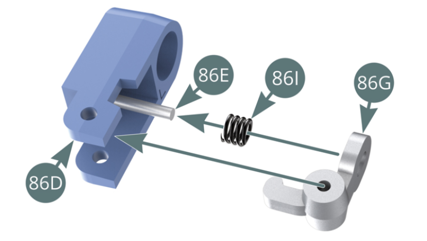
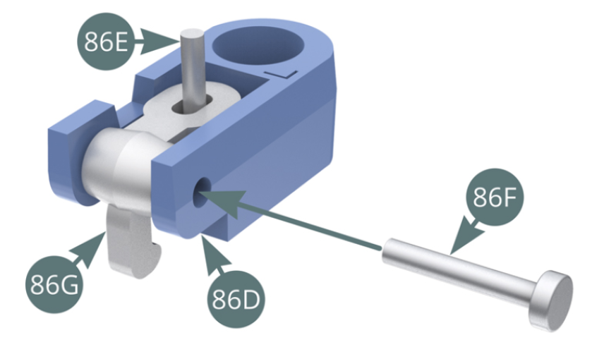
Step 1
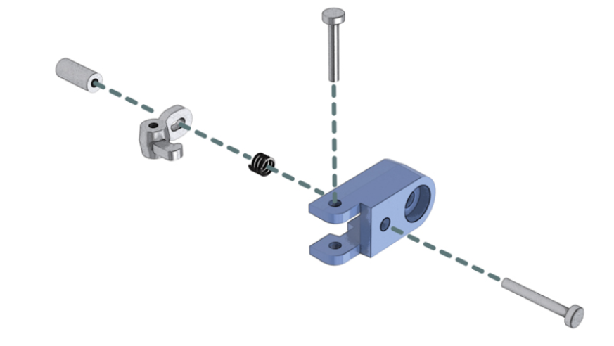
Insert the long pin (86E) into the locking body (86D). Position the spring (86I) and latch (86G) on the long pin (86E).
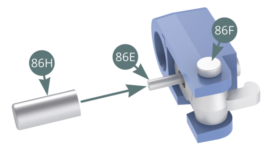
Step 2
Align the latch pin (86G) with the locks (86D), then insert the short pin (86F). Position the release button (86H) on the long pin (86E).
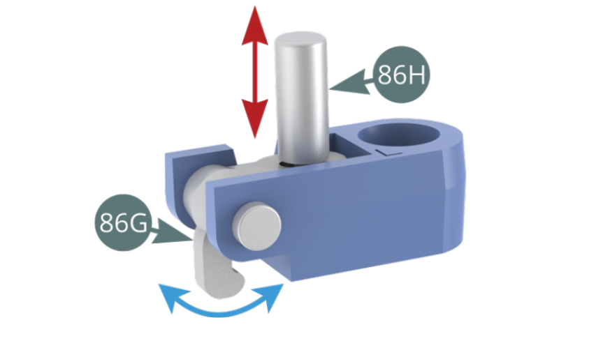
Step 3
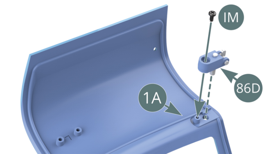
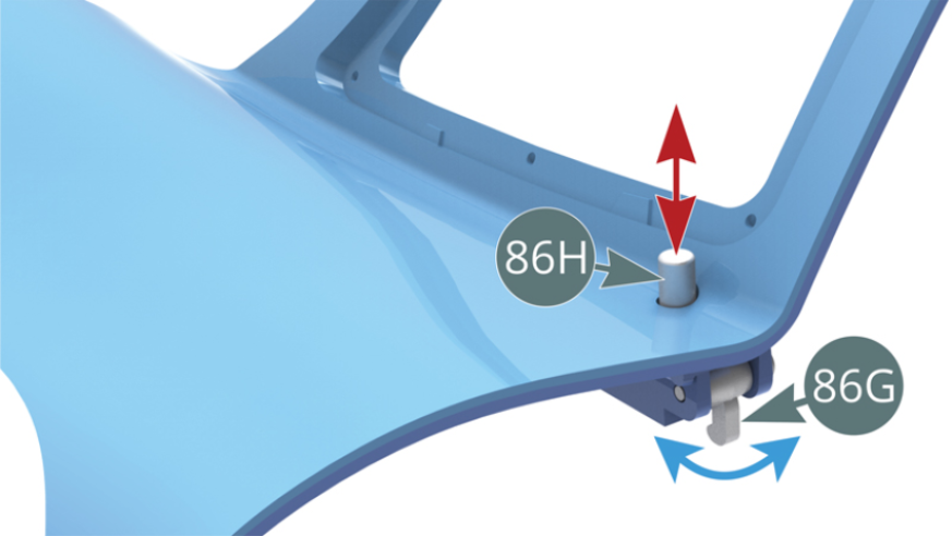
Press the release button (86H) to ensure that the latch (86G) swings out.
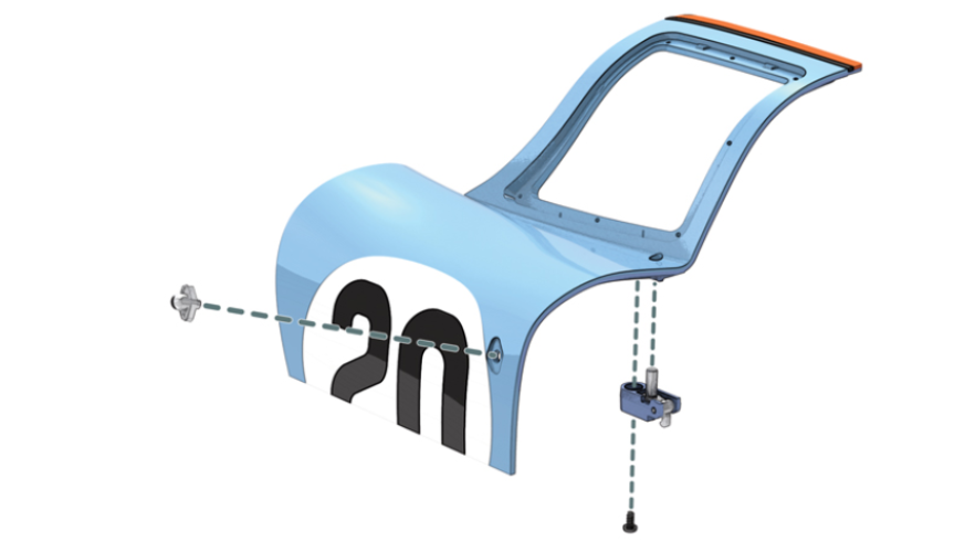
Position the lock assembly (86D) at the rear of the left door (1A) and secure with an IM.
Step 4
Press the release button (86H) again to ensure that the latch (86G) still swings out correctly.
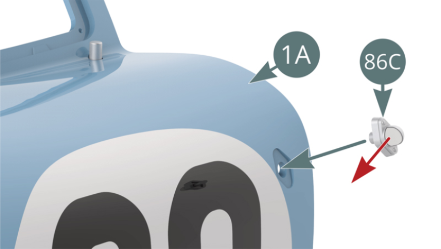
Position the door light (86C) on the left door (1A) ensuring that the light is pointing forward.
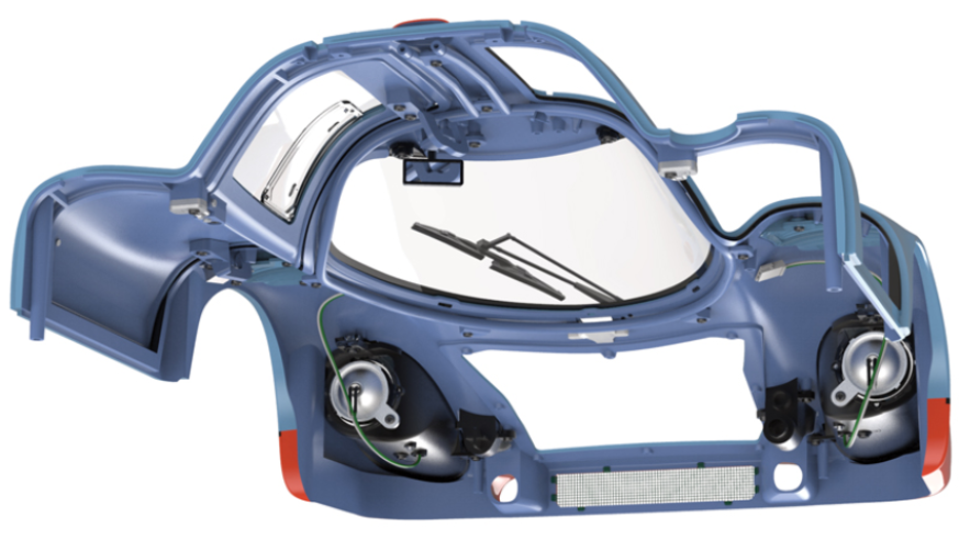
ASSEMBLY DIAGRAM
GENERAL VIEW
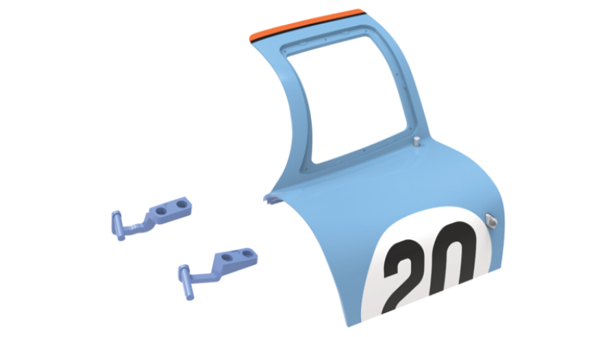
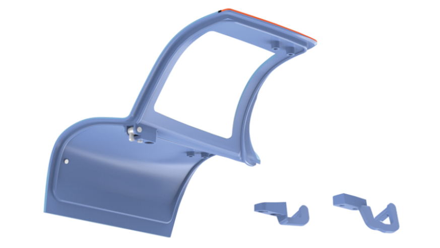
Kit 87
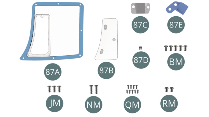
Parts of kit
- 87A Window
- 87B Ventilation window
- 87C Mounting tab
- 87D Spring
- 87E Mounting tab
- BM Screw M 2.0 x 4 mm (x 5)
- JM Screw M 2.0 x 5 mm (x 3)
- NM Screw M 2.0 x 7 mm (x 2)
- QM Screw M 1.2 x 3 mm (x 9)
- RM Screw M 2.0 x 3 mm (x 2)
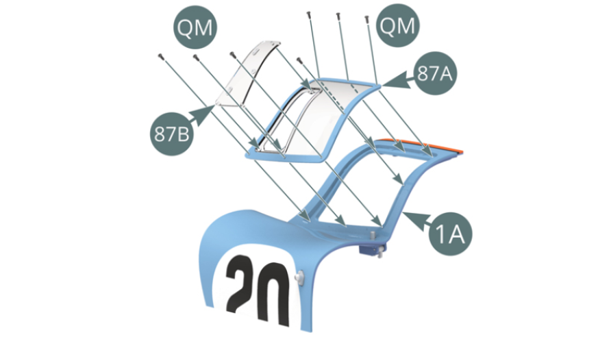
Step 1
Position the ventilation window (87B) on the window (87A) using its three lugs. Position the window (87A) on the left door (1A) and secure it with seven QM screws.
Step 2
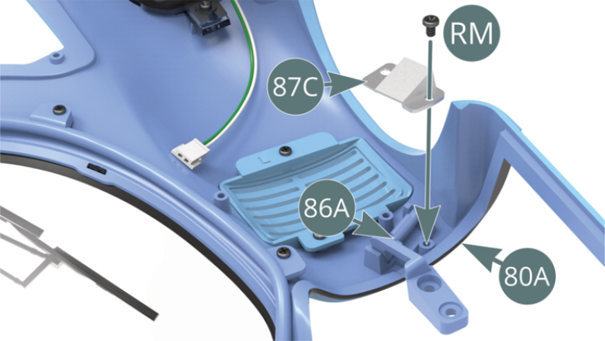
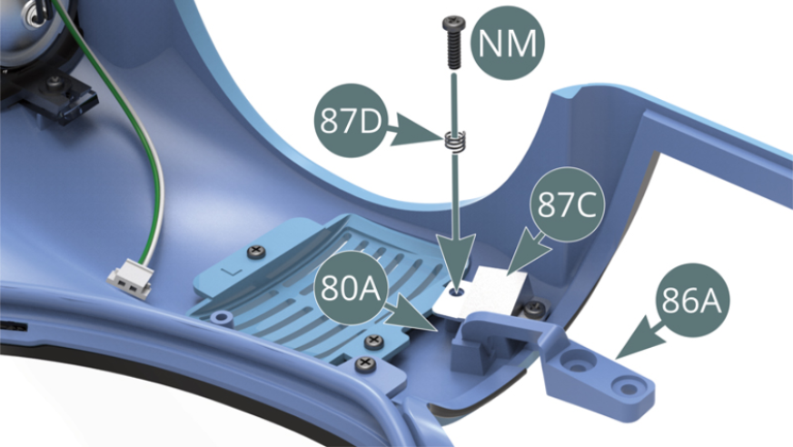
Position the lower hinge pin (86A) in the cradle slot on the body (80A), place the mounting tab (87C) on top and secure with an RM screw at one side. Secure the other side of the mounting tab (87C) to the body (80A) with an NM screw through the spring (87D). Do not overtighten the NM screw to allow the spring (87D) to compress.
Step 3
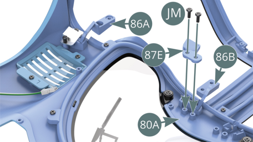
Position the top hinge pin (86B) in the cradle slot on the body (80A), place the mounting tab (87E) on top and secure with two JM screws.
Step 4
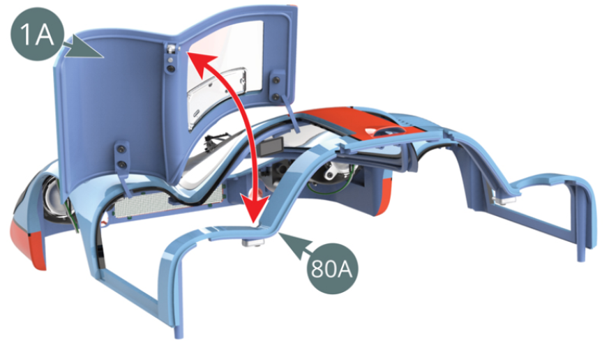
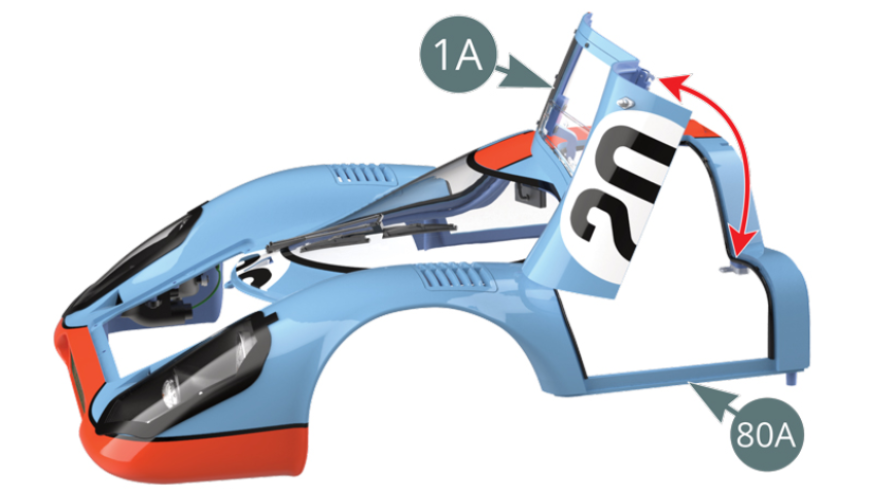
Position the left door (1A) onto the body (80A) and engage the latch (86G) into the lock (85F).
Insert the lower (86A) and top (86B) hinges into the left door (1A) and secure them with four BM screws.

Step 5
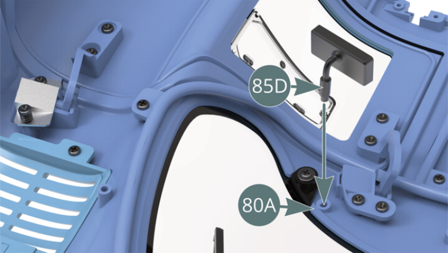
Attach the mirror with its support (85D) to the slot in the ceiling inside the body (80A). Press the release button (86H) to check that the left door (1A) opens correctly as detailed later on.
Step 6
Test the opening and closing of the left door (1A).
ASSEMBLY DIAGRAM
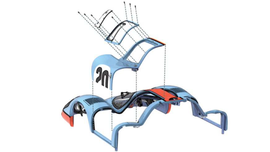
GENERAL VIEW
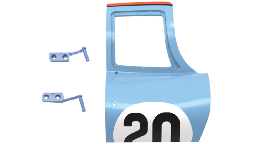
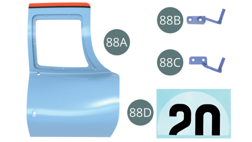
Kit 88
Parts of kit
- 88A Right door
- 88B Lower hinge
- 88C Top hinge
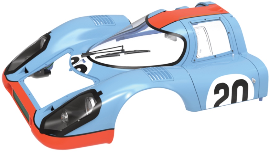
- 88D Decal (x 2)
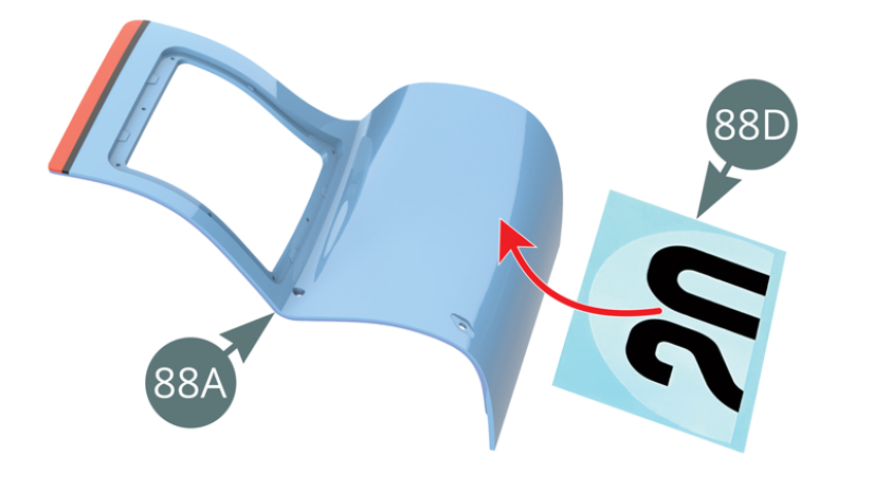
Step 1
Immerse the decal (88D) into water for 60 seconds, then carefully slide it onto the outside of the right door (88A).
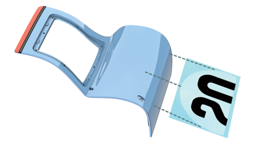
Step 2
Align and position the decal according to the following illustration. Wait 3 minutes for it to set, then gently smooth it with a soft cotton pad.

ASSEMBLY DIAGRAM
GENERAL VIEW