English
 français
 Deutsch
 español
 italiano
 português


Box 23

Kit 89
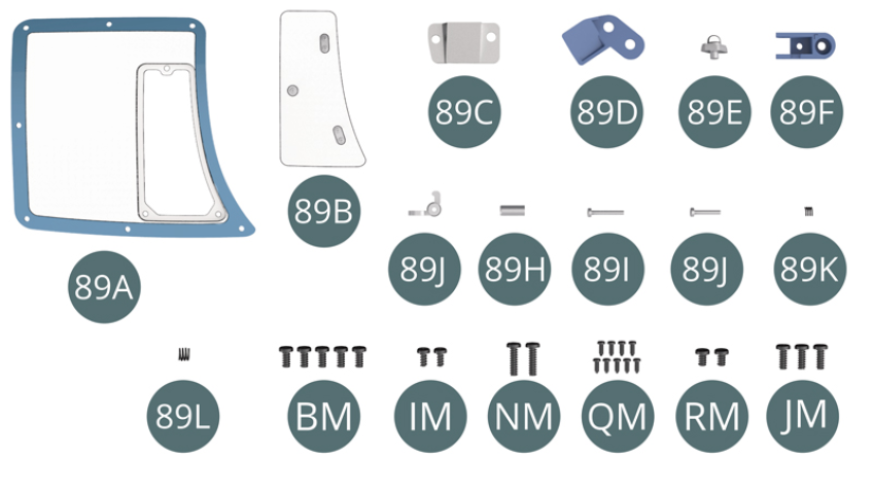
Parts of kit
- 89A Window
- 89B Ventilation window
- 89C Bracket
- 89D Bracket
- 89E Door light
- 89F Lock
- 89G Door latch
- 89H Release button
- 89I Pin (long)
- 89J Pin (short)
- 89K Spring (small)
- 89L Spring (large)
- BM Screw M 2.0 x 4 mm (x 5)
- IM Screw M 1.7 x 3.5 mm (x 2)
- NM Screw M 2.0 x 7 mm (x 2)
- QM Screw M 1.2 x 3 mm (x 9)
- RM Screw M 2.0 x 3 mm (x 2)
- JM Screw M 2.0 x 5 mm (x 3)
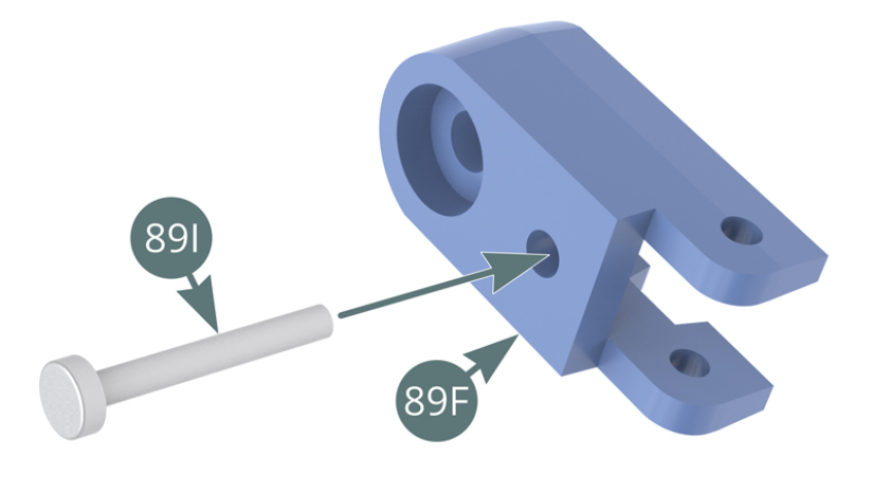
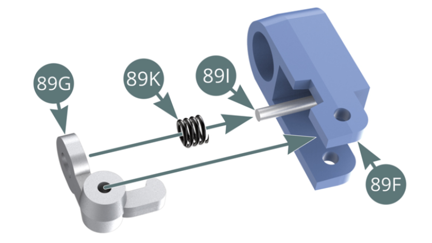
Step 1
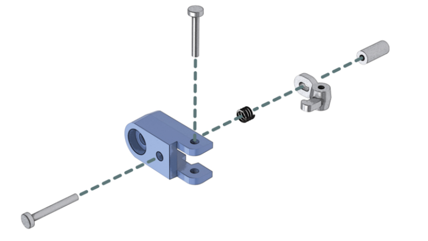
Insert the long pin (89I) into the lock housing (89F). Position the small spring (89K) and latch (89G) onto the long pin (89I).
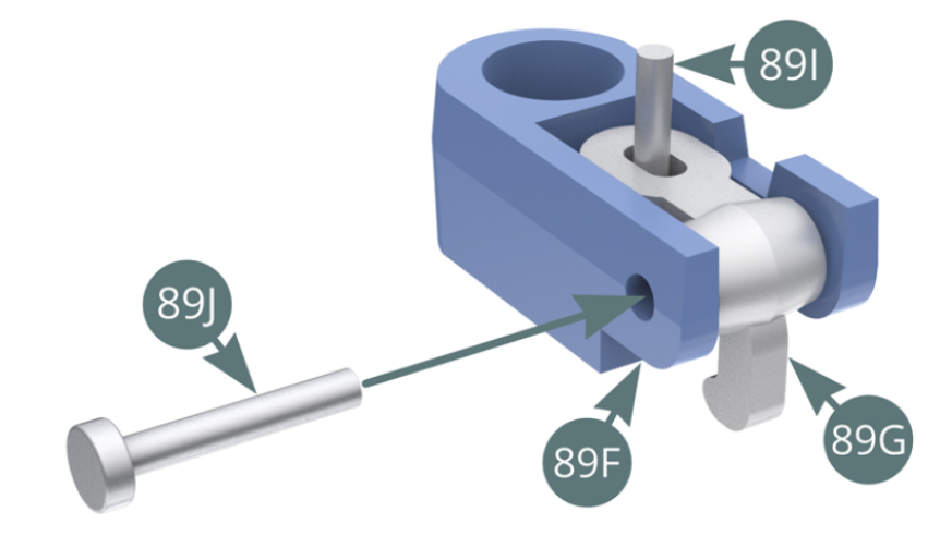
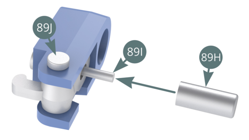
Step 2
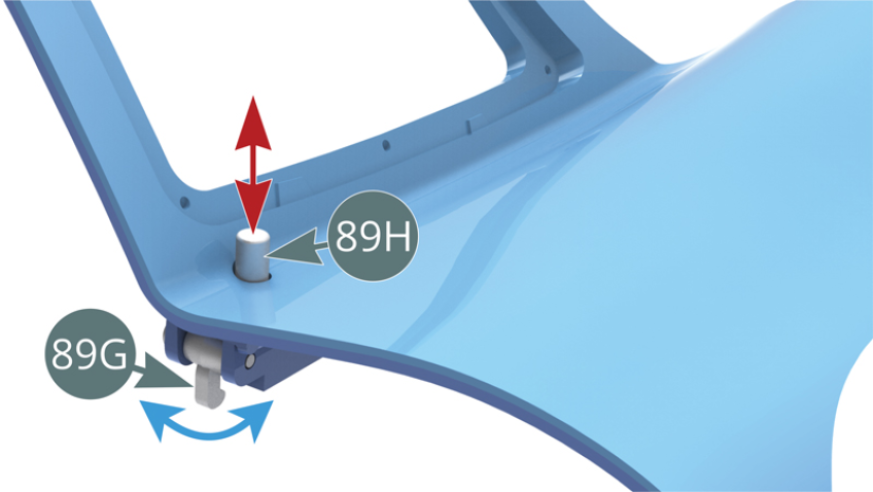
Align the latch axis (89G) with the lock axis (89F), then insert the short pin (89J). Position the release button (89H) onto the long pin (89I).
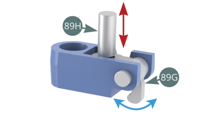
Step 3
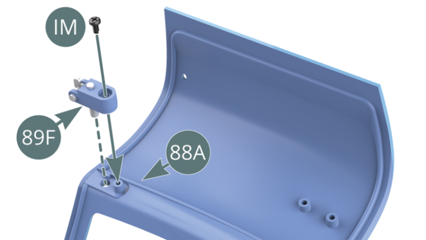
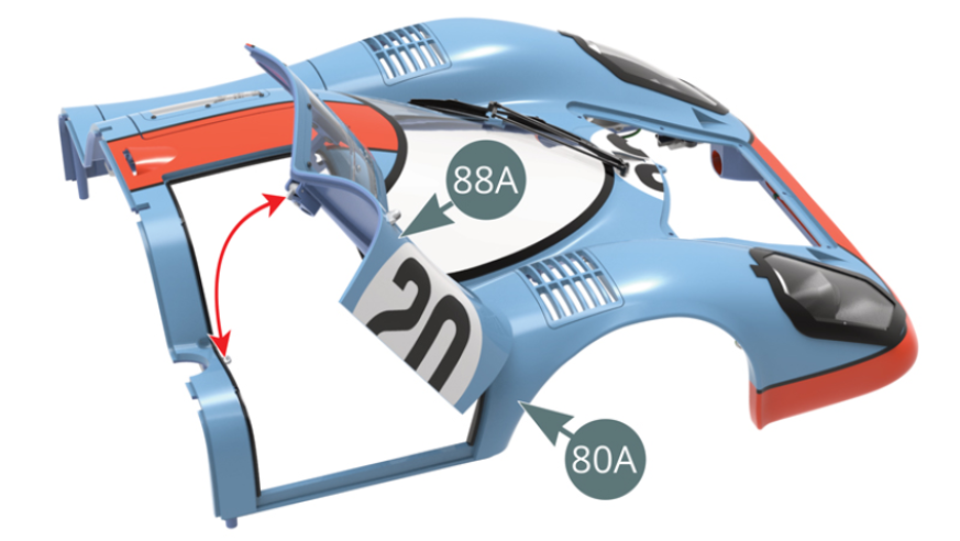
Press the release button (89H) to check that the door latch (89G) swings out. Position the lock assembly (89F) on the rear of the right door (88A) and secure with an IM screw.
Step 4
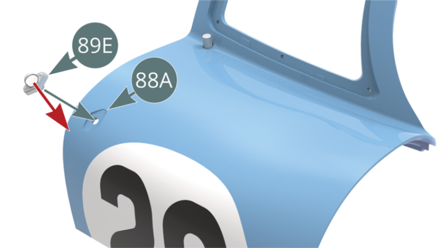
Press the release button (89H) again to check that the latch (89G) still swings out correctly. Position the door light (89E) on the right hand door (88A) ensuring the light is pointed forward.
Step 5
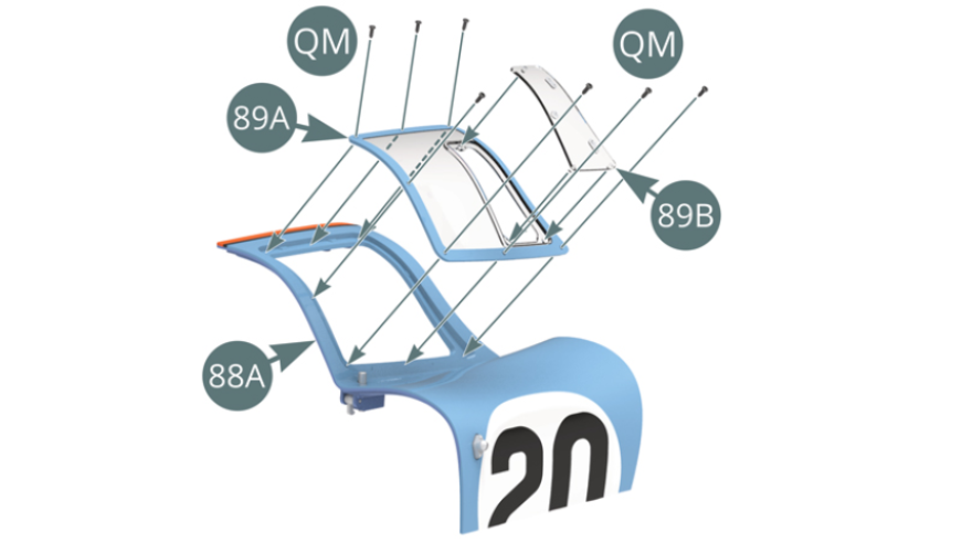
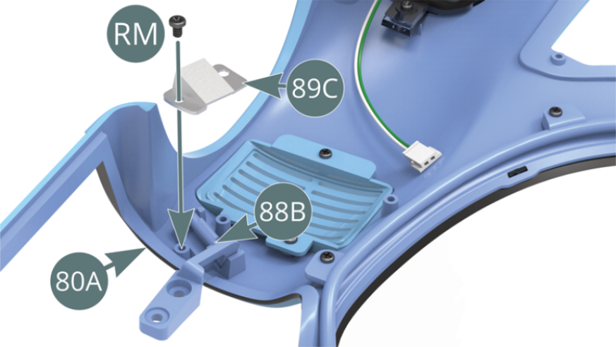
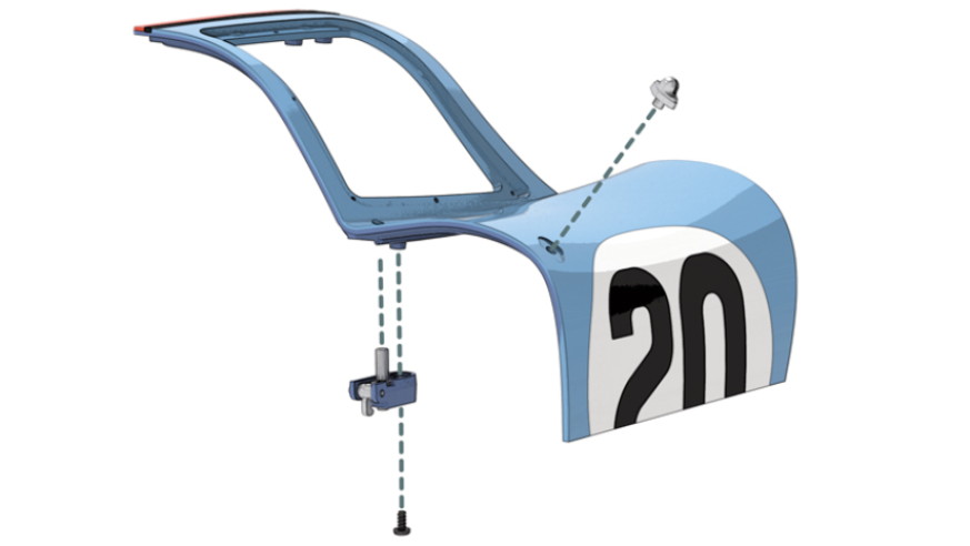
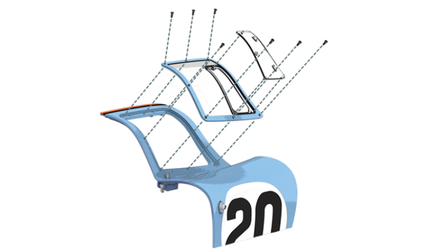
Position the ventilation window (89B) on the window (89A) using its three lugs. Position the window (89A) on the right side door (88A) and secure with seven QM screws. Position the lower hinge axis (88B) into the slot that is located in the body (80A), place the bracket (89C) on top and secure with an RM screw on one side.
Step 6
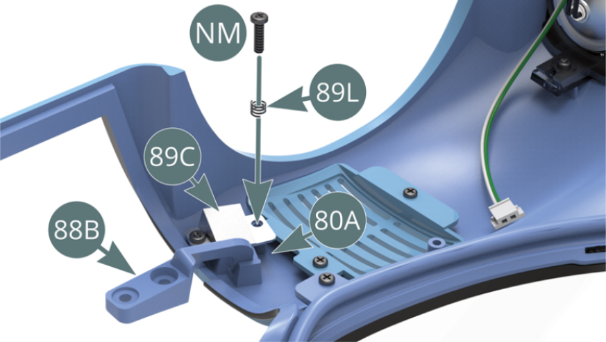
Attach the other side of the bracket (89C) to the body (80A) with an NM screw passed through the large spring (89L). Do not over tighten the NM screw to allow the spring (89L) to compress.
Step 7
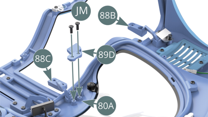
Position the upper hinge axis (88C) in the cradle slot provided on the body (80A), place the bracket (89D) on top and secure with two JM screws.
Step 8
Position the right side door (88A) to the body (80A) and engage the latch (89G) in the door lock (85G). Position the lower (88B) and top (88C) hinges to the right door (88A) and secure with four BM screws.

Step 9
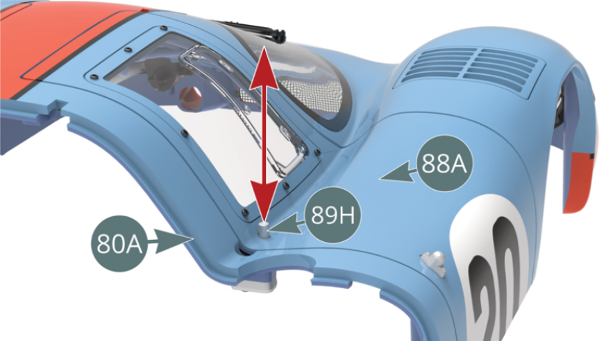
Press the release button (89H) to check that the right door (88A) opens correctly as shown below.
Step 10
Test opening and closing the right side door (88A).
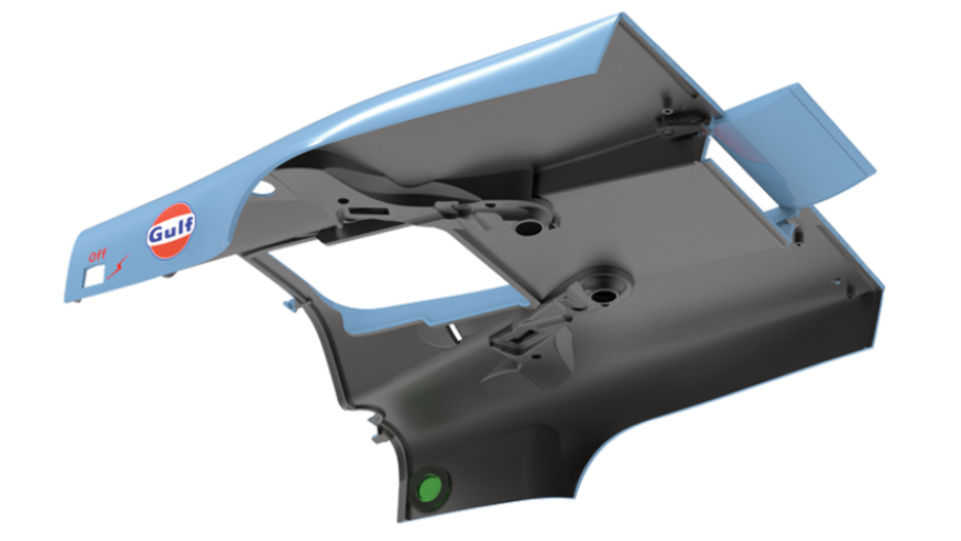
ASSEMBLY DIAGRAM
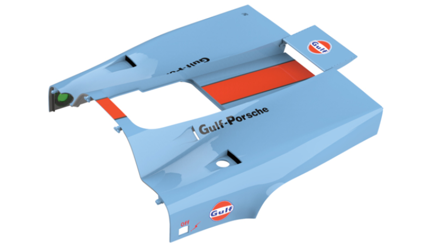
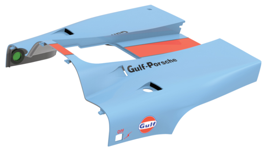
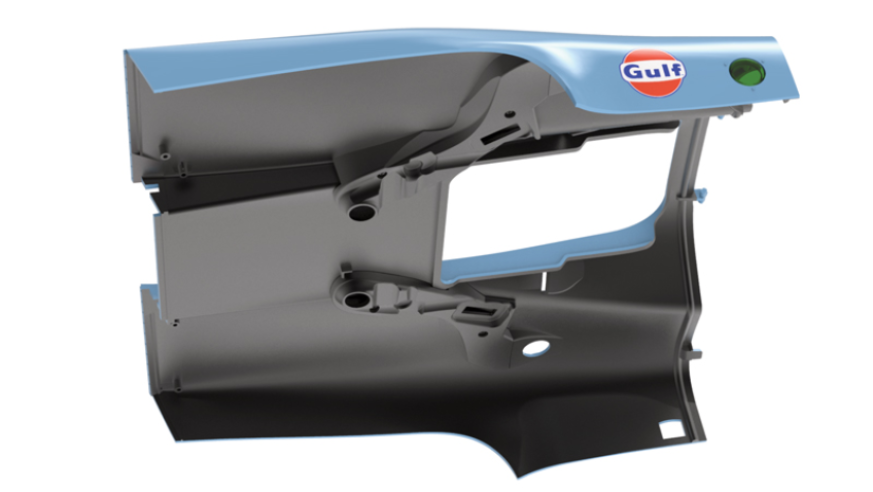
GENERAL VIEW
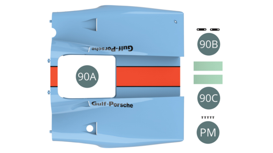
Kit 90
Parts of kit
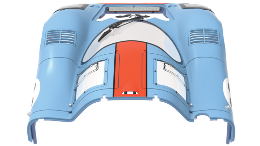
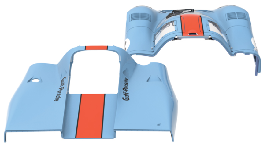
- 90A Rear bonnet
- 90B Hinge bracket (x 2)
- 90C Clear tape
- PM Screw M 2.0 x 4 mm (x 5)
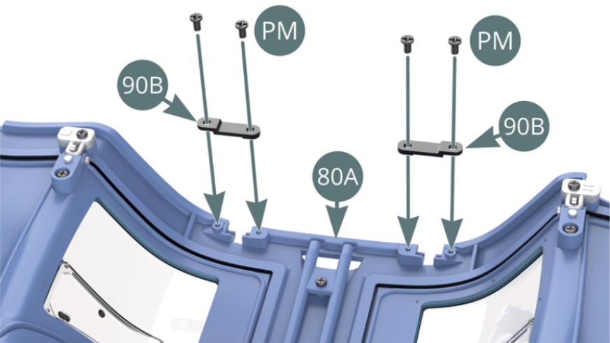
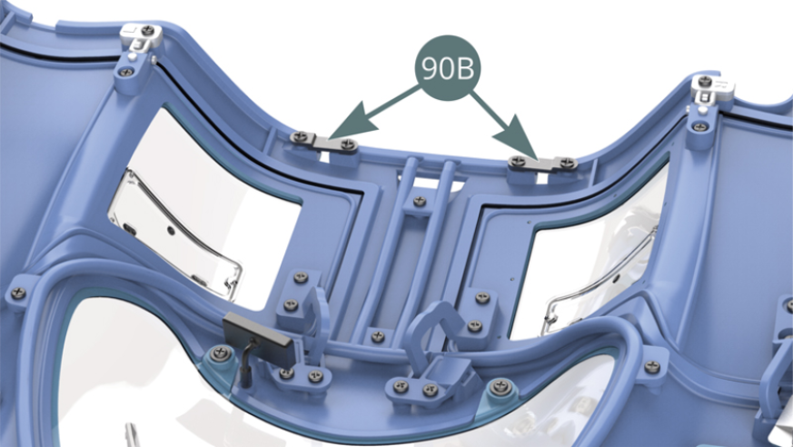
Step 1
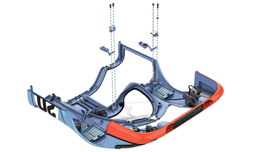
Position the two hinge brackets (90B) on the supports at the rear of the body (80A) and secure with four PM screws.
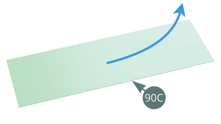
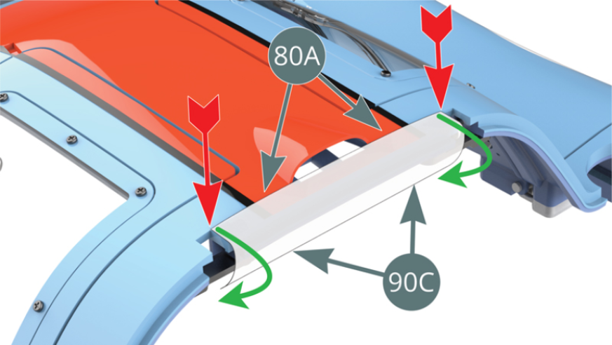
Step 2
Remove the backing paper from the clear tape (90C) and apply it by wrapping it around the rear edge of the bodywork (80A). The clear tape (90C) will serve to protect the paint from scratching during testing of the rear bonnet (90A).
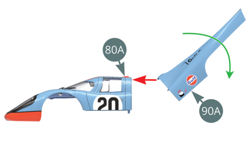
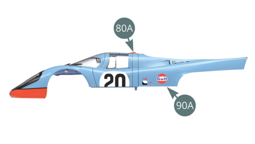
Step 3
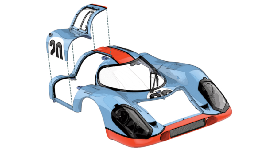
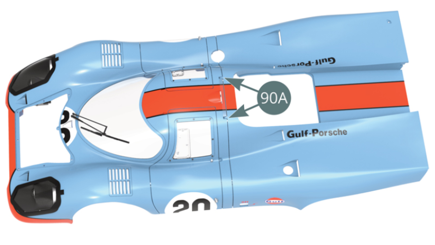
Raise the rear bonnet (90A) to an angle of 45 degrees and while keeping this angle, bring it forward (red arrow) to insert its two hinges into the body hinge brackets (80A). Once it is inserted into the rear of the body, swing the rear bonnet to its horizontal position (green arrow, illustrations opposite and below).
Step 4
After testing the joint, remove the rear cover (90A) by performing the operation in reverse order (lift it at 45 degrees and then pulling it apart horizontally) for its re-assembly.
ASSEMBLY DIAGRAM

GENERAL VIEW

Kit 91
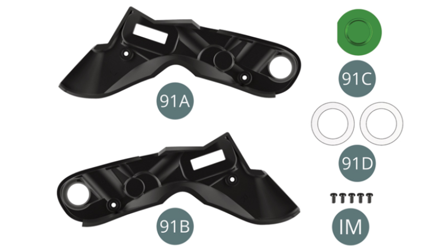
Parts of kit
- 91A Left air duct
- 91B Right air duct
- 91C Clear cap
- 91D Double-sided circular tape
- IM Screw M 1.7 x 3.5 mm (x 5)
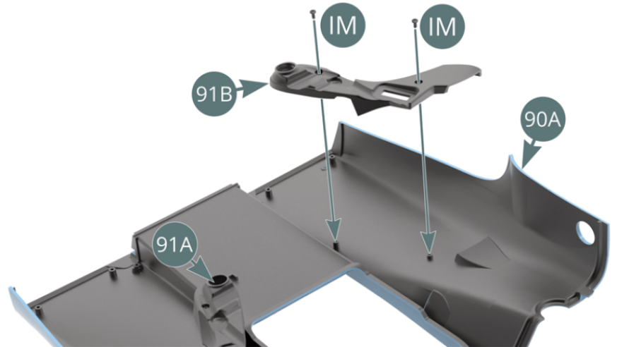
Step 1
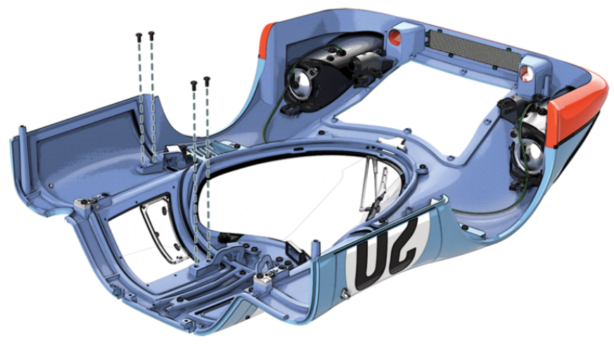
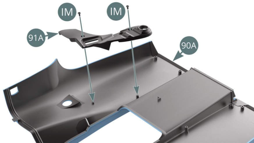
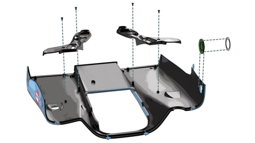
Position the left air duct (91A) on the inside of the rear bonnet (90A) and secure with two IM screws. Position the right air duct (91B) on the inside of the rear bonnet (90A) and secure with two IM screws.
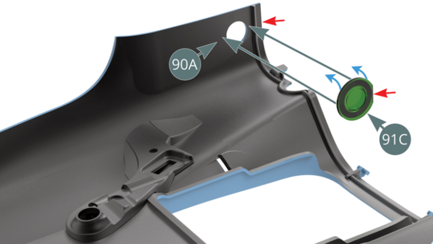
Step 2
Remove the circular double-sided tape (91D) from its paper backing and affix it around the protruding part of the clear cap (91C). Detach the paper backing from the double-sided tape that is attached to the clear cap (91C) - blue arrows - and stick it into the opening on the inner left side of the rear bonnet (90A). Orient the right side of the clear cap (91C) as indicated by the red arrows.

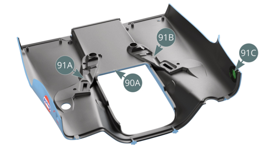
Step 3
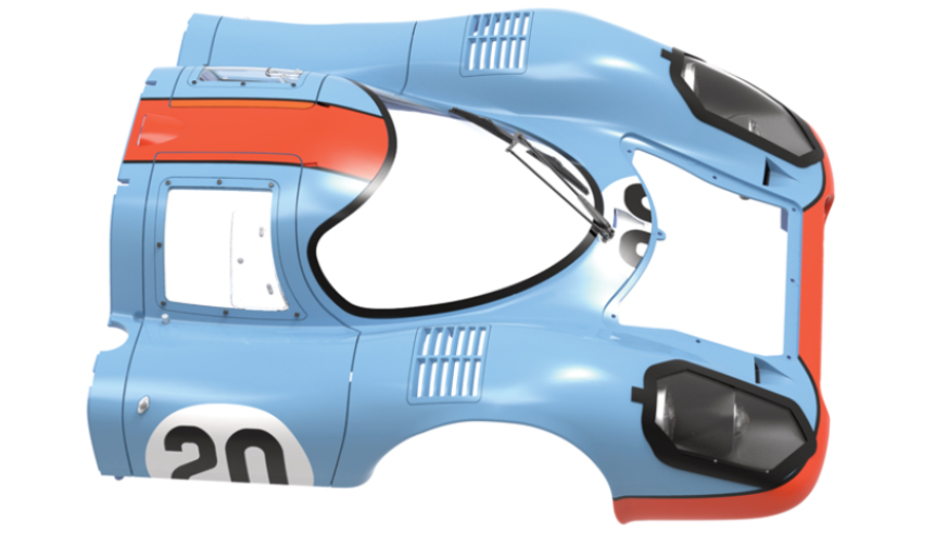
Left (91A) and right (91B) air ducts as well as the clear cap (91C) are attached to the rear bonnet (90A).
ASSEMBLY DIAGRAM
GENERAL VIEW
Kit 92
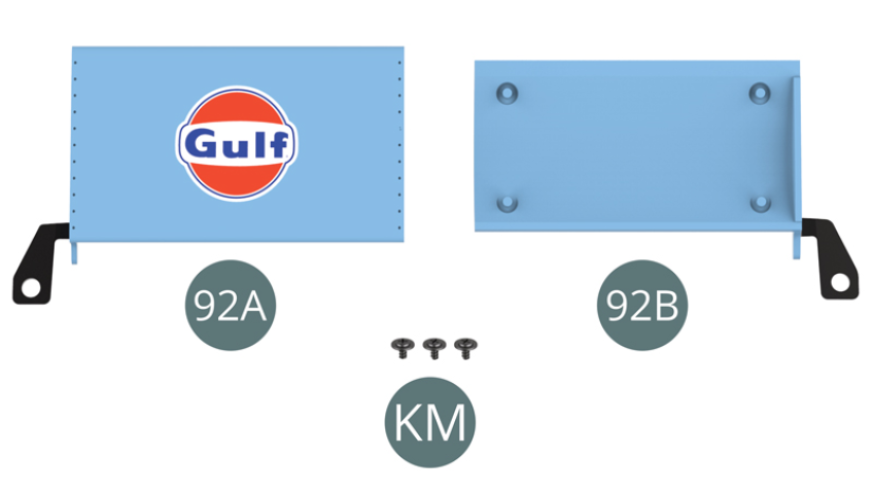
Parts of kit
- 92A Top centre spoiler
- 92B Bottom centre spoiler
- KM Screw M 1.7 x 3 x 5 mm (x 3)
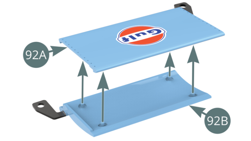
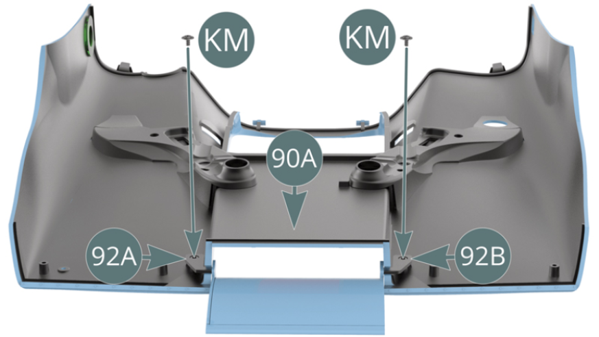
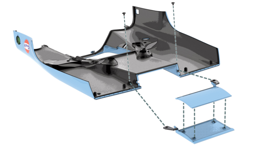
Step 1
Assemble the top (92A) and bottom (92B) of the centre spoiler. Place the centre spoiler assembly - top (92A) and bottom (92B) - onto the rear bonnet (90A).

Step 2
Attach the centre spoiler assembly - top (92A) and bottom (92B) - to the rear bonnet (90A) with two KM screws.
ASSEMBLY DIAGRAM
GENERAL VIEW