English
 français
 Deutsch
 español
 italiano
 português


Box 24

Kit 93
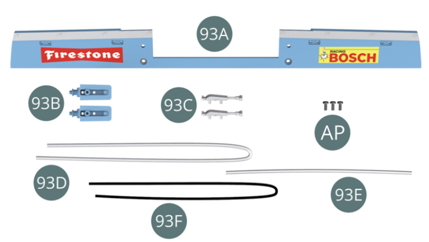
Parts of kit
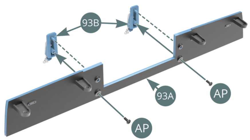
- 93A Rear bonnet panel
- 93B Lock support (x 2)
- 93C Lock (x 2)
- 93D Fuel hose (long)
- 93E Fuel hose (short)
- 93F Fuel vent hose
- Screw AP M 1.7 x 4 mm (x 3)
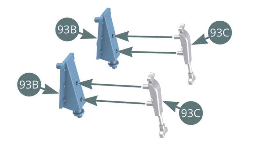
Step 1
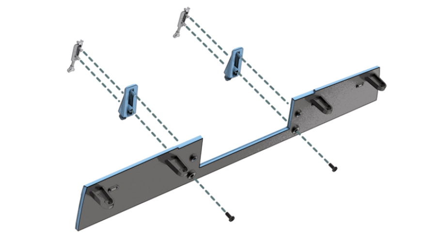
Position the two locks (93C) on the two lock supports (93B). Position the two lock supports (93B) on the rear bonnet panel (93A) and secure them with two AP screws.
Step 2
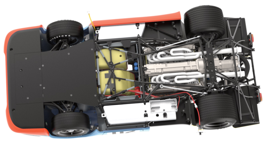
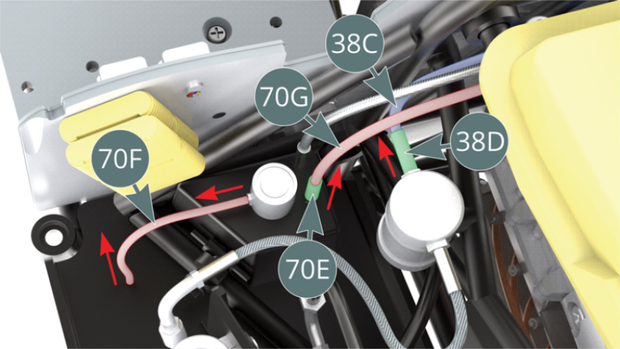
On the left side of the chassis, detach the fuel hose (70F) - highlighted in red. Remove the shielded fuel line (70G) - highlighted in red - by carefully pulling it upwards with its fitting (70E). Remove the fuel hose (38C) and its connector (38D).
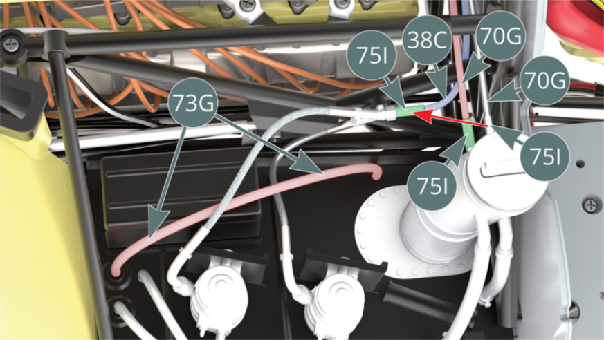
On the right side of the chassis, detach the fuel hose (73G) - highlighted in red. Remove the shielded fuel line (70G) - highlighted in red - with its connector (75I). Remove the fuel hose (38C) - highlighted in blue - and its connector (75I) and replace it with the shielded fuel line (70G) with its connector (75I) that have just been removed.
Step 3
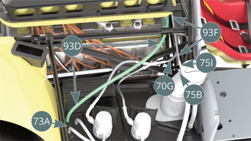
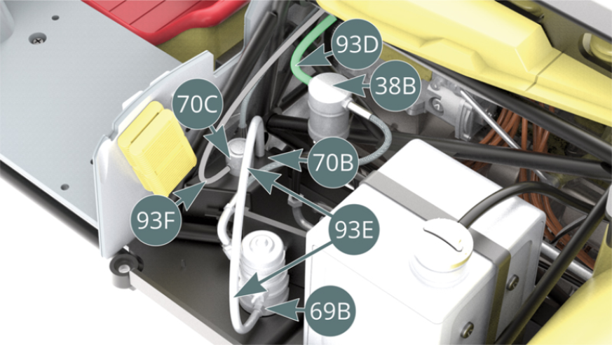
After reconnecting the shielded fuel line (70G) as described in the previous step, fit the fuel hose - long (93D) to the nozzle located on the right side platform (73A), then point the free end towards the other side of the chassis, sliding it along the front of the engine. Attach the fuel breather pipe (93F) with connector (75I) to one of the two nozzles on the fuel filler neck (75B), then point the free end towards the other side of the chassis, sliding it along the front of the engine.
Step 4
Return to the left side of the chassis and fit the fuel hose - long (93D) to the fuel filter (38B), then fit the fuel vent tube (93F) to the nozzle on the fuel cap (70C). Attach the fuel hose - short (93E) to the fuel manifold (70B) and nozzle of the fuel pump (69B).
Step 5
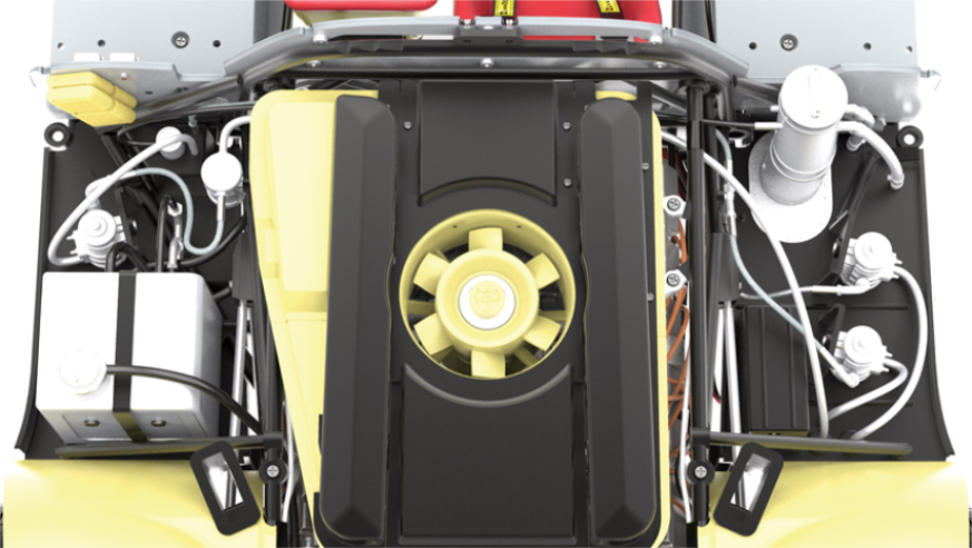
General layout of fuel hoses
ASSEMBLY DIAGRAM
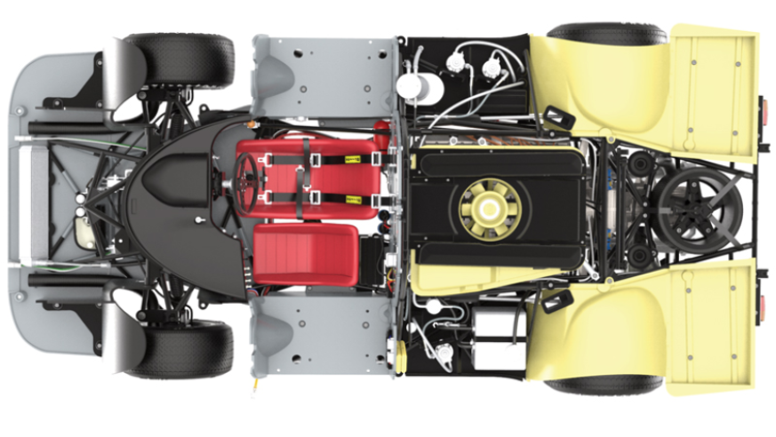
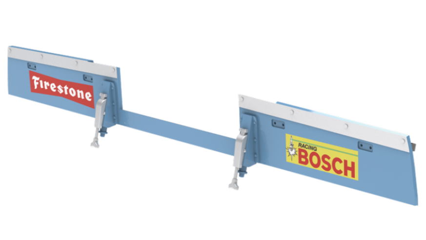
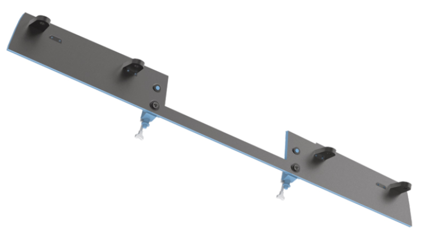
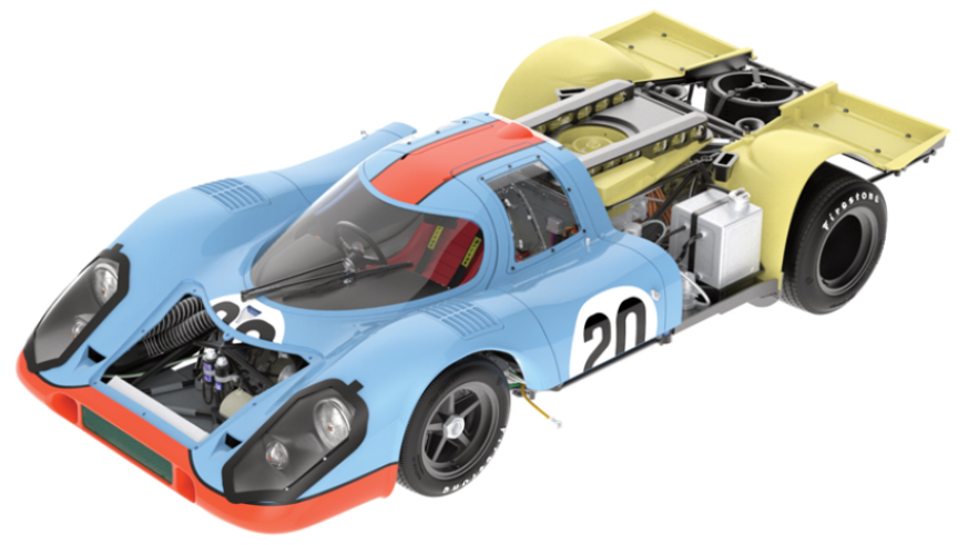
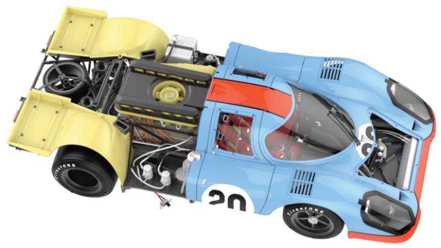
GENERAL VIEW
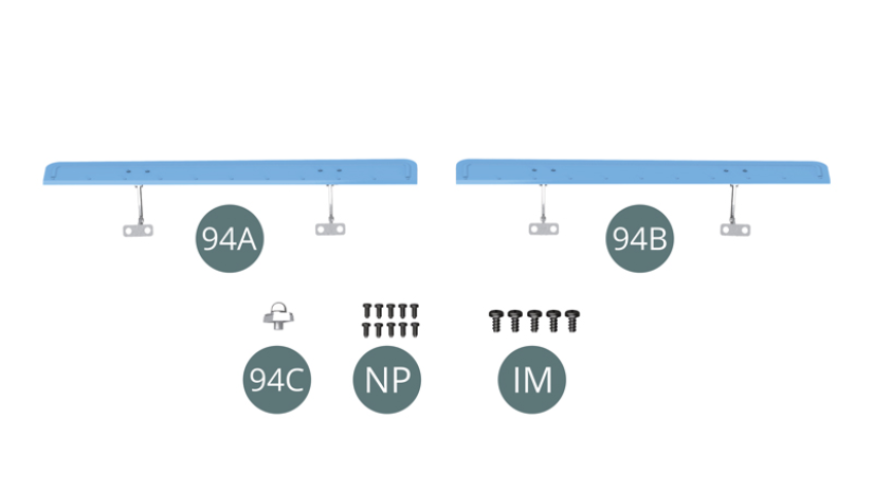
Kit 94
Parts of kit
- 94A Left side spoiler (L)
- 94B Right side spoiler (R)
- 94C Rear bonnet light
- Screw NP M 1.2 x 2.5 mm (x 10)
- Screw IM M 1.7 x 3.5 mm (x 5)
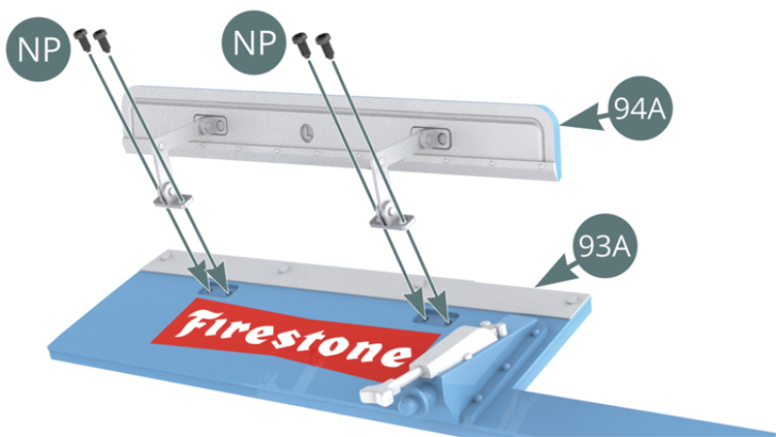
Step 1
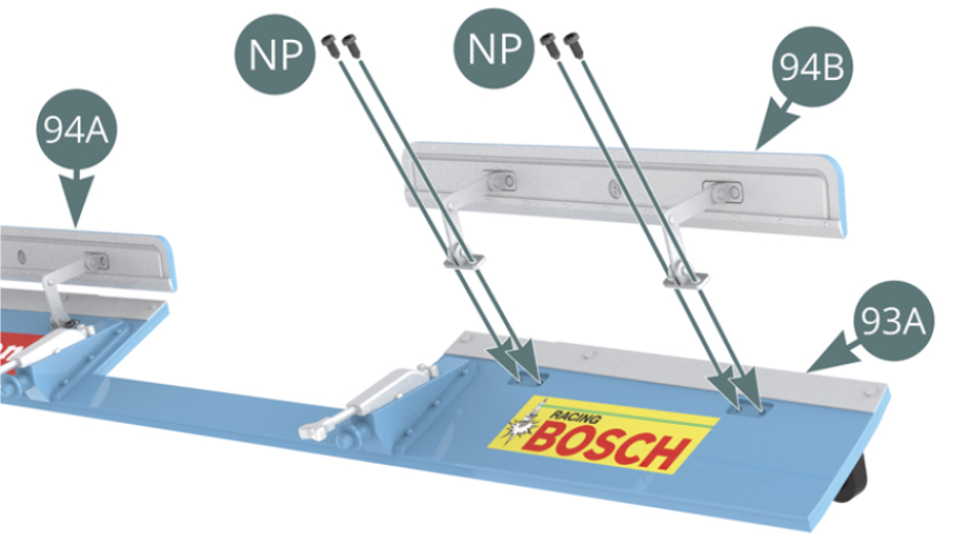
Position the left spoiler (94A) on the rear bonnet panel (93A) and secure with four NP screws.
Position the right spoiler (94B) on the rear bonnet panel (93A) and secure with four NP screws.
Step 2
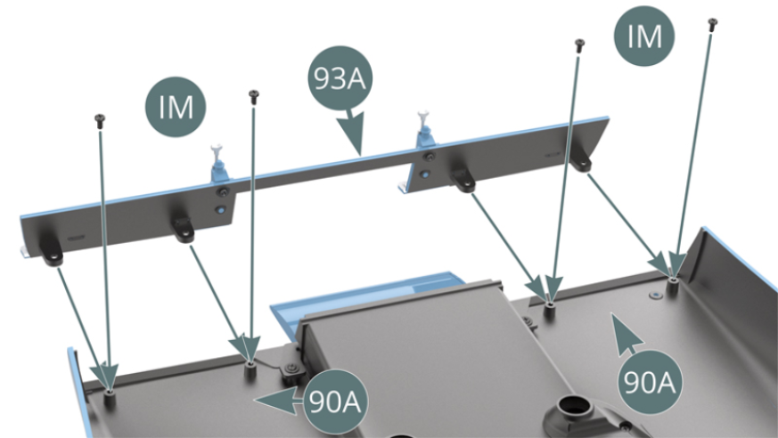
Position the rear bonnet panel (93A) on the rear bonnet (90A) and secure with four IM screws.
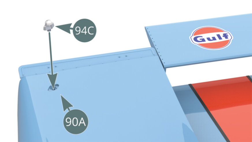
Position the light (94C) above the right side of the rear bonnet. Position the white glass of the rear bonnet light towards the front of the car.
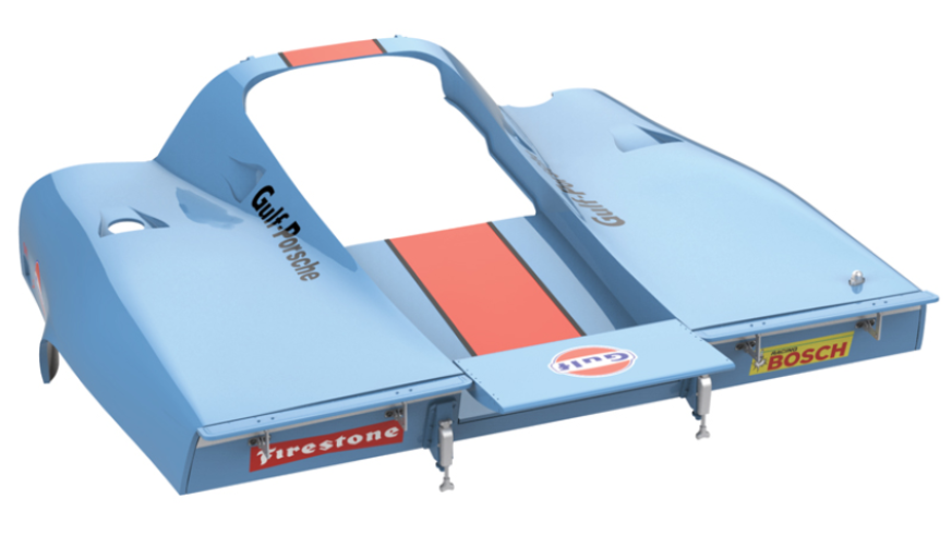
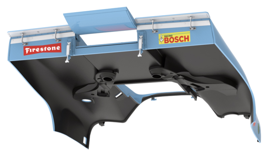
ASSEMBLY DIAGRAM
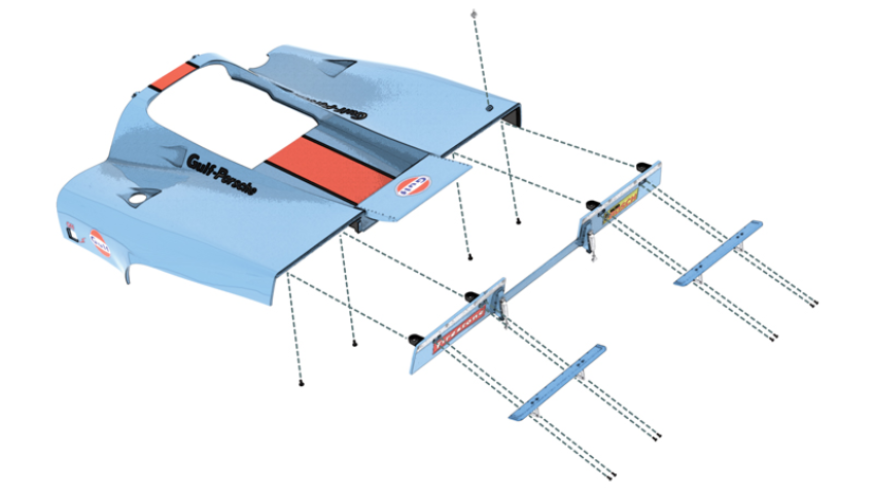
GENERAL VIEW
Kit 95
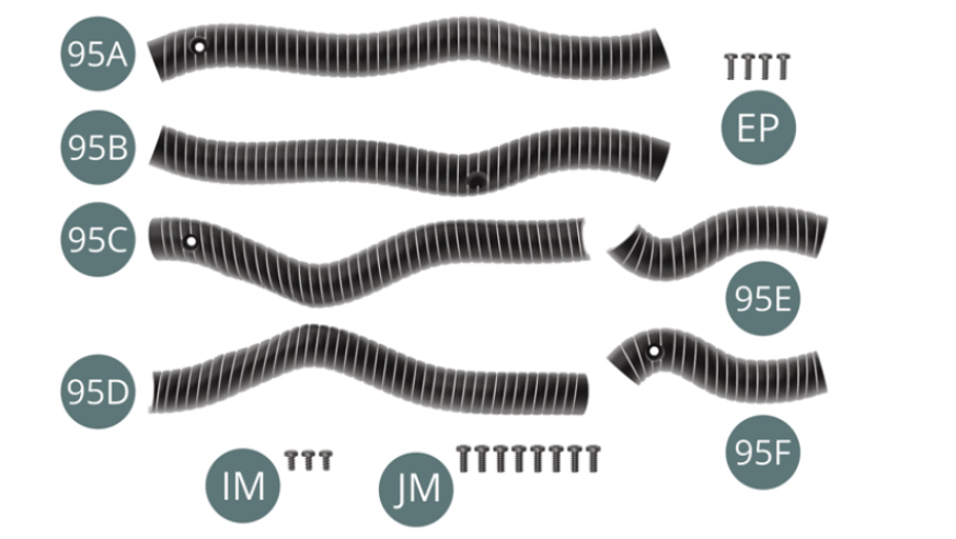
Parts of kit
- 95A Left half ventilation duct
- 95B Left half ventilation duct
- 95C Right half ventilation duct
- 95D Right half ventilation duct
- 95E Right half ventilation duct
- 95F Right half ventilation duct
- Screw EP M 1.7 x 5 mm (x 4)
- Screw IM M 1.7 x 3.5 mm (x 3)
- Screw JM M 2.0 x 5 mm (x 8)
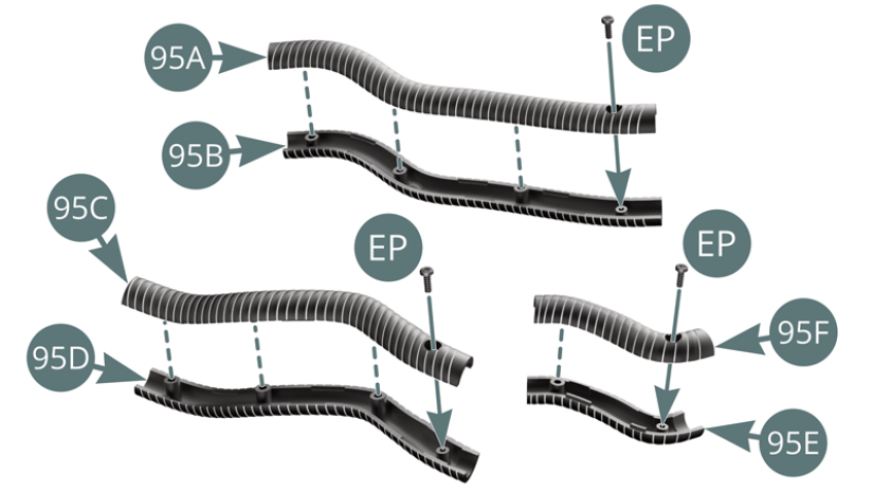
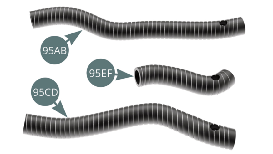
Step 1
Assemble the half-duct units (95A&95B) and secure them together with an EP screw to form the left ventilation duct (95AB) - top illustration. Assemble the half-duct units (95C&95D) and secure them together with an EP screw to form the right ventilation duct (95CD) - illustration above left. Assemble the half-duct units (95E&95F) and secure them together with an EP screw to form the right vent duct (95EF) - illustration above right.
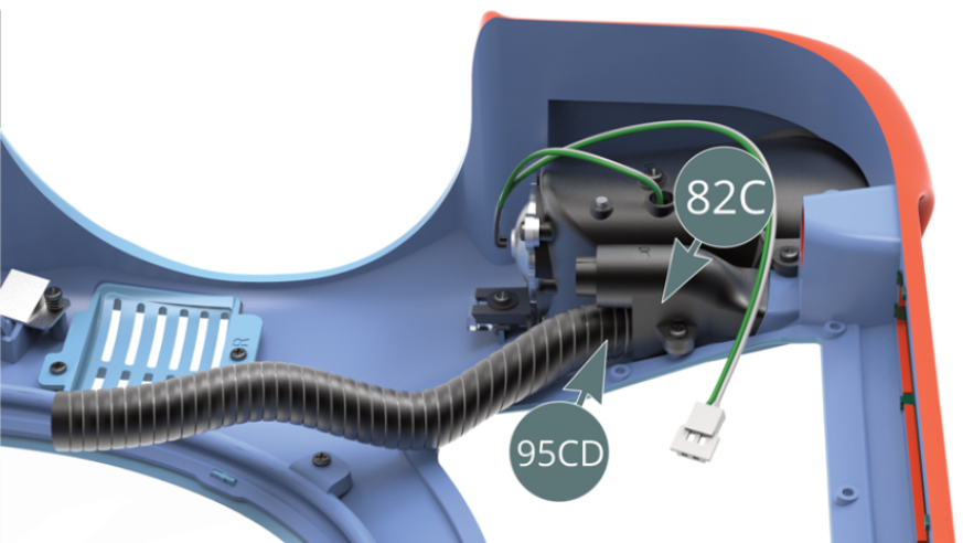
Step 2
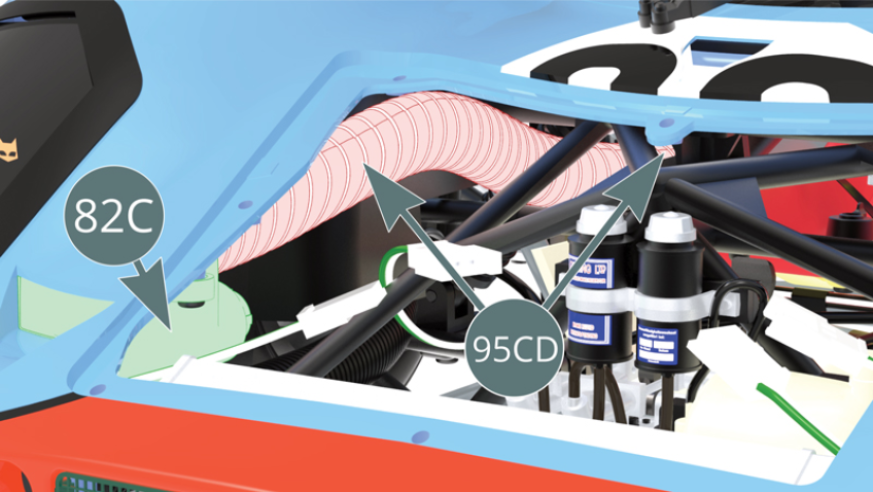
Fit the screw threaded end of the right duct (95CD) to the nozzle of the right air intake (82C) - closest to the bodywork. Place the connectors for the headlight LED cables (35F) into the position indicated opposite.
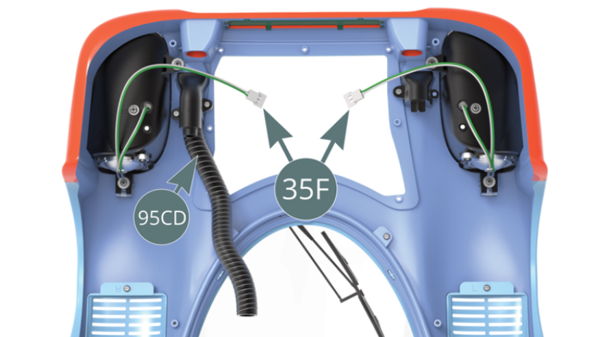
Step 3
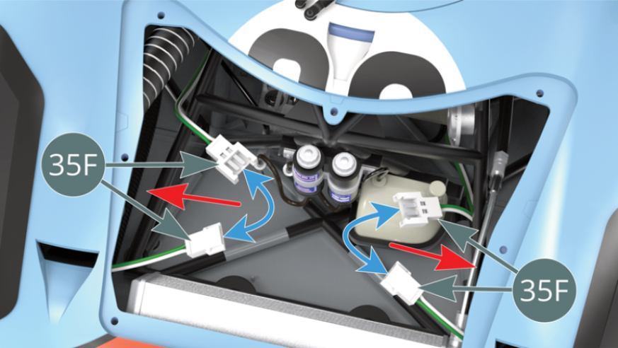
At the front end of the chassis, place the connectors for the headlight LED cables (35F) into the position indicated opposite.
Step 4
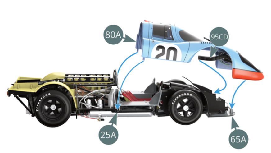
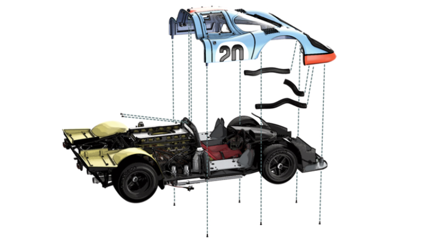
Position the body (80A) on the lower frame (25A) and on the flat front floor (65A).
At the same time, guide the right duct (95CD) through the tubular trellis as illustrated in the next step.
Step 5
Pass the right duct (95CD) through the tubular trellis below the dashboard.
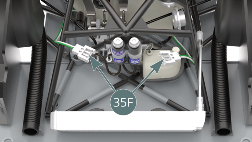
Step 6
Join the connectors for the headlight LED cables (35F), then move them sideways to conceal them (red arrows).
Step 7
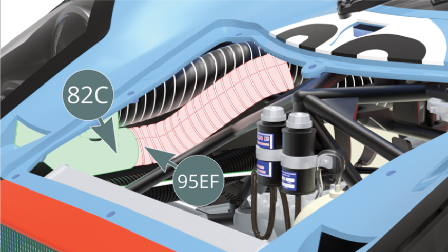
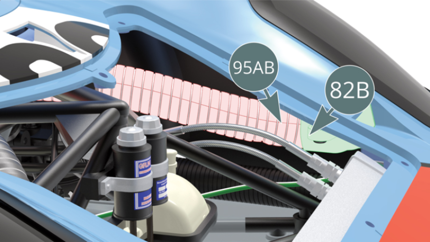
Attach the screw threaded end of the right duct (95EF) to the nozzle of the right air intake (82C). Pass the left duct (95AB) through the tubular trellis, which can be made easier by gently pulling it from the left open door.

Step 8
Attach the screw-threaded end of the left duct (95AB) to the nozzle of the left air intake (82B) with the help of a tweezer.
Secure the body from below, to the front flat floor (65A), the lower frame (25A) and the left (35A) and right (35B) mudguards, using six JM screws.

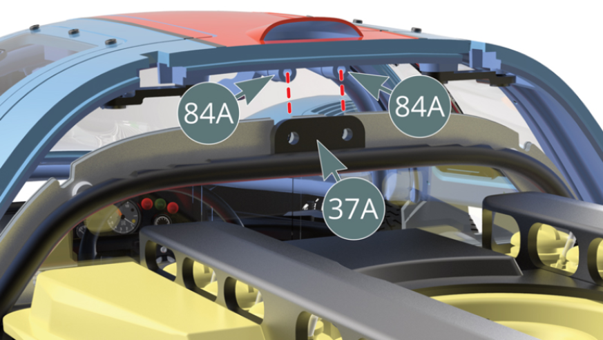
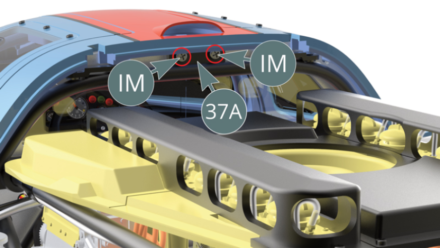
Step 9
Attach the tab of the cockpit bulkhead (37A) and the two ends of the upper roll bar (84A) together using two IM screws - illustrations above.
ASSEMBLY DIAGRAM

GENERAL VIEW
Kit 96
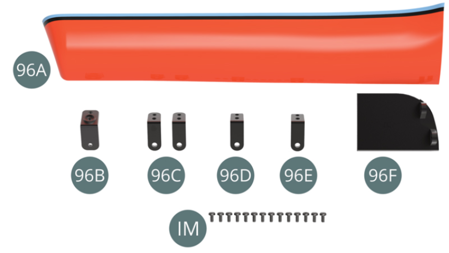
Parts of kit
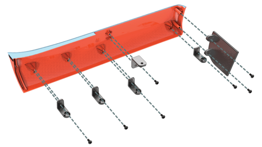
- 96A Left rocker panel
- 96B Upper bracket
- 96C Bracket #1 (x 2)
- 96D Bracket #2
- 96E Bracket #3
- 96F Front panel
- Screw IM M 1.7 x 3.5 mm (x 14)
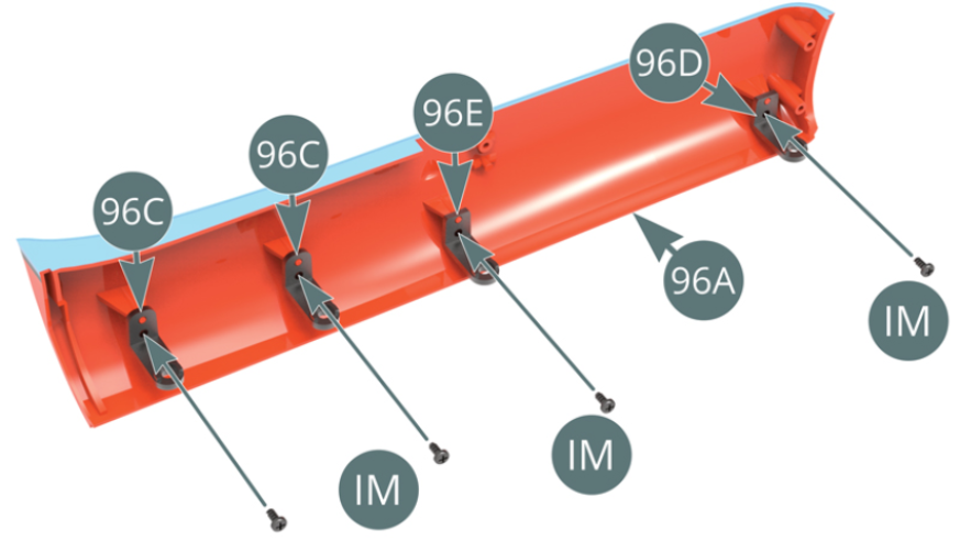
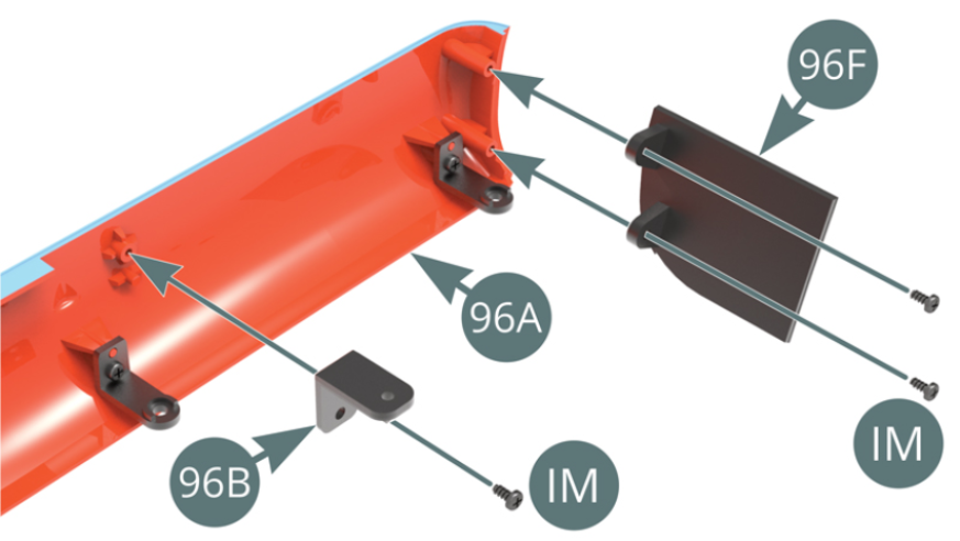
Step 1
Position the brackets (96D #2, 96E #3) and the two brackets (96C #1) on the left rocker panel (96A), then secure them with four IM screws. Position the upper bracket (96B) and the front panel (96F) on the left rocker panel (96A), then secure them with three IM screws.
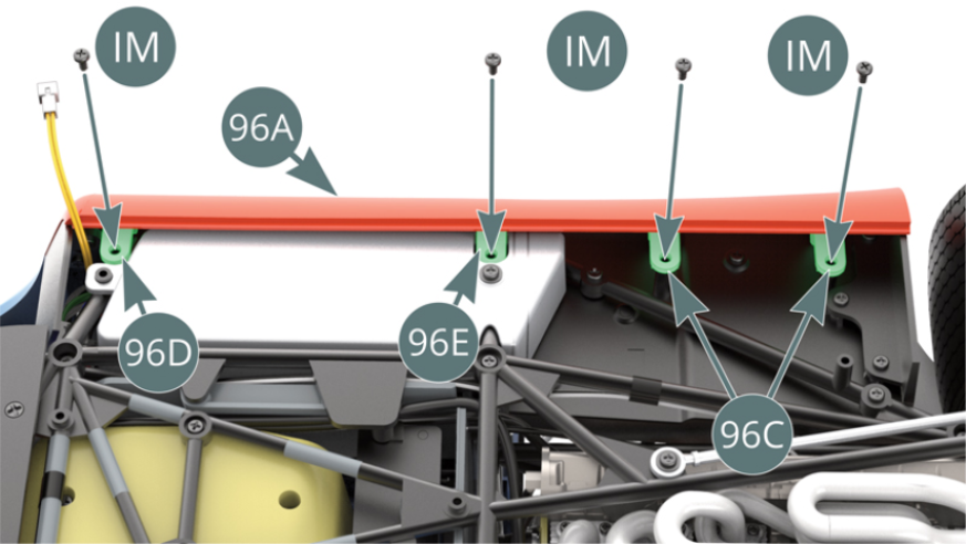
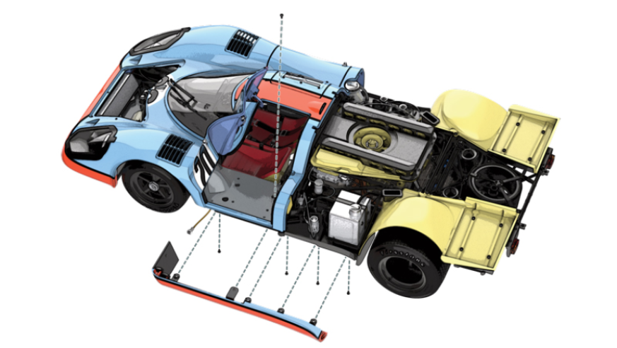
Step 2
Position the left rocker panel (96A) on the mounting points of the lower frame (25A) and of the left side platform (69A), then secure with four IM screws - illustrations opposite and below. Be sure to conceal the connection cables behind the front panel (96F) - red arrow - and the yellow cable should remain extended.

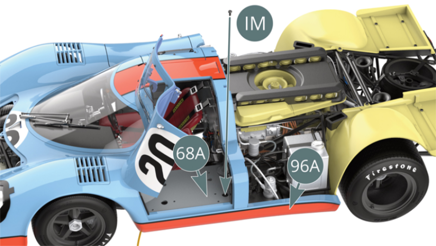
Step 3
Open the left door and secure the left rocker panel (96A) - via the upper bracket 96B - to the chassis (31B) using an IM screw, through an opening in the rear of the left cockpit housing (68A).
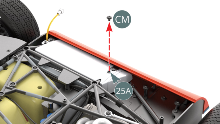
Step 4
Remove the CM screw from under the lower frame (25A), as it is no longer required.
ASSEMBLY DIAGRAM
GENERAL VIEW