English
 français
 Deutsch
 español
 italiano
 português


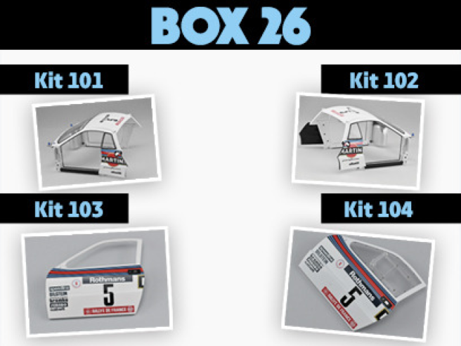
Box 26
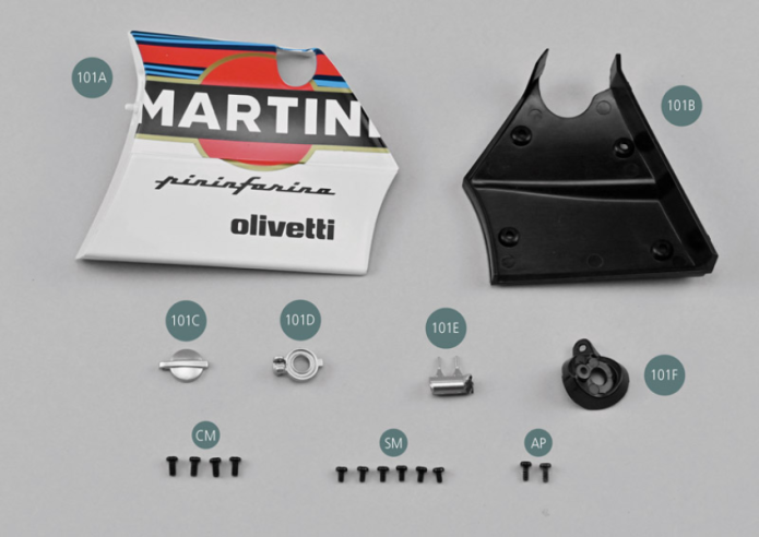
Parts of kit
- 101A Left rear side panel
- 101B Inner panel lining
- 101C Fuel cap
- 101D Fuel cap support
- 101E Plug shaft

Etape 1
- 101F Fuel cap housing
- Screw CM M 2.0 x 4 mm (x 4)
- Screw SM M 1.7 x 3 mm (x 6)
- Screw AP M 1.7 x 4 mm (x 2)
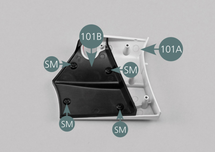
Placer le panneau arrière gauche 101A face intérieure tournée vers le haut. Positionner le doublage intérieur du panneau 101B comme indiqué sur la photo et le fixer avec quatre vis SM.
Etape 2
Place the left rear panel (101A) with the inside face facing up. Position the inner panel lining (101B) as shown in the photo and secure it with four SM screws.

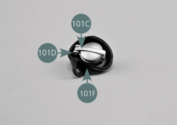
Positionner le bouchon de réservoir 101C sur le support de bouchon 101D et vérifier l’alignement des trous.
Détacher un axe de bouchon 101E de sa grappe de moulage avec un cutter. Insérer l’axe 101E à l’aide d’une brucelle dans le trou du bouchon 101C et du support 101D comme indiqué.
Vérifier que le bouchon s’ouvre correctement.
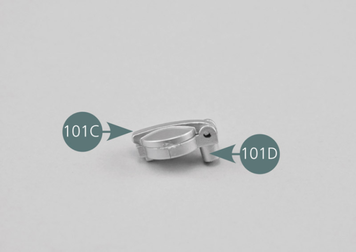
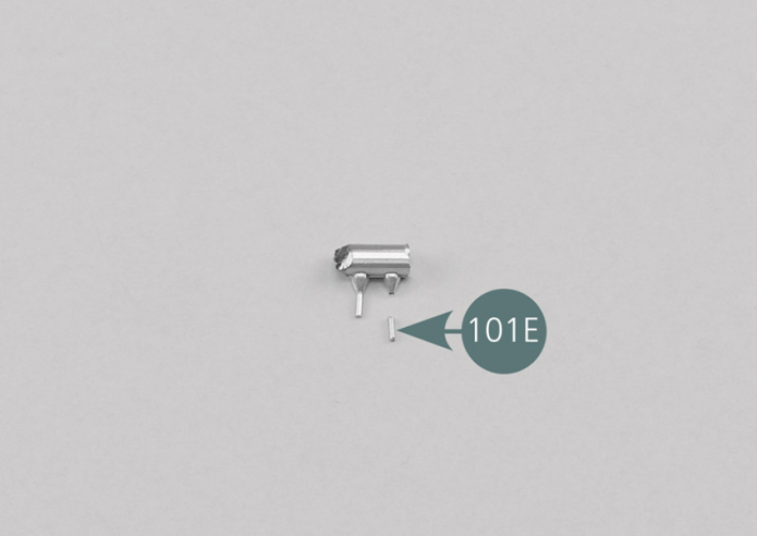
Position the fuel cap (101C) on the cap support (101D) and check the alignment of the openings. Detach a plug (101E) from its sprue with a tweezer. Insert the plug (101E) - using tweezers - into the opening in the cap (101C) and the support (101D) as shown. Check that the cap opens correctly.

Etape 3


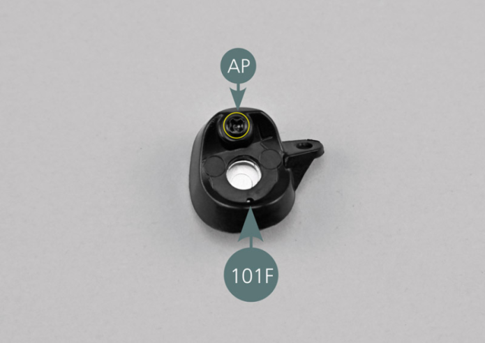
Positionner le bouchon de réservoir et son support dans le boîtier de bouchon 101F et le fixer par l’arrière avec une vis AP comme indiqué sur la photo.
Etape 4
Place the fuel cap and its support in the cap housing (101F) and secure it from the rear with an AP screw as shown in the photo.


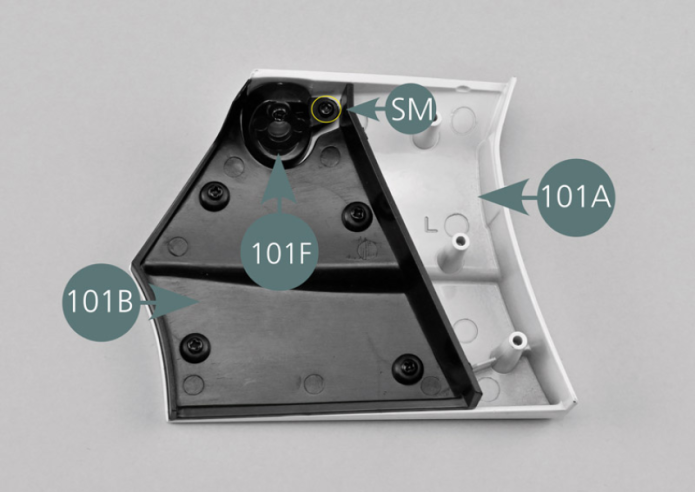
Positionner l’assemblage du bouchon de réservoir et du boîtier sur la face intérieure du panneau latéral arrière gauche 101A comme indiqué, puis le fixer avec une vis SM.
Etape 5
Position the fuel cap and housing assembly on the inside of the left rear side panel (101A) as shown, then secure it with an SM screw.

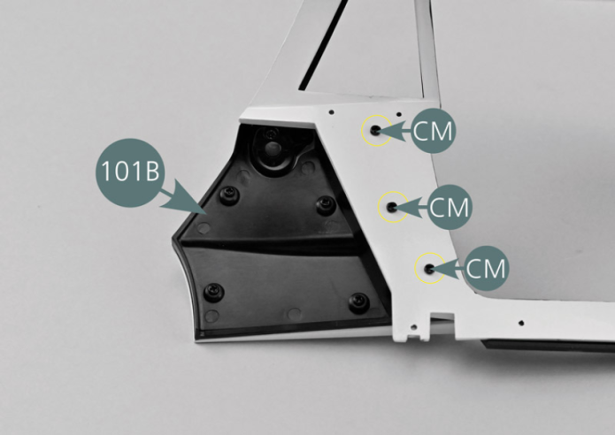
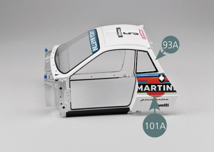
Positionner le panneau latéral arrière gauche 101A sous la glace de custode arrière gauche de la carrosserie centrale 93A, puis le fixer depuis l’intérieur avec trois vis CM.

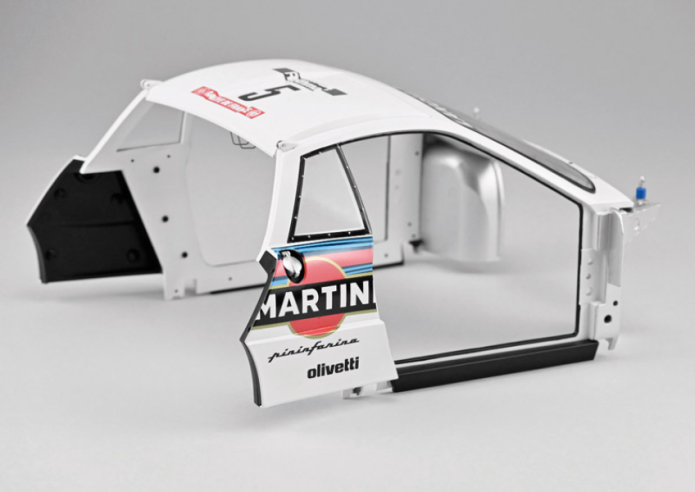
Vue générale
Place the left rear side panel (101A) under the left rear quarter window of the central part of the bodywork (93A), then secure it from the inside with three CM screws.
GENERAL VIEW
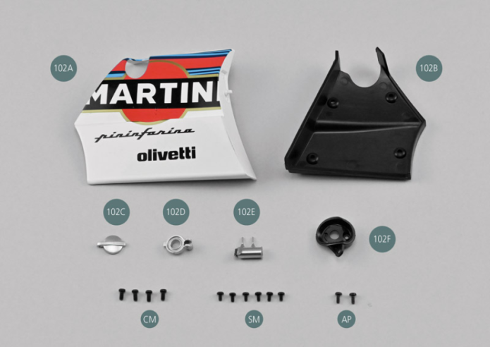
Parts of kit

Etape 1
- 102F Fuel cap housing
- Screw CM M 2.0 x 4 mm (x 4)
- Screw SM M 1.7 x 3 mm (x 6)
- Screw AP M 1.7 x 4 mm (x 2)
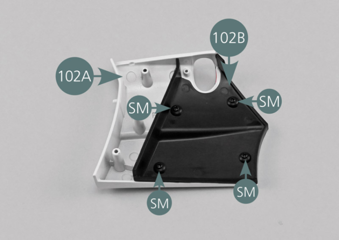
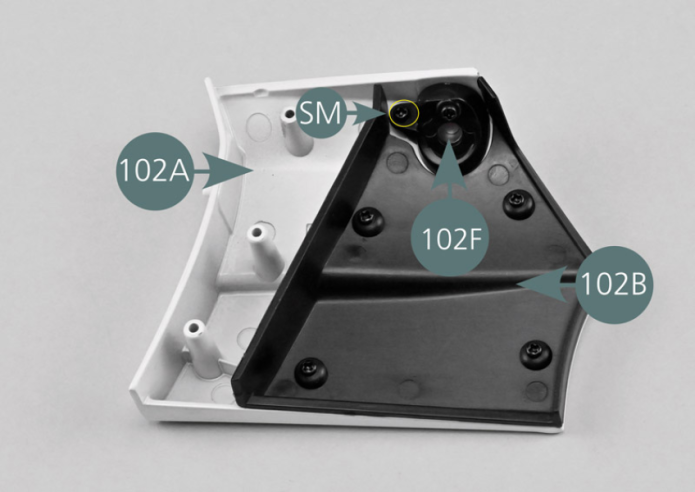
Placer le panneau arrière droit 102A face interne tournée vers le haut. Positionner le doublage intérieur du panneau 102B comme indiqué sur la photo et le fixer avec quatre vis SM.

Etape 2
Place the right rear panel (102A) with the inside face facing up. Position the inner panel lining (102B) as shown in the photo and secure it with four SM screws.
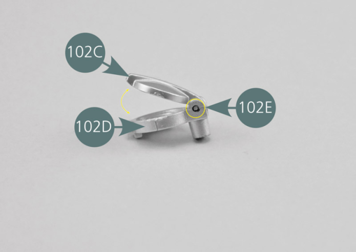
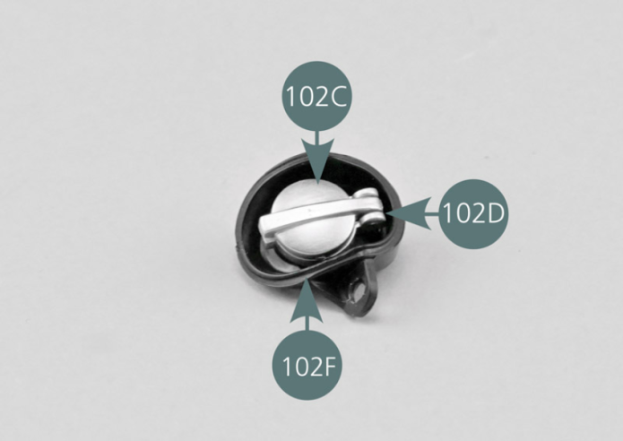
Positionner le bouchon de réservoir 102C sur le support de bouchon 102D et vérifier l’alignement des trous.
Détacher un axe de bouchon 102E de sa grappe de moulage avec un cutter.
Insérer l’axe 102E à l’aide d’une brucelle dans le trou du bouchon 102C et du support 102D comme indiqué.
Vérifier que le bouchon s’ouvre correctement.
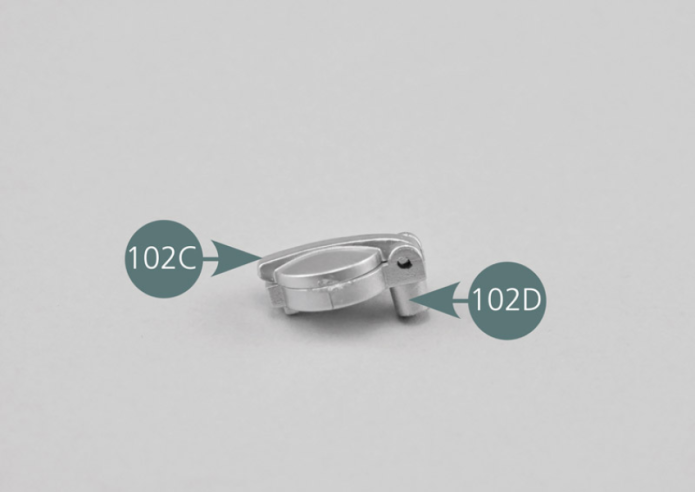
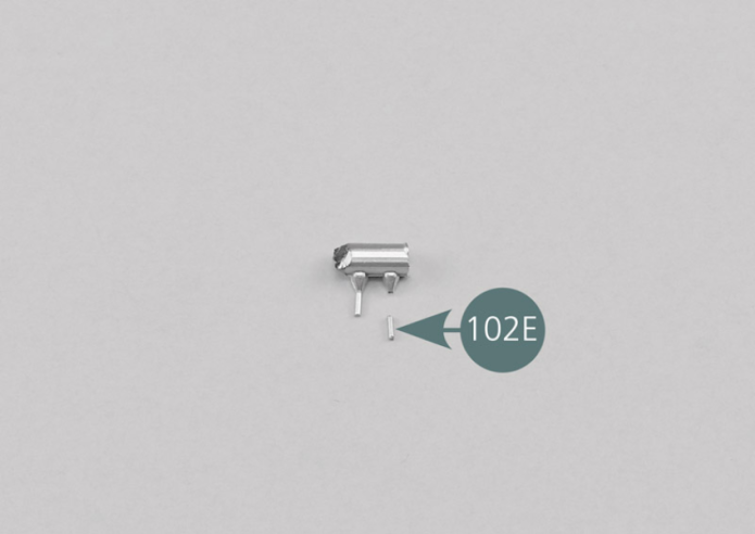
Position the fuel cap (102C) on the cap support (102D) and check the alignment of the openings. Detach a plug (102E) from its sprue with a cutter. Insert the plug (102E) by using tweezers into the opening in the cap (102C) and the support (102D) as shown. Check that the cap opens correctly.
Etape 3


Positionner le bouchon de réservoir et son support dans le boîtier de bouchon 102F et le fixer par l’arrière avec une vis AP comme indiqué sur la photo.

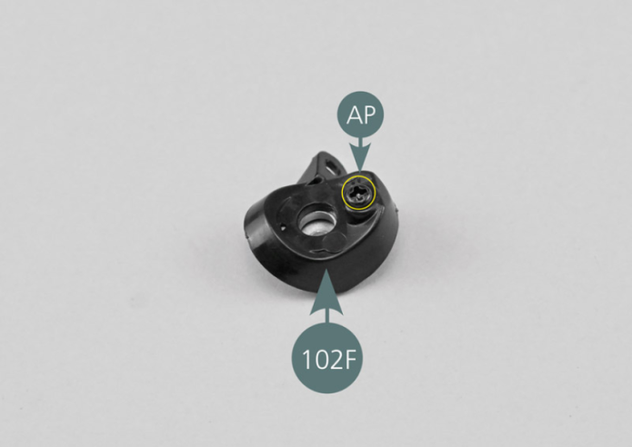
Etape 4
Place the fuel cap and its support in the cap housing (102F) and secure it from the rear with an AP screw as shown in the photo.

Positionner l’assemblage du bouchon de réservoir et du boîtier sur la face intérieure du panneau latéral arrière droit 102A comme indiqué, puis le fixer avec une vis SM.

Etape 5
Position the fuel cap and housing assembly on the inside of the right rear side panel (102A) as shown, then secure it with an SM screw.
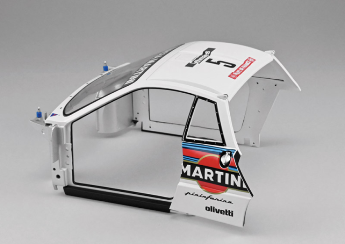
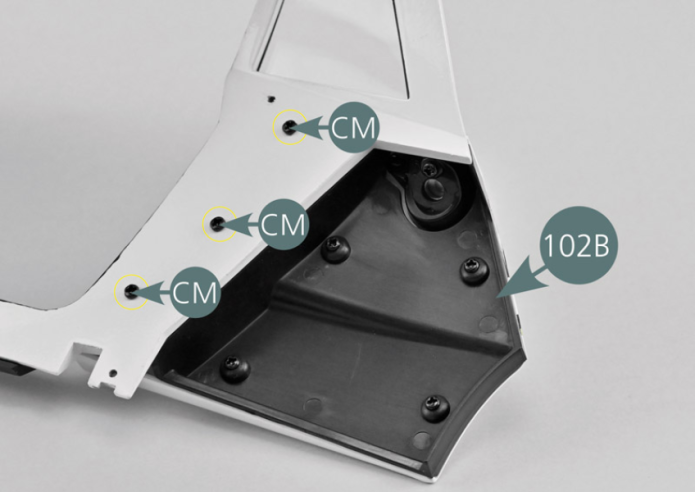
Positionner le panneau latéral arrière droit 102A sous la glace de custode arrière droite de la carrosserie centrale 93A, puis le fixer depuis l’intérieur avec trois vis CM.
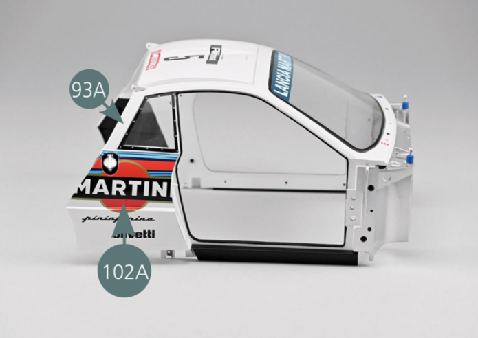
Vue générale
Place the right rear side panel (102A) under the right rear quarter window of the central part of the bodywork (93A), then secure it from the inside with three CM screws.

GENERAL VIEW
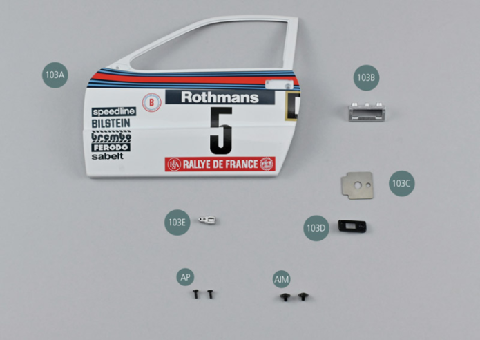
Parts of kit

Etape 1
- 103E Door handle
- Screw AP M 1.7 x 4 mm (x 2)
- Flat head screw AIM M 2 x 3 x 6 mm (x 2)
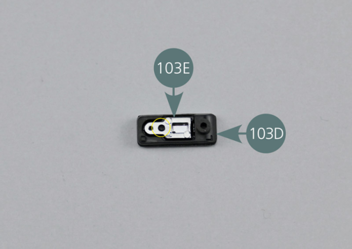
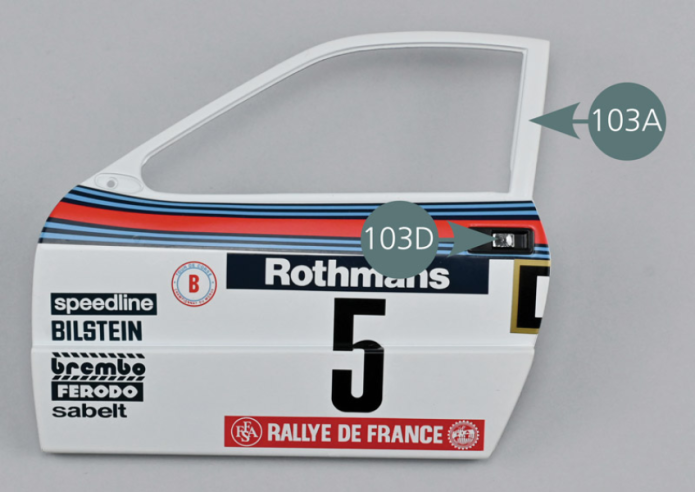
Placer le support de poignée de porte 103D face intérieure tournée vers le haut comme indiqué. Insérer la poignée de portière 103E dans le logement prévu en vérifiant que le téton est correctement aligné avec le trou (cercle jaune). La poignée de portière est assemblée à l’envers.
Etape 2
Place the door handle support (103D) with the inside facing up – see picture. Insert the door handle (103E) into the housing, ensuring that the pin is correctly aligned with the opening (yellow circle). The door handle is assembled upside down.


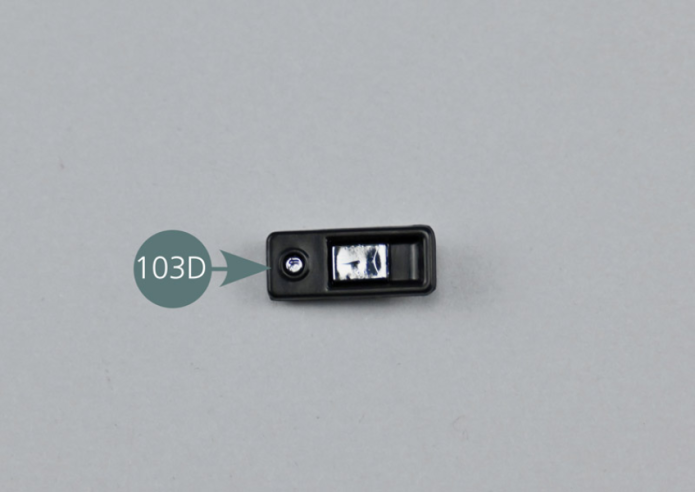
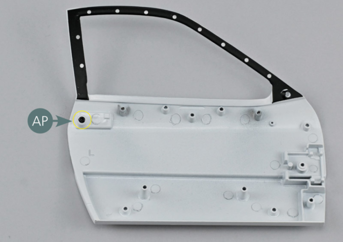
Positionner le support de poignée de porte 103D sur la portière gauche 103A, en faisant correspondre le trou de fixation comme indiqué.
Fixer le support de poignée de porte 103D depuis la face intérieure de la portière avec une vis AP.
Etape 3
Position the door handle support (103D) on the left door (103A), matching the mounting opening as per picture. Secure the door handle support (103D) from the inside of the door with one AP screw.


Positionner la charnière de portière 103B sur la face intérieure de la portière 103A. Vérifier la bonne orientation de la charnière 103B.
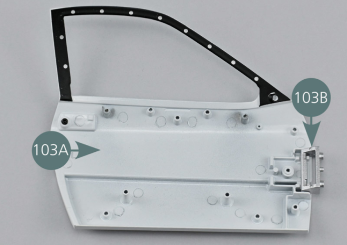
Position the door hinge (103B) on the inside of the door (103A). Check the correct orientation of the hinge (103B).
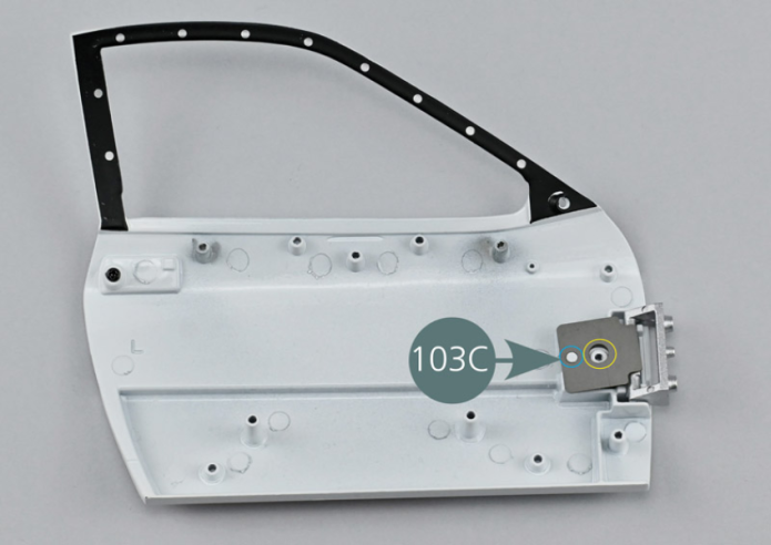
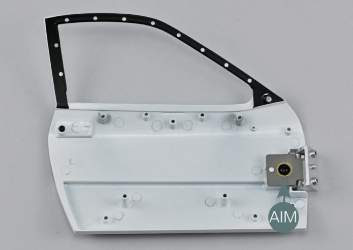
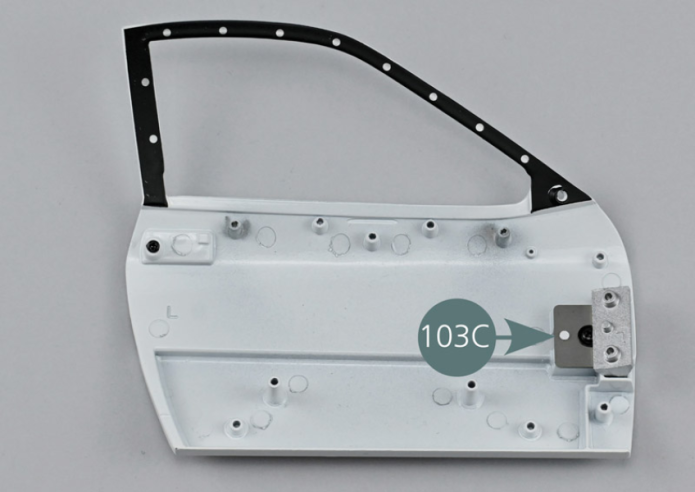
Position the hinge spring (103C) by centering the mounting opening with the seat of the screw (yellow circle) and aligning the rear pin with the rear opening of the spring (blue circle).
Secure the hinge spring (103C) with an AIM screw. Check that the hinge spring (103C) can move and has sufficient strength. If it is too loose, tighten the screw further.
Vue générale

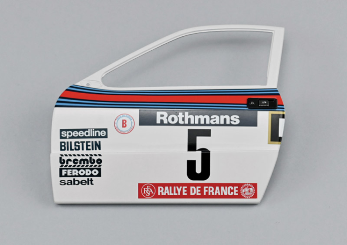
GENERAL VIEW
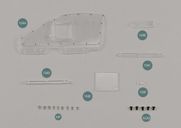
Parts of kit

Etape 1
- 104E Slidable ventilation window
- 104F Window Latch
- Screw MP M 1.2 x 3 mm (x 9)
- Screw AGM M 2.0 x 3 mm (x 5)
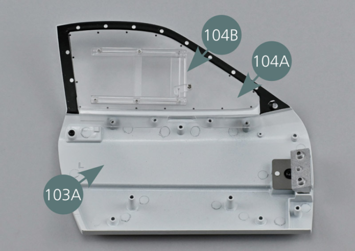
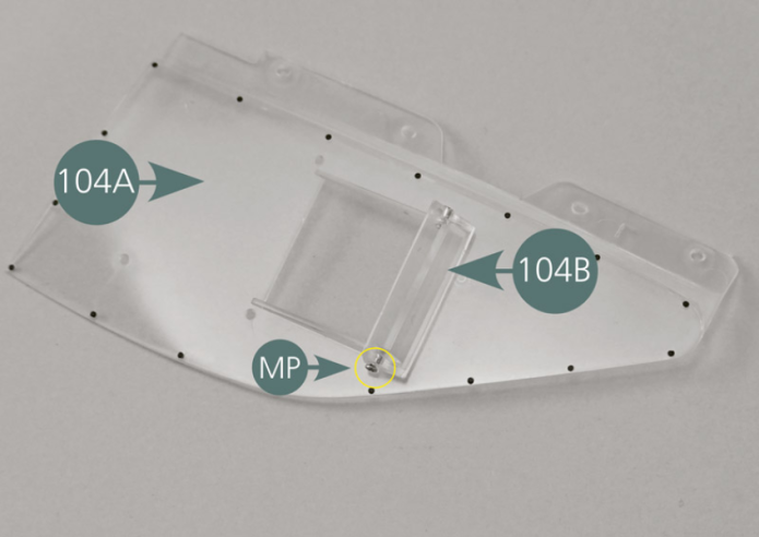
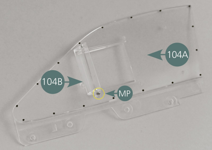
Positionner le déflecteur 104B sur l’extérieur de la vitre 104A et le fixer avec deux vis MP comme indiqué.
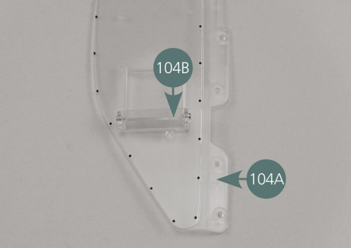

Position the deflector (104B) on the outside of the window (104A) and secure it with two MP screws as shown.
Etape 2

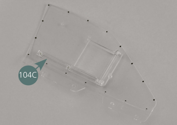
Positionner le guide inférieur 104C sur la face intérieure de la vitre 104A en veillant à ce que la rainure soit orientée vers le haut comme indiqué sur la photo.
Centrer la goupille située sur la droite de la fenêtre dans le trou du guide inférieur comme indiqué (cercle jaune).
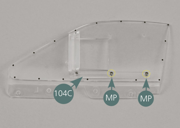
Tout en le maintenant en position, fixer le guide 104C depuis l’extérieur de la vitre 104A avec deux vis MP.
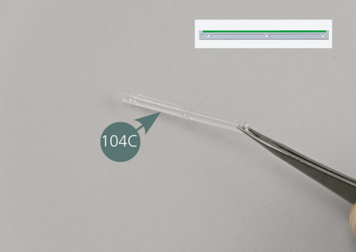
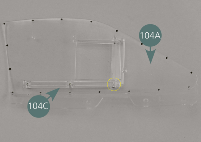
Place the lower window guide (104C) on the inside of the window (104A) ensuring that the groove is facing upwards as per picture. Center the pin located on the right of the window in the opening of the lower window guide as shown (yellow circle). While holding it in position, secure the guide (104C) from the outside of the window (104A) with two MP screws.


Etape 3
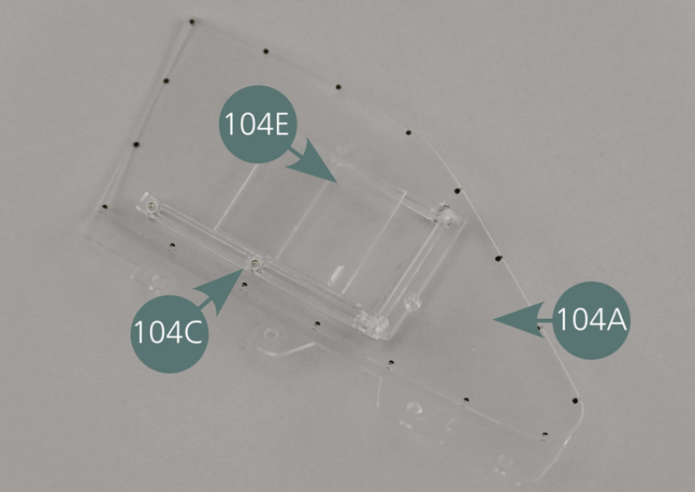
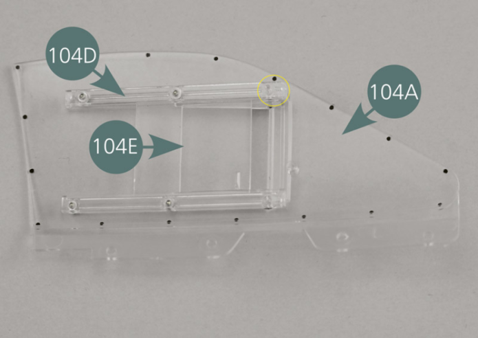
Positionner la fenêtre coulissante 104E dans la rainure du guide inférieur 104C à l’intérieur de la vitre 104A. Vérifier que la poignée est bien orientée vers l’avant de la fenêtre.
Etape 4
Position the sliding window (104E) in the groove of the lower window guide (104C) inside the window (104A). Check that the handle is oriented towards the front of the window.

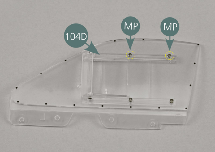
Positionner le guide supérieur 104D sur la face intérieure de la vitre 104A en veillant à ce que la rainure soit orientée vers le bas comme indiqué sur la photo.
Centrer la goupille située sur la droite de la fenêtre dans le trou du guide supérieur comme indiqué (cercle jaune).
Tout en maintenant le guide et la fenêtre en position, fixer le guide 104D depuis l’extérieur de la vitre 104A avec deux vis MP.
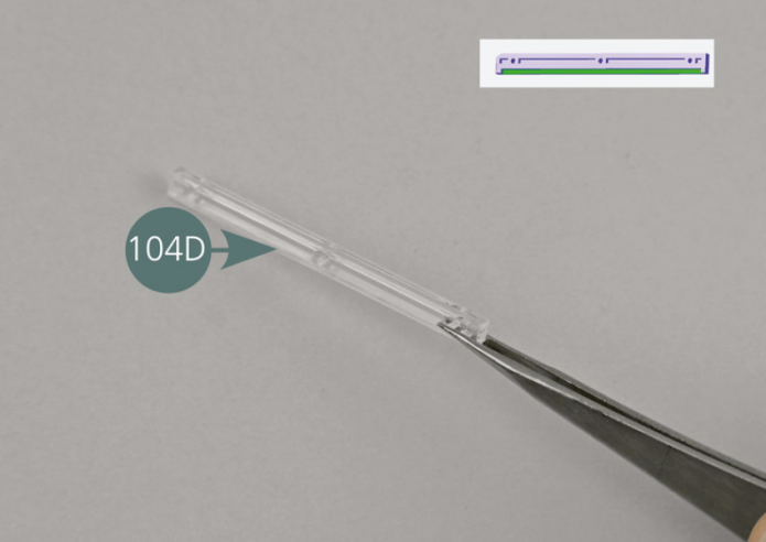

Position the upper window guide (104D) on the inside of the window (104A) ensuring that the groove is facing downwards as per picture. Center the pin located on the right of the window into the opening of the upper window guide as shown (yellow circle). While holding the guide and the window in position, secure the guide (104D) from the outside of the window (104A) with two MP screws.
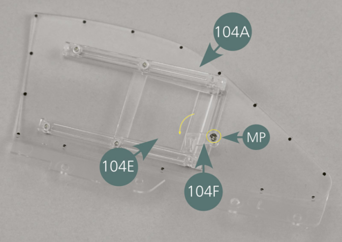
Etape 5

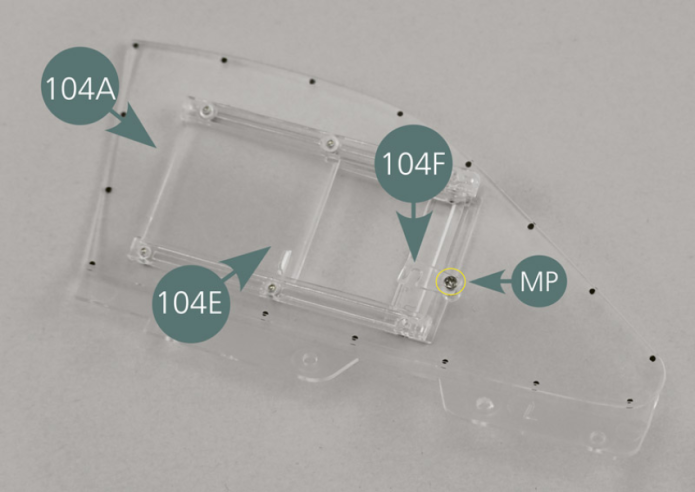
Positionner le loquet 104F dans l’ouverture de la poignée de la fenêtre coulissante 104E et le fixer avec une vis MP. Vérifier que le loquet 104F tourne aisément et qu’il bloque correctement la fenêtre coulissante 104E. Si besoin, serrer ou desserrer la vis pour un bon ajustement.

Etape 6
Position the latch (104F) into the opening of the handle of the sliding window (104E) and secure with an MP screw. Check that the latch (104F) turns easily and that it locks the sliding window (104E) correctly. If necessary, tighten or loosen the screw for a proper fit.

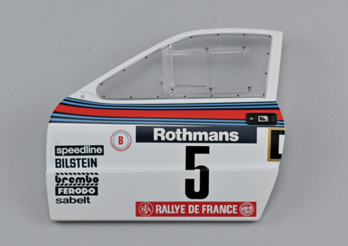
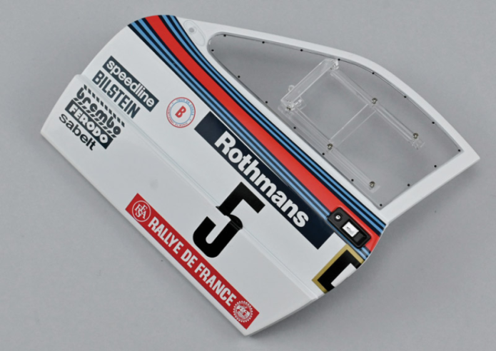
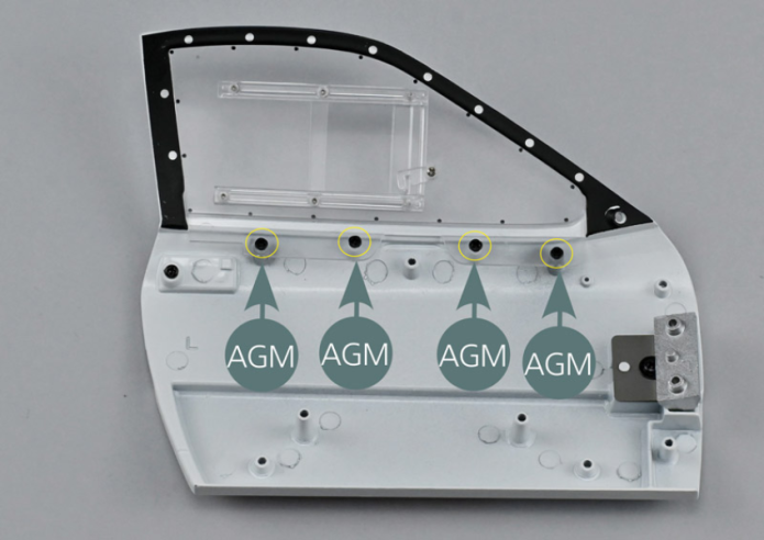
Positionner la vitre gauche 104A sur la face intérieure de la portière gauche 103A, avec le déflecteur orienté vers l’extérieur. Fixer la vitre 104A sur la portière avec quatre vis AGM.

Vue générale
Place the left window (104A) on the inside of the left door (103A), with the deflector facing outwards. Secure the window (104A) to the left door with four AGM screws.