English
 français
 Deutsch
 español
 italiano
 português


Box 4
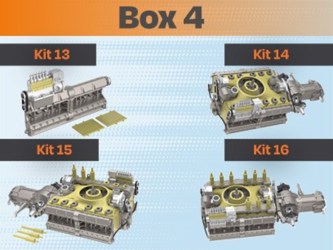
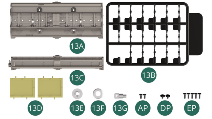
Kit 13
Parts of kit
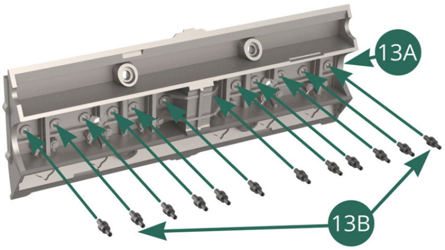
- 13A Left cylinder head
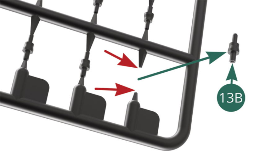
- 13B Spark plugs (x 12 + 6 additional)
- 13C Exhaust valve cover
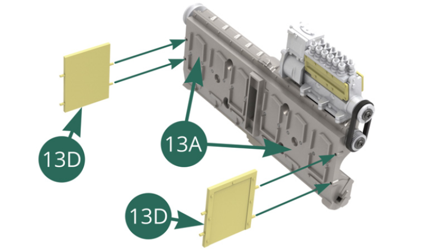
- 13D Partition (x 2)
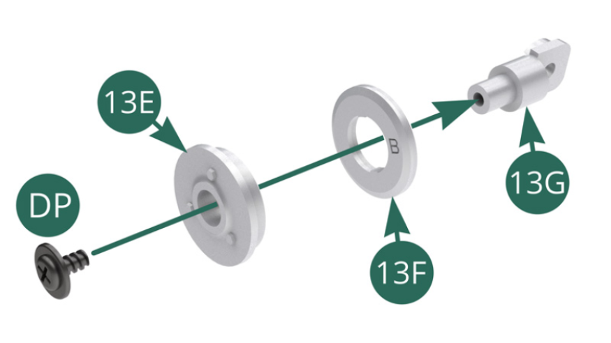
- 13E Outer pulley
- 13F Inner pulley
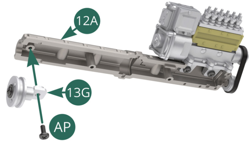
- 13G Pulley shaft
- AP Screw M 1.7 x 4 mm (x 2)
- DP Screw M 1.7 x 3 x 5 mm (x 2)
- EP Screw M 1.7 x 5 mm (x 5)
STEP 1
Position the inner 13F and outer 13E pulleys on axis 13G and secure them with a DP screw.
Position the pulley shaft 13G on the intake valve cover 12A and secure it with an AP screw.
STEP 2
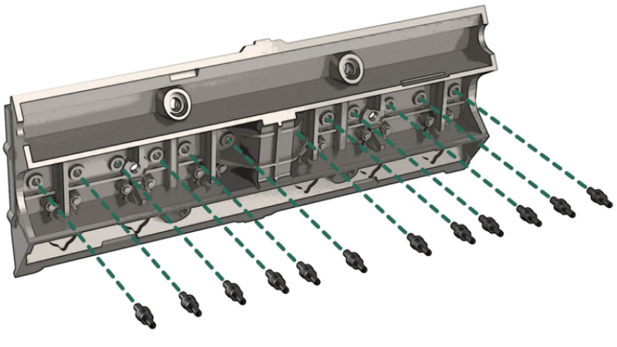
Detach twelve spark plugs 13B from the support using the pliers and tweezers, then position them on the left cylinder head 13A (illustrations opposite).
STEP 3
Position the exhaust valve cover 13C on the left cylinder head 13A and secure it with two EP screws.
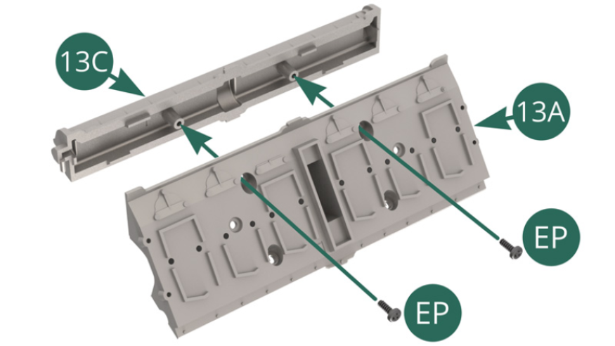
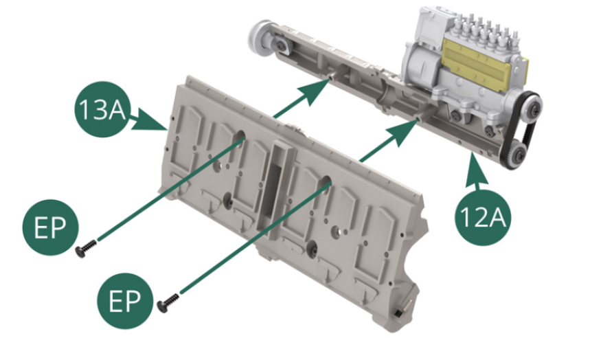
Position the intake valve cover 12A on the left cylinder head 13A and secure it with two EP screws.
STEP 4
Pre-assembly of the left cylinder head
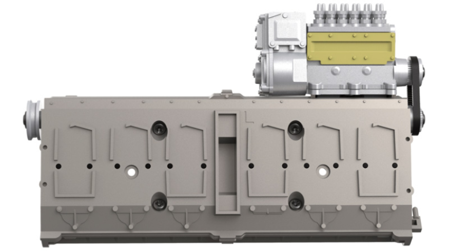
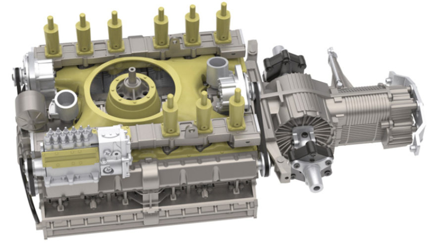
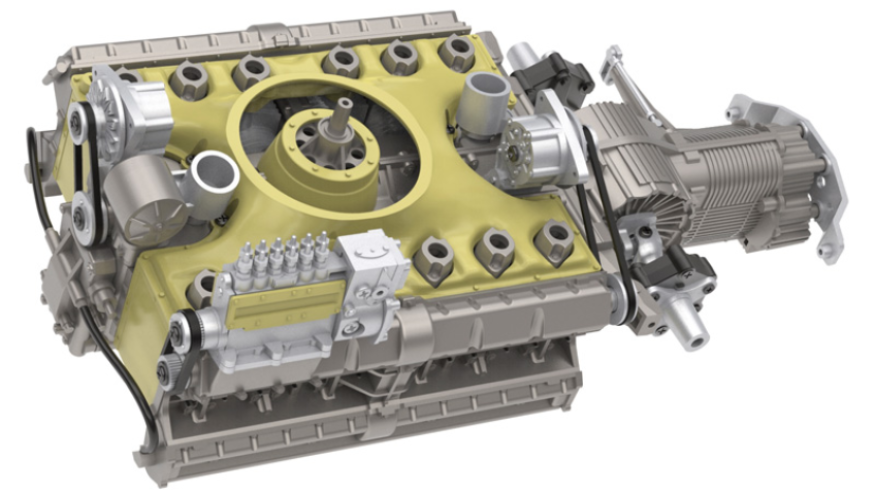
ASSEMBLY DIAGRAM
GENERAL VIEW
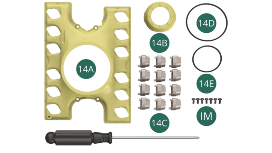
Kit 14
Parts of kit
- 14A Top of the air cooling chamber
- 14B Upper air flow guide
- 14C Air intake bracket (x 12)
- 14D Main generator belt
- 14E Secondary generator belt
- IM Screw M 1.7 x 3.5 mm (x 7)
STEP 1
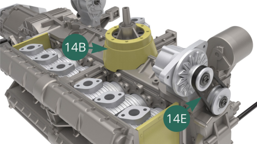
Position the upper air flow guide 14B on top of the Crankcase top 10A.
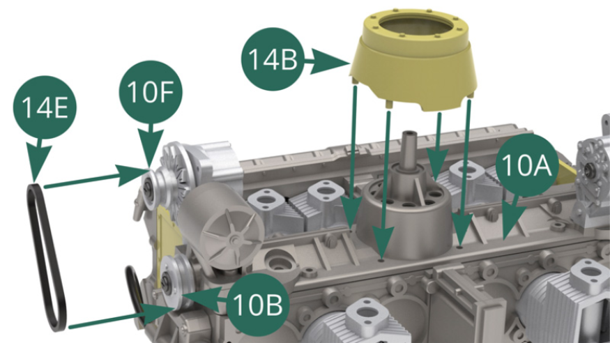
Position the secondary generator belt 14E on the pulleys 10F and 10B (illustrations above and opposite).
STEP 2
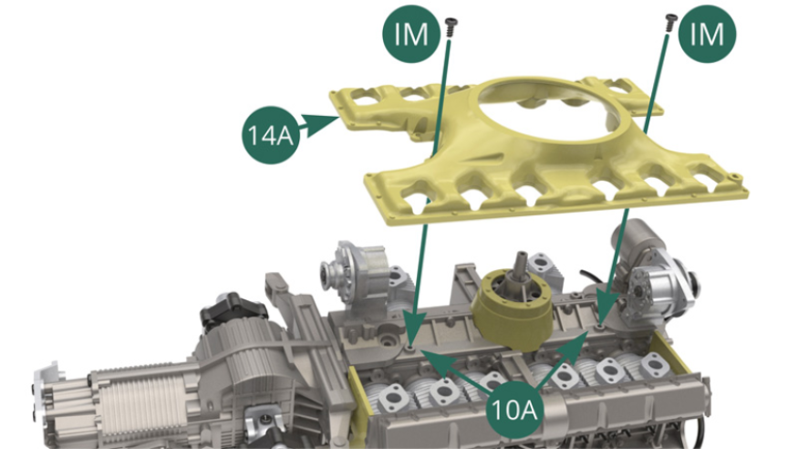
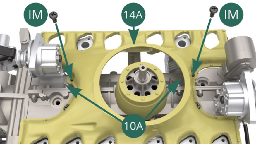
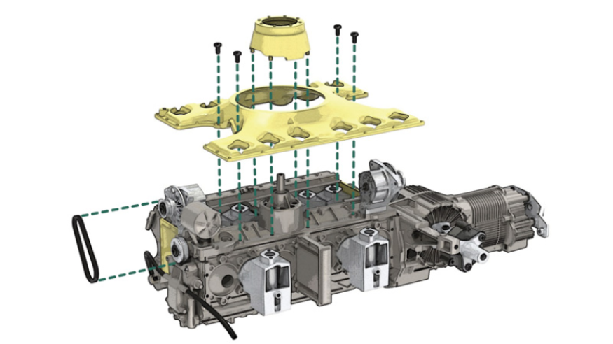
Position the top of the air cooling chamber 14A on the top of the Crankcase top 10A and secure it with four IM screws (illustrations opposite and below).
STEP 3
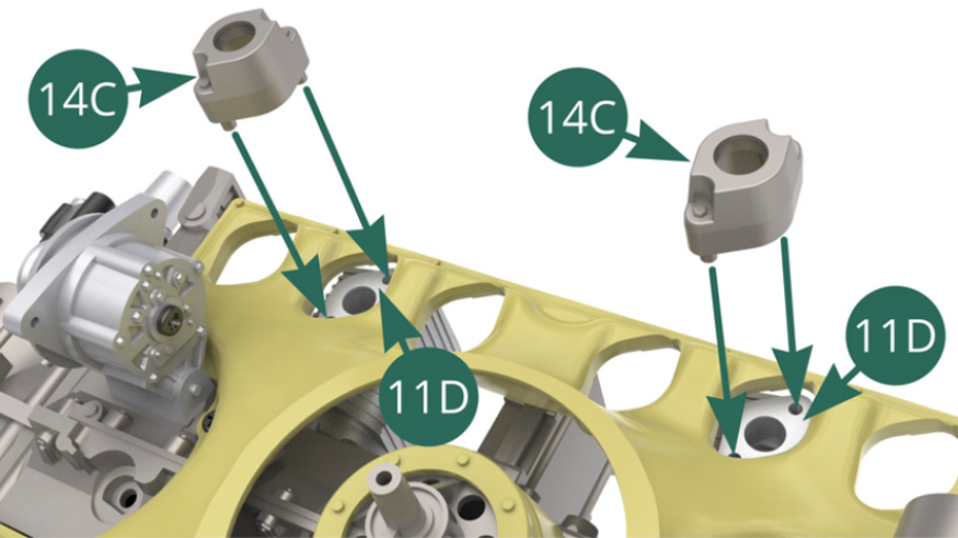
Position two 14C air intake brackets on the upper cylinder parts 11D on the left side of the engine.
Position a 10H distributor base on top of the 10A crankcase.
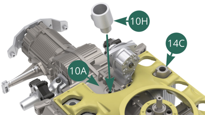
STEP 4
Position another 10H distributor base on top of the 10A crankcase.

Position six 14C air intake brackets on the upper cylinder parts 8F (x 4) and 7D (x 2) on the right side of the engine.
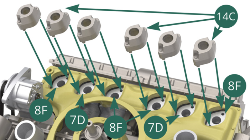
STEP 5
Six 14C air intake brackets installed on the right side of the engine.
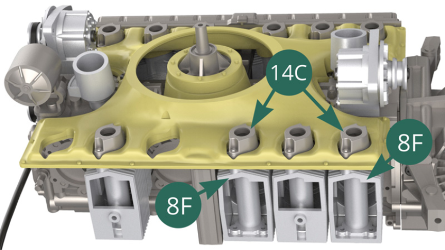
Position four 14C air intake brackets on four upper parts of 8F cylinder
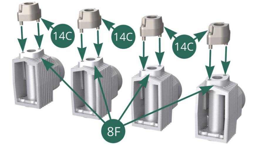
STEP 6
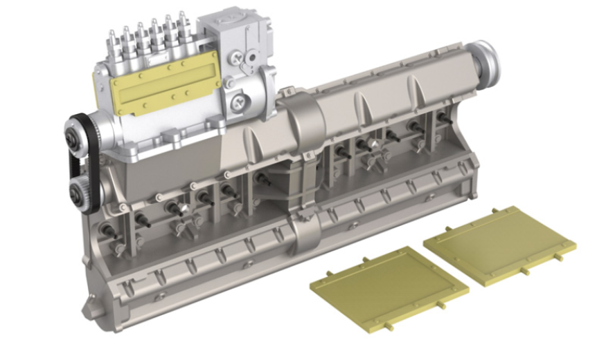
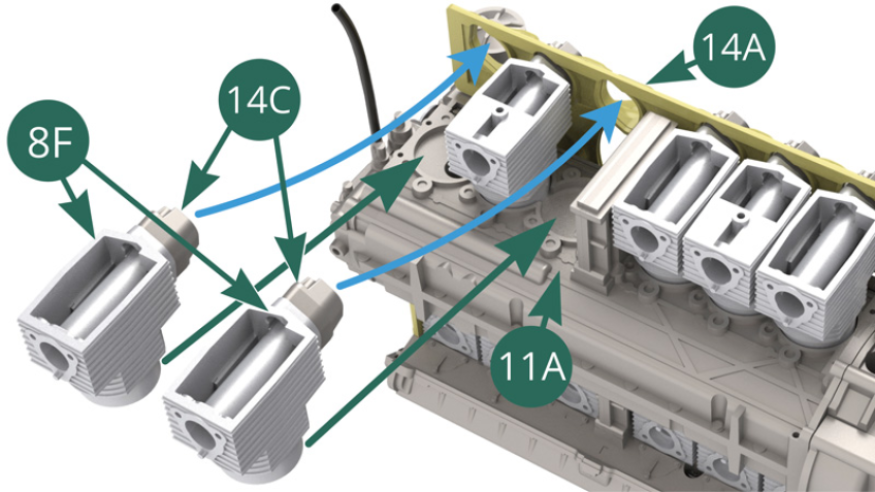
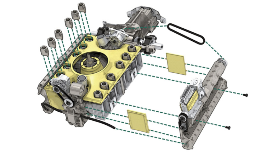
Position two upper cylinder parts 8F on the left engine block 11A by passing the two air intake supports 14C through the openings provided on the top of the air cooling chamber 14A, as indicated by the blue arrows. (illustrations above and opposite).
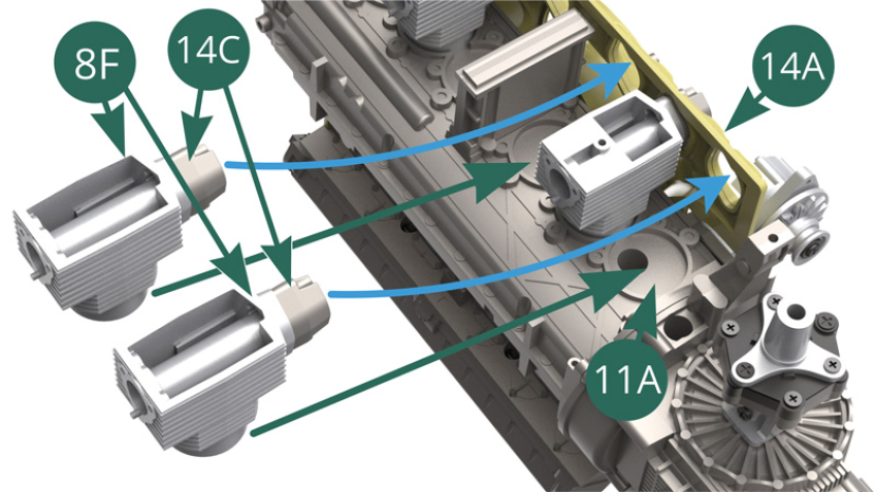
STEP 7
Position two other upper cylinder parts 8F on the left engine block 11A by passing the two air intake brackets 14C in the openings provided on the top of the air cooling chamber 14A as indicated by the blue arrows ( illustrations opposite).
STEP 8
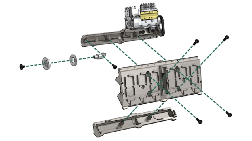
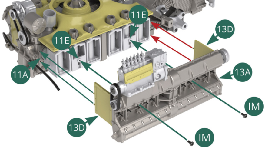
Position the two partitions 13D, riveted face outwards, at the ends of the cylinder head 13A.
STEP 9
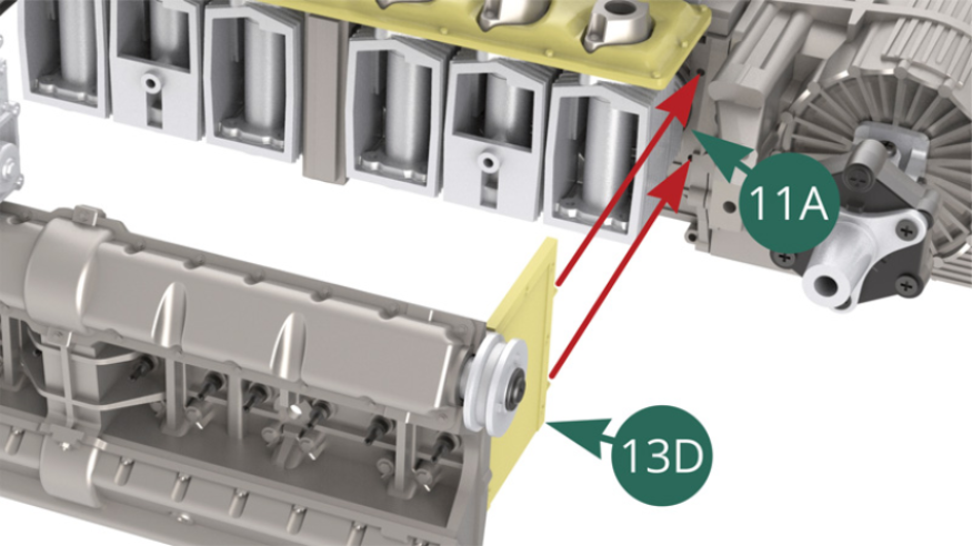
Position the left cylinder head 13A on the lower part of cylinder 11E making sure that the two partitions 13D are correctly positioned on the left engine block 11A, then fix the assembly with two IM screws (illustrations opposite and below) .
STEP 10
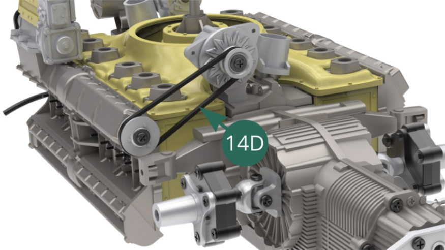
Position the generator main belt 14D on the pulleys 10F and 13E (illustrations opposite and below).
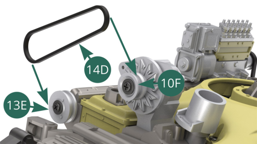
14D generator main belt installed.
STEP 11
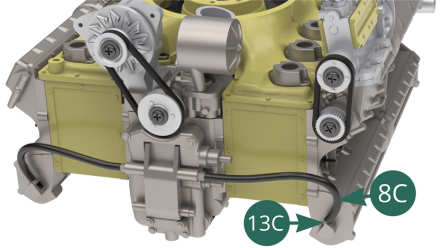
Connect the free end of the 8C oil hose to the nozzle located at the end of the 13C exhaust valve cover.
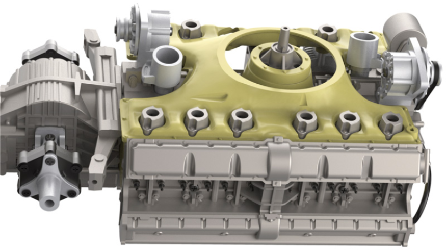
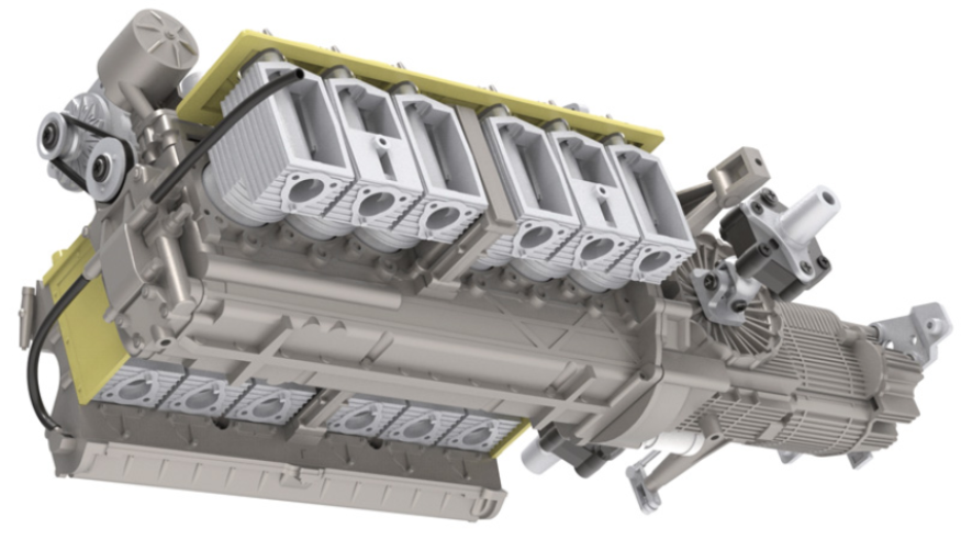
ASSEMBLY DIAGRAM

GENERAL VIEW
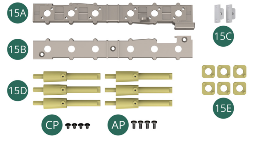
Kit 15
Parts of kit
- 15A Intake trumpet support top
- 15B Undercarriage for intake trumpets
- 15C End cover (x 2)
- 15D Admission Trumpet (x 6)
- 15E Inlet flange (x 6)
- CP Screw M 1.7 x 3 x 3 mm (x 4, flat head)
- AP Screw M 1.7 x 4 mm (x 4)
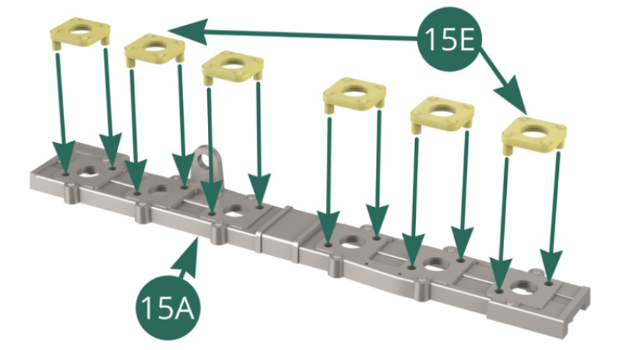
STEP 1
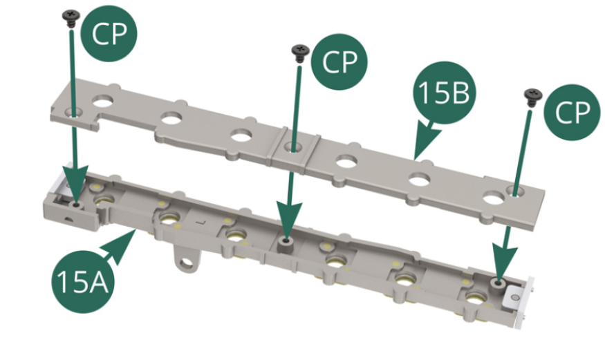
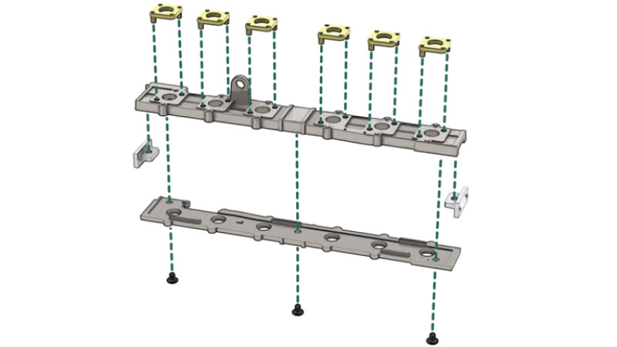
Position the six 15E inlet flanges on the top of the 15A intake trumpet support.
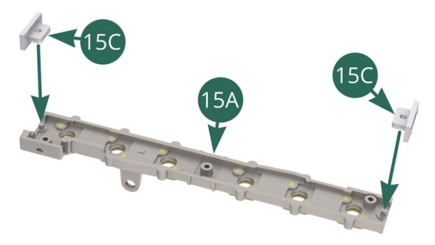
Position the two 15C covers at the ends of the 15A intake trumpet support top.
STEP 2
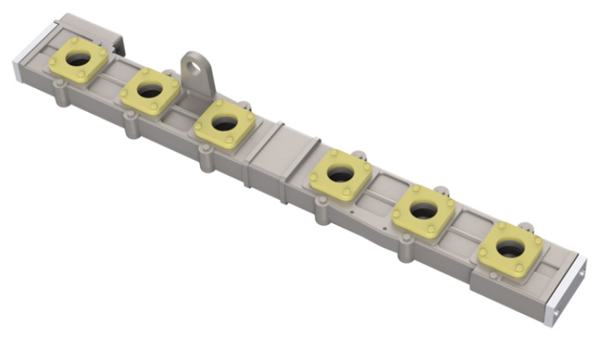
Position the inlet trumpet support underside 15B on the support top 15A and secure with three CP screws.
Pre-assembly of the intake trumpet holder
STEP 3
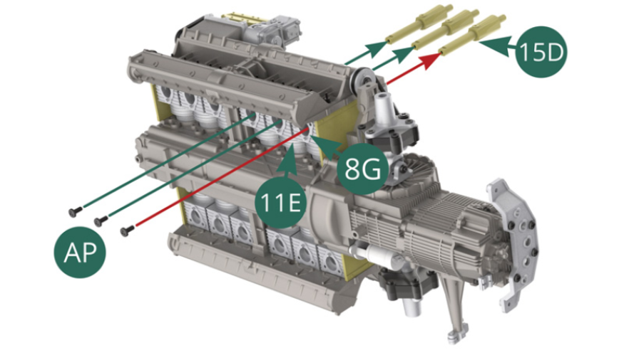
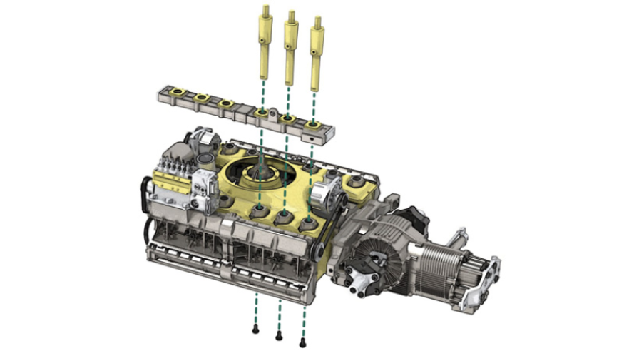
Position the 15B mission trumpet holder over the six 14C air intake brackets. Place three 15D inlet trumpets into the three corresponding 14C holders by passing them through their respective three 15E flanges.
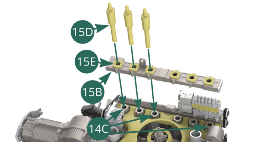
Check the correct orientation towards the outside of the holes on the 15D trumpets (red arrows in the illustrations opposite).
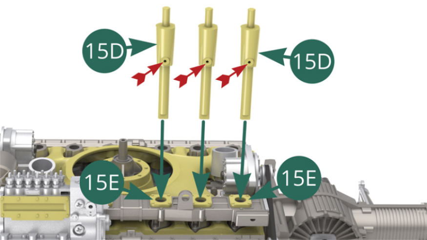
STEP 4
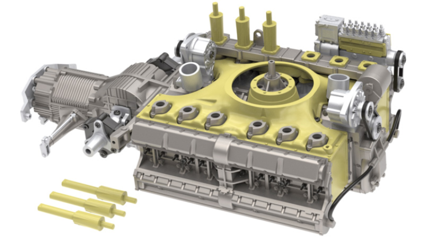
Attach three 15D intake trumpets to the 11E (x 1) and 8G (x 2) cylinder lower parts with three AP screws. Start with the 8G indicated by the red arrow (illustrations opposite and below).

ASSEMBLY DIAGRAM
GENERAL VIEW
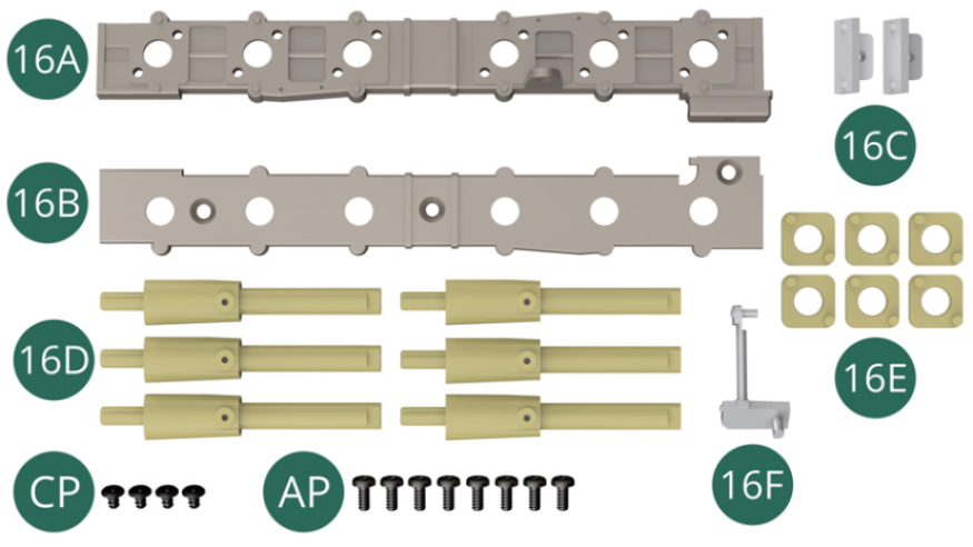
Kit 16
Parts of kit
- 16A Intake trumpet support top
- 16B Admission trumpet support underside
- 16C End cover (x 2)
- 16D Admission Trumpet (x 6)
- 16E Inlet flange (x 6)
- 16F Generator support arm
- CP Screw M 1.7 x 3 x 3 mm (x 4, flat head)
- AP Screw M 1.7 x 4 mm (x 8)
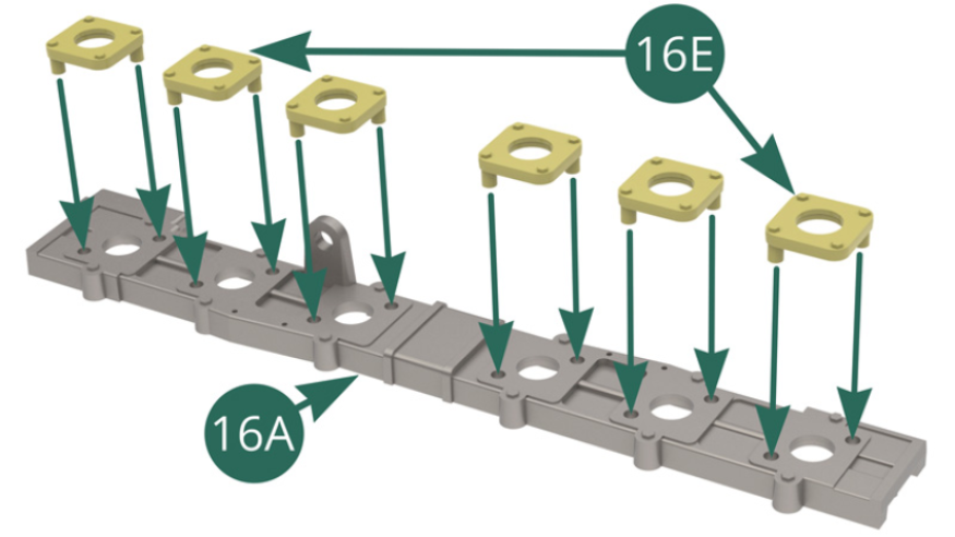
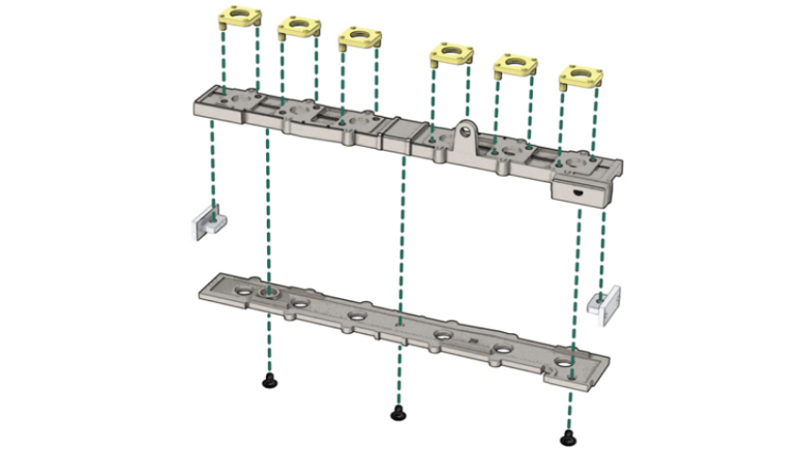
STEP 1
Position the six 16E intake flanges on the top of the 16A intake trumpet support. Position the two 16C covers at the ends of the 16A inlet trumpet support top.

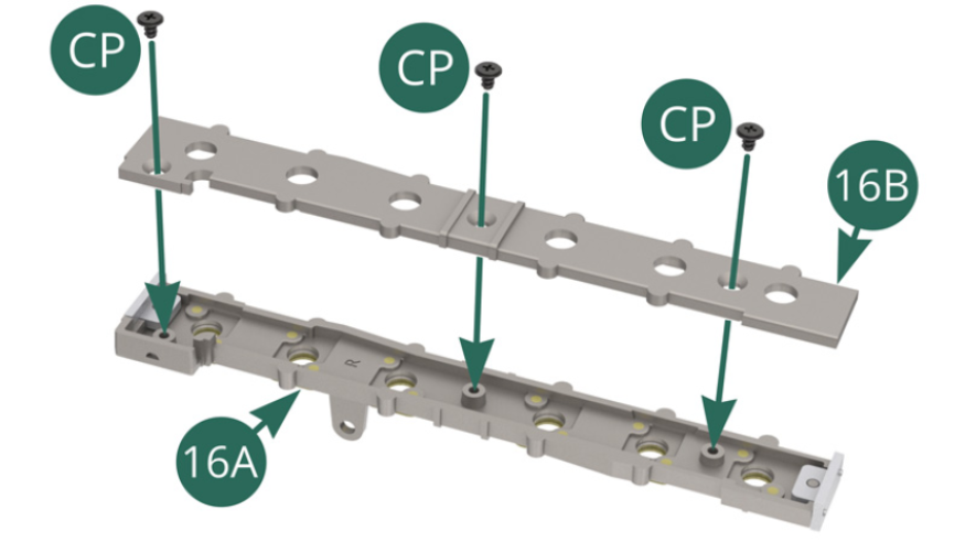
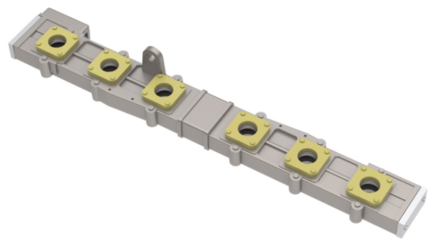
STEP 2
Position the inlet trumpet support underside 16B on the support top 16A and secure with three CP screws.
Pre-assembly of the intake trumpet holder
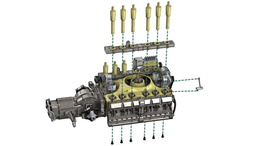
STEP 3
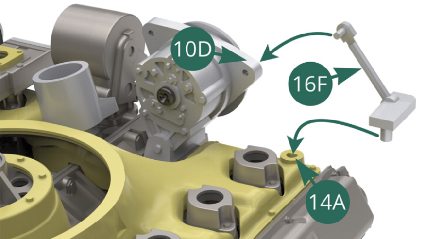
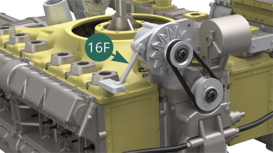
Position the support arm 16F on the bracket of the generator 10D and at the corner of the top of the air cooling chamber 14A (illustrations opposite and below).
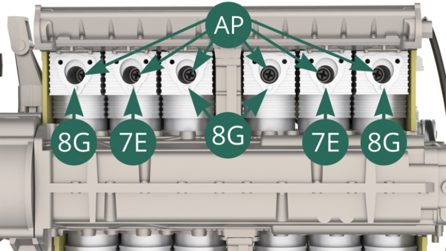
STEP 4
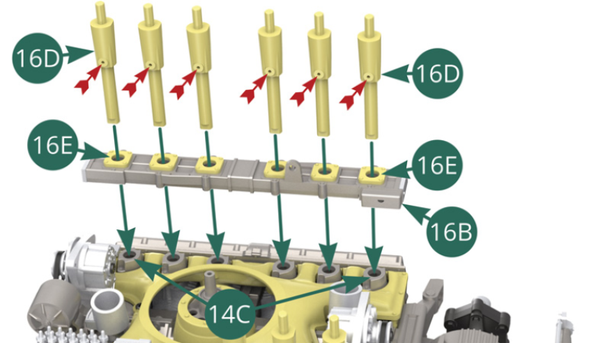
Position the 16B intake trumpet bracket over the six 14C air intake brackets. Place six 16D intake trumpets into the corresponding six 14C holders by passing them through their respective six 16E flanges. Check the correct orientation towards the inside of the holes on the 16D trumpets (red arrows)
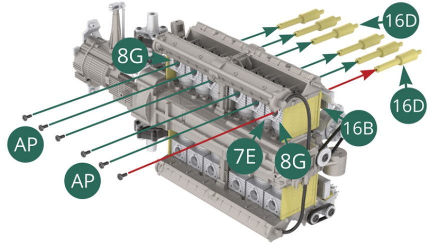
Secure the 16D intake trumpets to the 8G (x 4) and 7E (x 2) cylinder lower parts with six AP screws. Start with the 8G indicated by the red arrow (illustrations opposite and below).
ASSEMBLY DIAGRAM
GENERAL VIEW