English
 français
 Deutsch
 español
 italiano
 português


Box 6
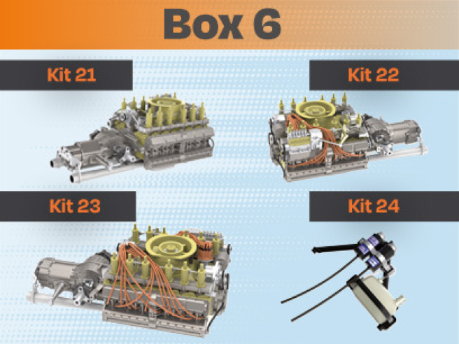
Kit 21
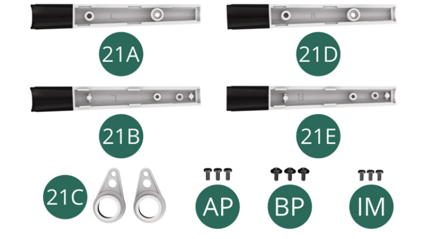
Parts of kit
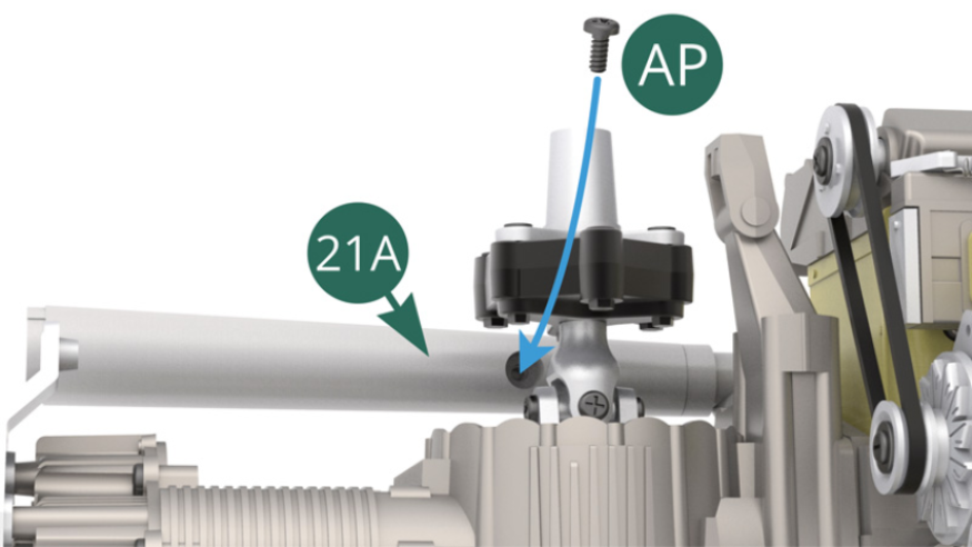
- 21A Upper left exhaust outlet
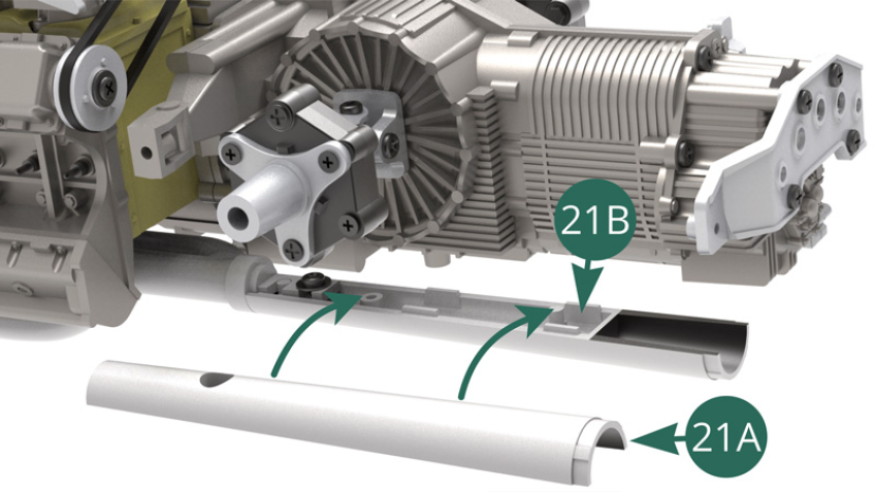
- 21B Lower left exhaust outlet
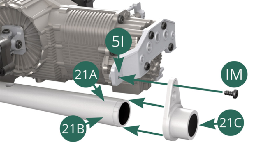
- 21C Exhaust outlet bracket (x 2)
- 21D Upper right exhaust outlet
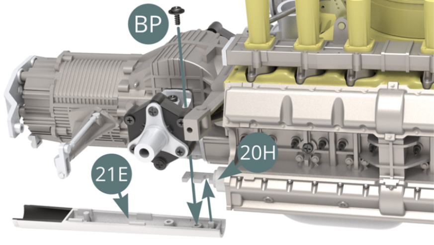
- 21E Lower right exhaust outlet
- AP screw M 1.7 x 4 mm (x 3)
- BP screw M 1.7 x 4 x 5 mm (x 3)
- IM screw M 1.7 x 3.5 mm (x 3)
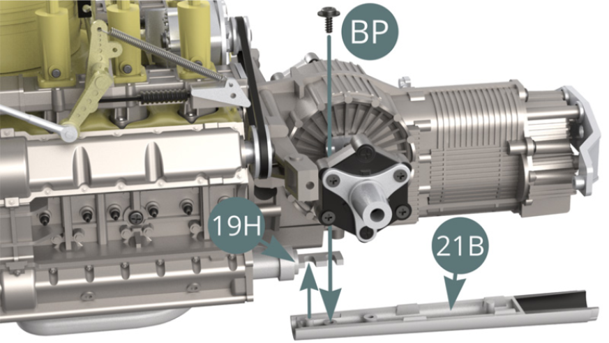
STEP 1
Position Lower left exhaust outlet (21B) on Exhaust manifold (19H) and secure it with a BP screw.
STEP 2
Position Upper left exhaust outlet (21A) on Lower left exhaust outlet (21B) and secure it with an AP screw (illustrations below).
STEP 3
Position Exhaust outlet bracket (21C) on the Upper and lower left exhaust outlet (21A/21B) as well as on the Exhaust pipe support (5I), then secure it on the latter using an IM screw.
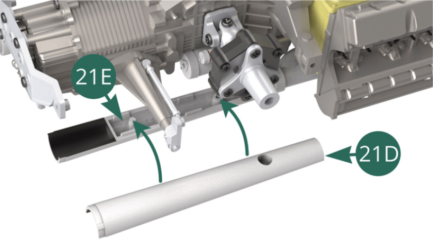
Position the Lower right exhaust outlet (21E) on the Exhaust manifold (20H)) and fix with a BP screw.
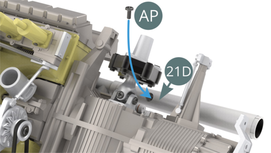
STEP 4
Position the Upper right exhaust outlet (21D) on the Lower left exhaust outlet (21E)) and secure with an AP screw (illustrations below).
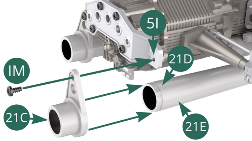
STEP 5
Position the Exhaust outlet bracket (21C) on the Upper and lower right exhaust outlet (21D/21E)) as well as on the Exhaust pipe support (5I), then secure it on the latter using an IM screw.
ASSEMBLY DIAGRAM
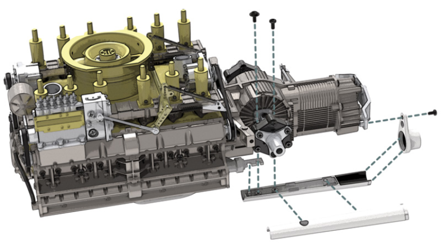
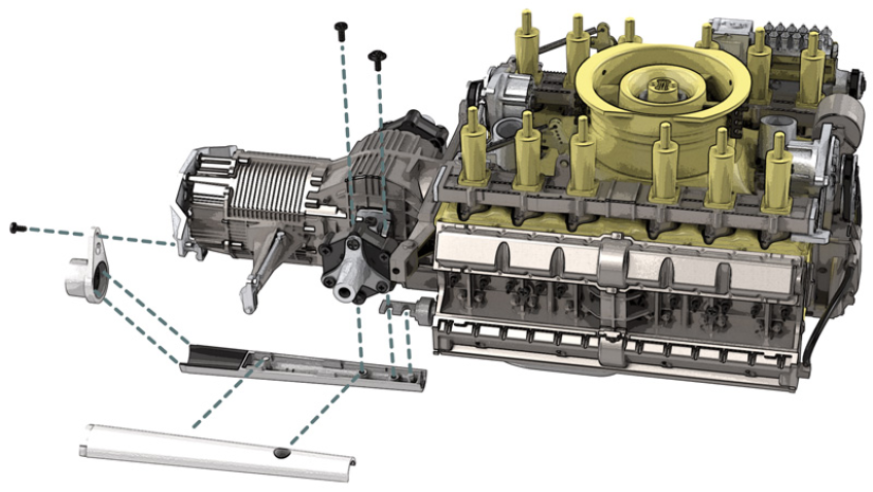
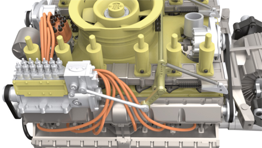
GENERAL VIEW
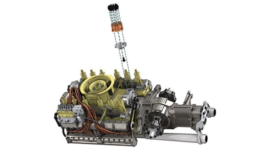
Kit 22
Parts of kit
- 22A Igniter
- 22B Igniter head
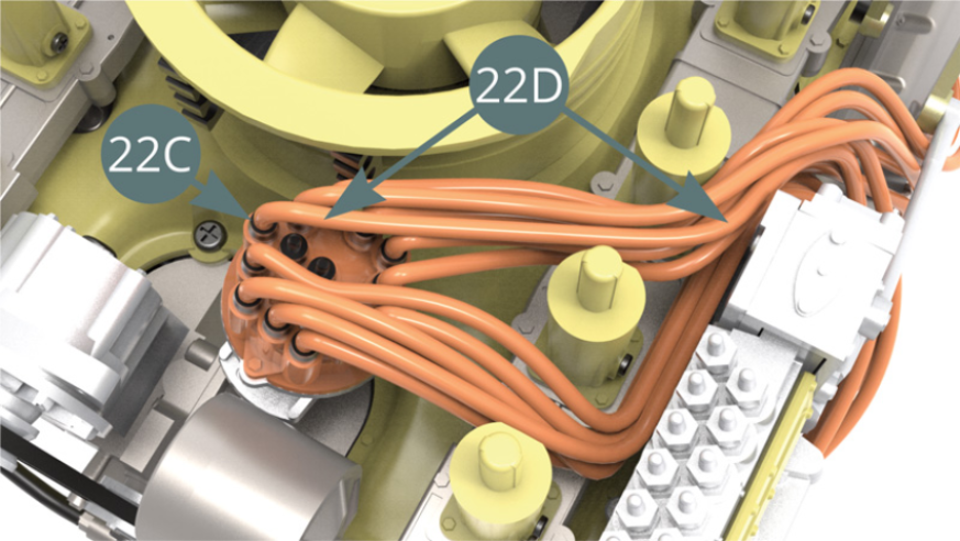
- 22C Ignition wire connector (x 18) / Plastic frame
- 22D Ignition wire (x 12) – on a roll
- AP Screw M 1.7 x 4 mm (x 2)

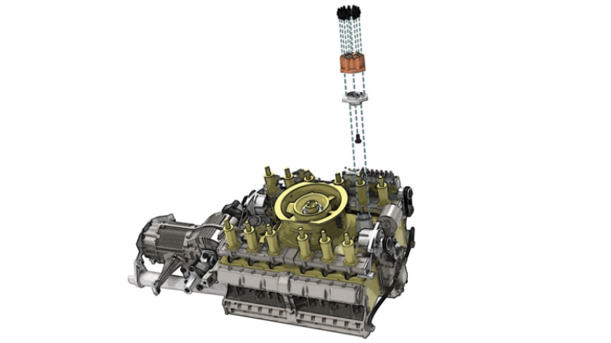
STEP 1
Position the Igniter head (22B) on the Igniter (22A) and secure it using an AP screw.

Detach 14 ignition connectors from the plastic frame - 22C.

STEP 2
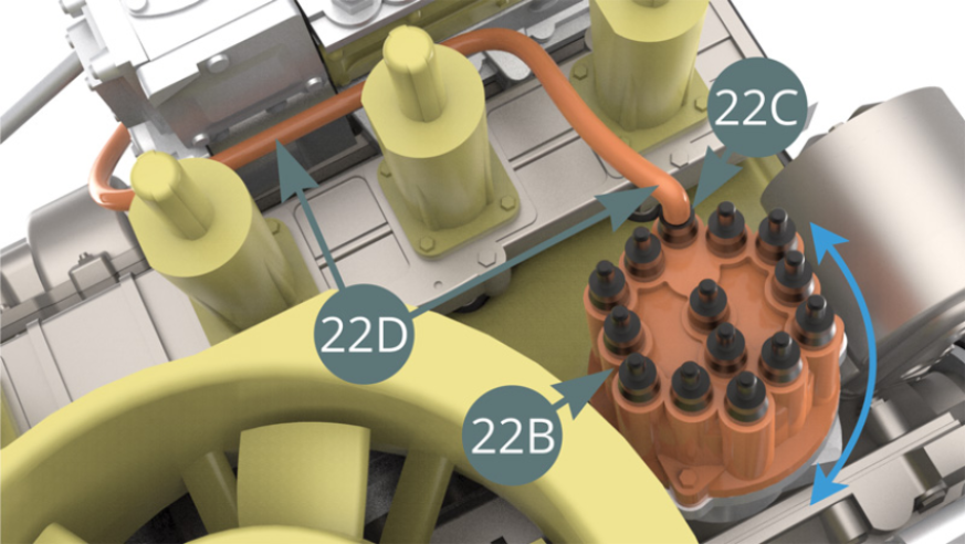
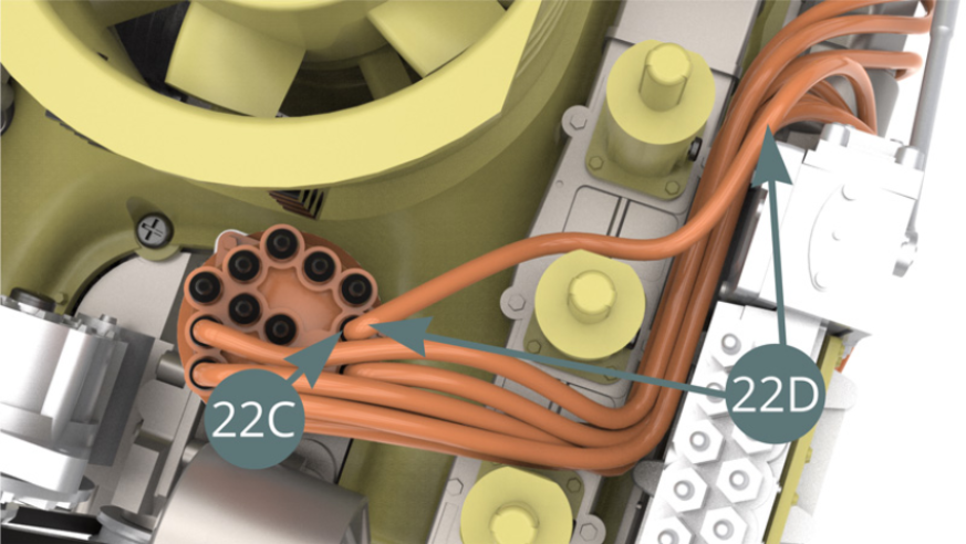
Position 14 ignition wire connectors (22C) on the Igniter head (22B).

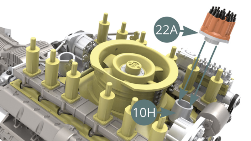
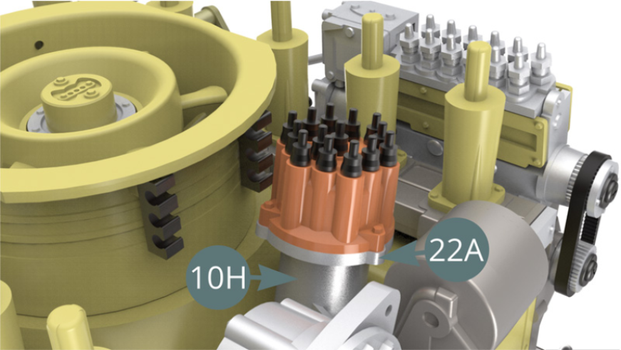
Position the Igniter (22A) on the base of the Distributor (10H), carefully check the right orientation on the illustration below.
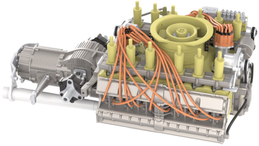
STEP 3
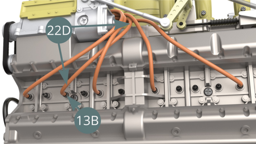
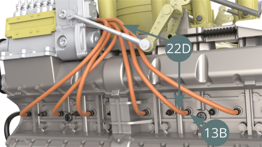
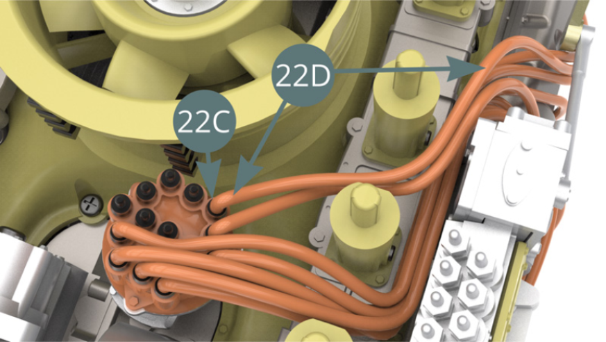
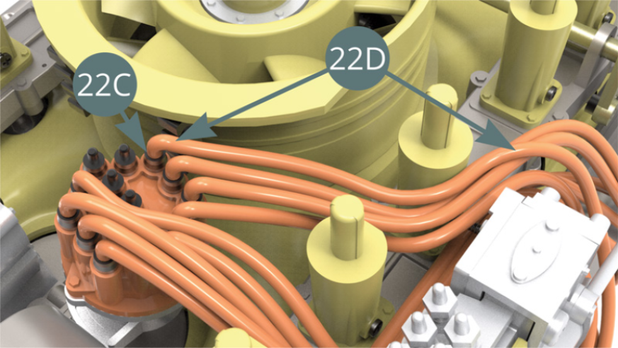
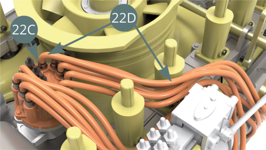
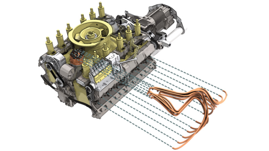
Cut 10 cm ignition wire (first wire) from the Ignition wire roll (22D).

STEP 4
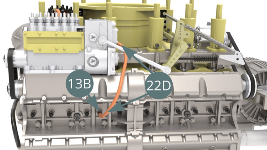
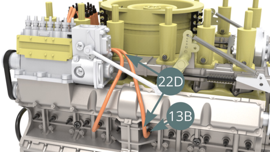
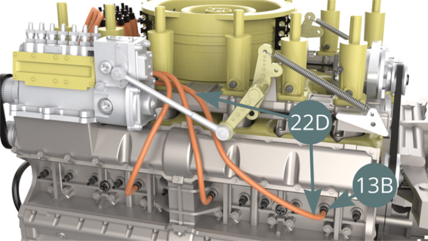
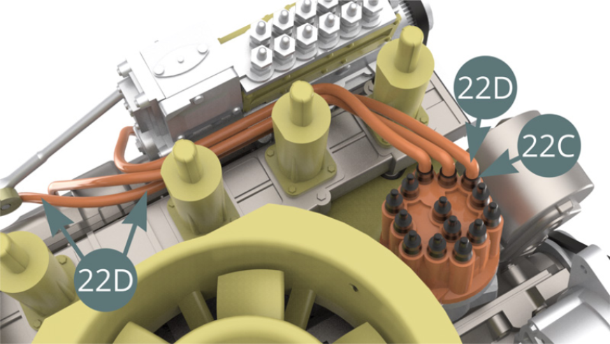
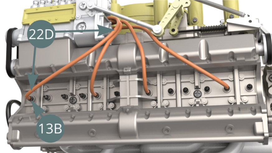
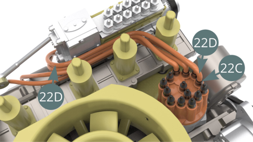
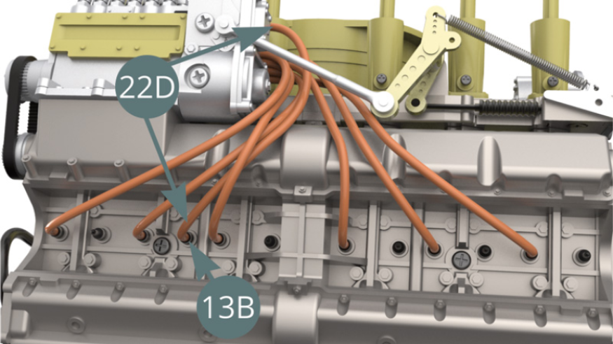
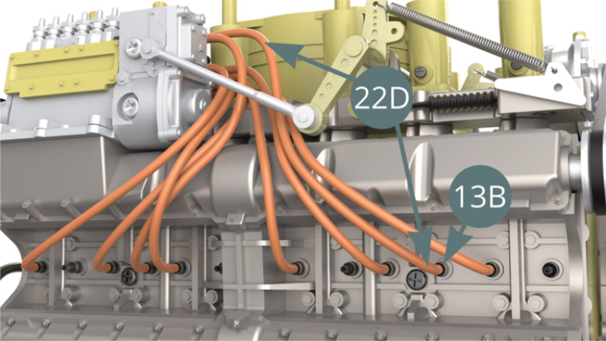
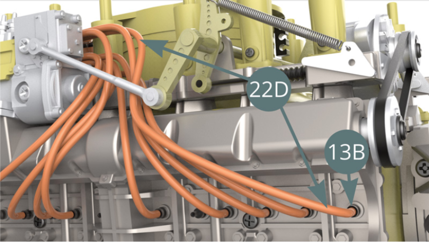
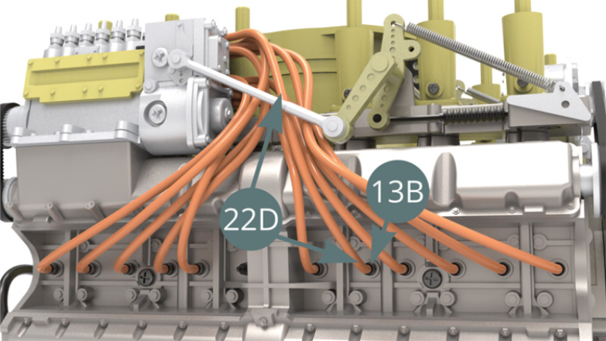
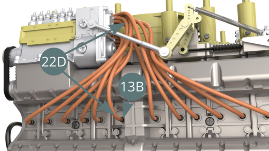
Connect the first ignition wire of 10 cm (22D) to the Spark plug (13B) - illustration below - and to the Connector (22C) - illustration below.Turn the Igniter head (22B) - blue arrow – into the position as shown above.
STEP 5
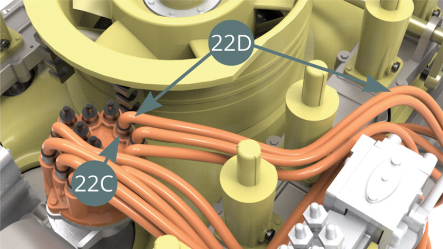
Cut a second ignition wire of 10 cm long from the Ignition wire roll (22D), connect it to the next Spark plug (13B) - illustration below - and to the Connector (22C) – illustration below.

STEP 6
Cut a third ignition wire of 12 cm long from the Ignition wire roll (22D), connect it to the next Spark plug (13B) - illustrations below - and to the Connector (22C) - illustration below.
STEP 7
Cut a fourth ignition wire of 12.5 cm long from the Ignition wire roll (22D), then connect it to the next Spark plug (13B) - illustrations below - and to the Connector (22C) - illustrations below.
STEP 8
Cut a fifth ignition wire of 12 cm long from the Ignition wire roll (22D), then connect it to the next Spark plug (13B) - illustrations below - and to the Connector (22C) - illustration below.
STEP 9
Cut a sixth ignition wire of 12 cm long from the Ignition wire roll (22D), then connect it to the following Spark plug (13B) - illustrations below - and to the Connector (22C) - illustrations below.
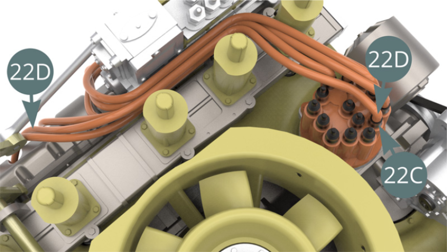
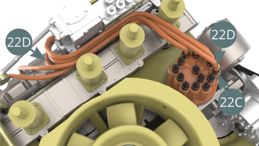
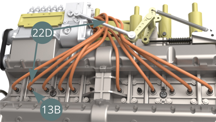
STEP 10
The first six 22D ignition wires are now installed onto the engine.
STEP 11
Cut a seventh ignition wire of 10 cm long from the Ignition wire roll (22D), then connect it to the following Spark plug (13B) - illustrations below - and to the Connector (22C) - illustrations below.
STEP 12
Cut an eighth ignition wire of 10.5 cm long from the Ignition wire roll (22D), then connect it to the following Spark plug (13B) - illustrations below - and to the Connector (22C) - illustrations below.
STEP 13
Cut a ninth ignition wire of 12 cm long from the Ignition wire roll (22D), then connect it to the following Spark plug (13B) - illustrations below - and to the Connector (22C) - illustrations below.
STEP 14
Cut a tenth ignition wire of 11.5 cm long from the Ignition wire roll (22D), then connect it to the following Spark plug (13B) - illustrations below - and to the Connector (22C) - illustrations below.
STEP 15
Cut an eleventh ignition wire of 10.5 cm long from the Ignition wire roll (22D), then connect it to the following Spark plug (13B) - illustrations below - and to the Connector (22C) - illustrations below.
STEP 16
Cut a twelfth ignition wire of 10.5 cm long from the Ignition wire roll (22D), then connect it to the following Spark plug (13B) - illustrations below - and to the Connector (22C) - illustrations below.
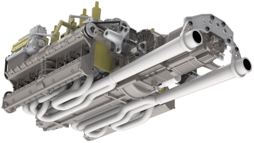
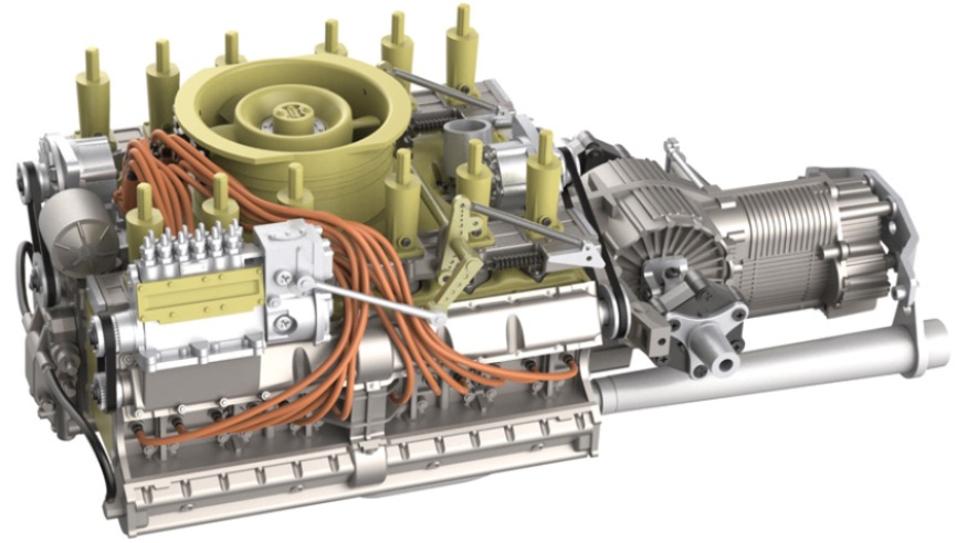
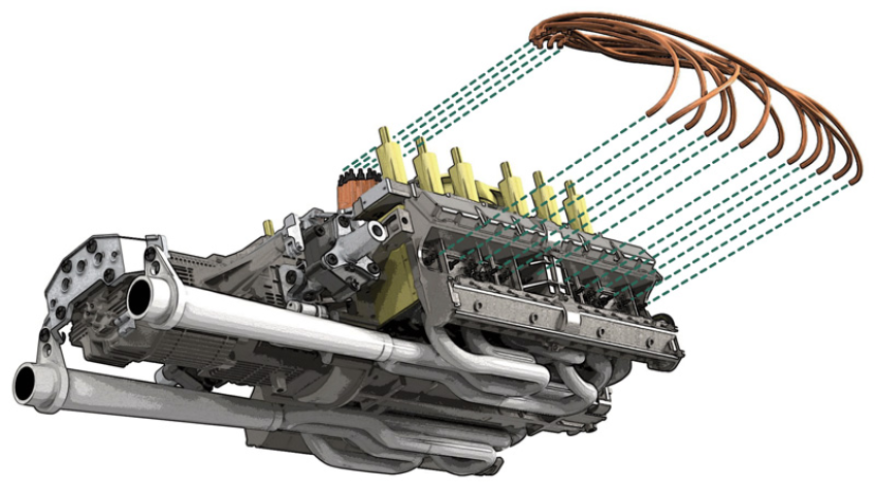
ASSEMBLY DIAGRAM
GENERAL VIEW
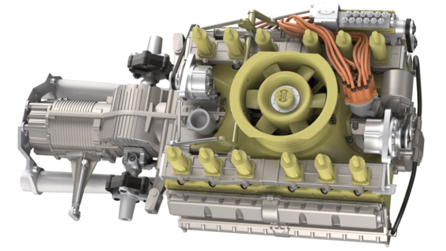
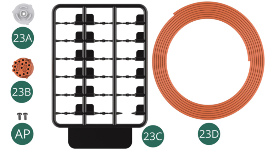
Kit 23
Parts of kit
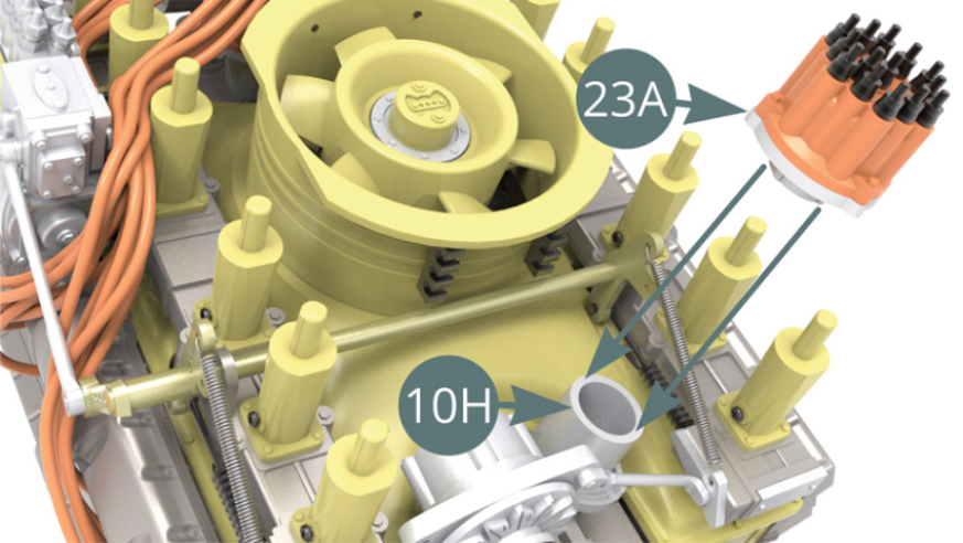
- 23A Igniter
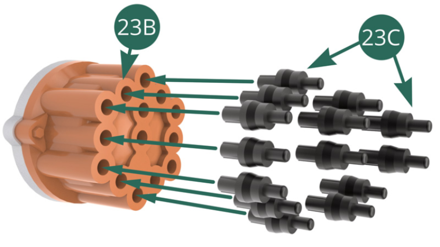
- 23B Igniter head
- 23C Ignition wire connector (x 17) / Plastic frame
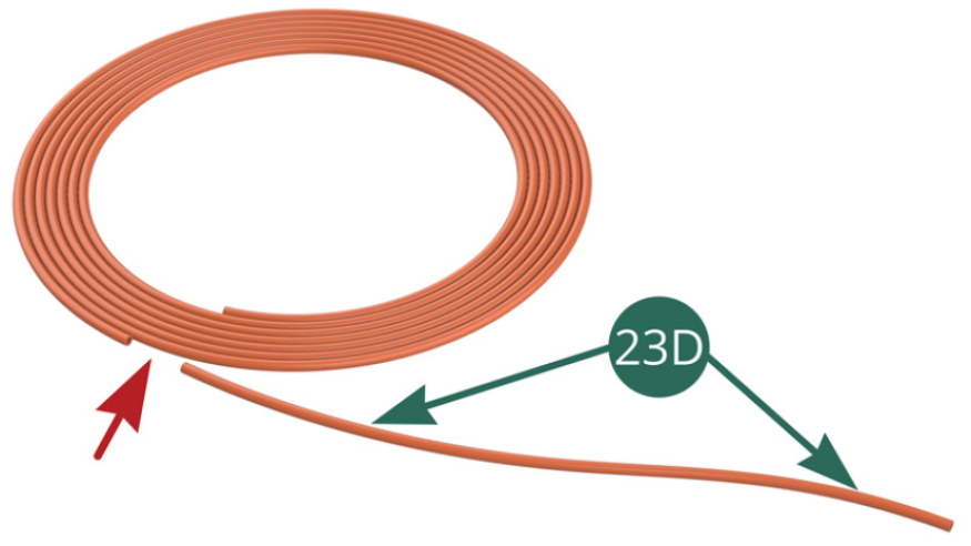
- 23D Ignition wire (x 12) - on a roll
- AP Screw M 1.7 x 4 mm (x 2)
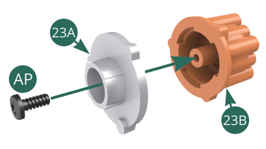
STEP 1
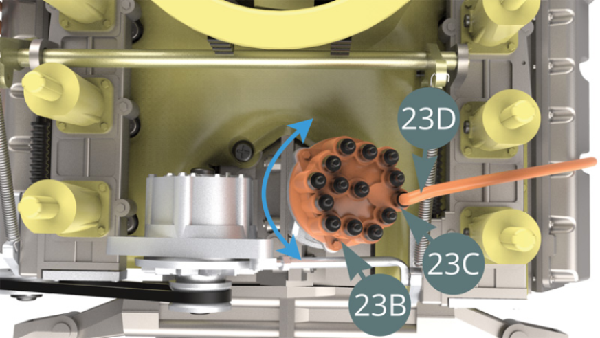
Position Igniter head (23B) on the Igniter (23A)) and secure it using an AP screw.
Detach 14 ignition connectors from the plastic frame - 23C.
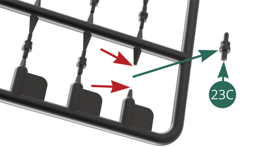
STEP 2
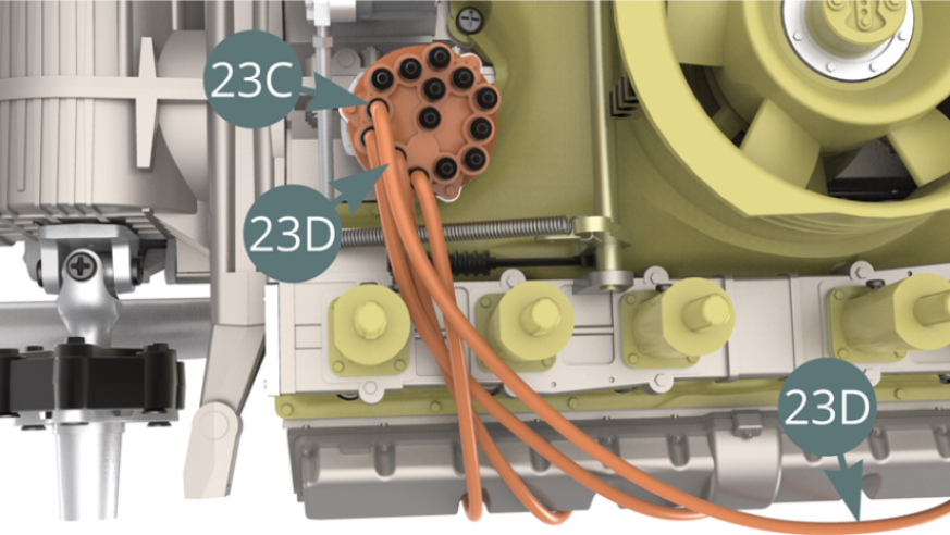
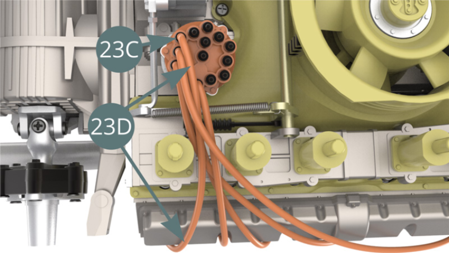
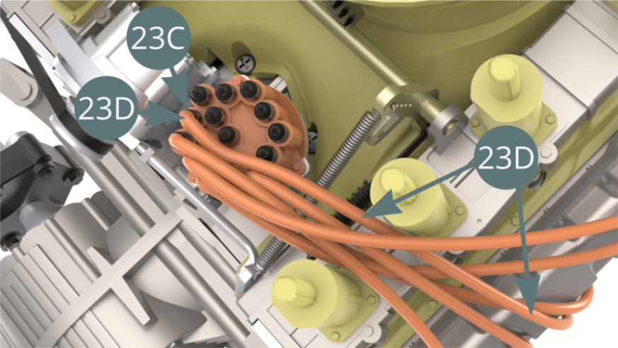
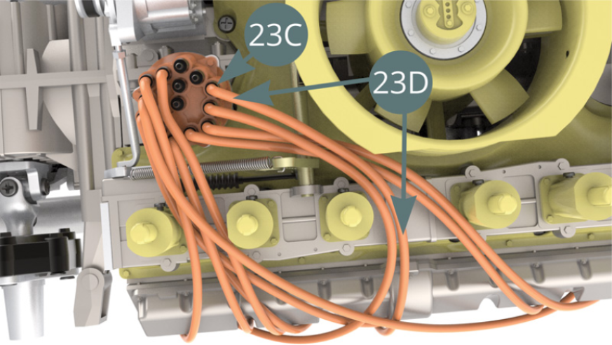
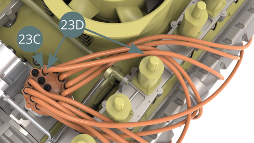
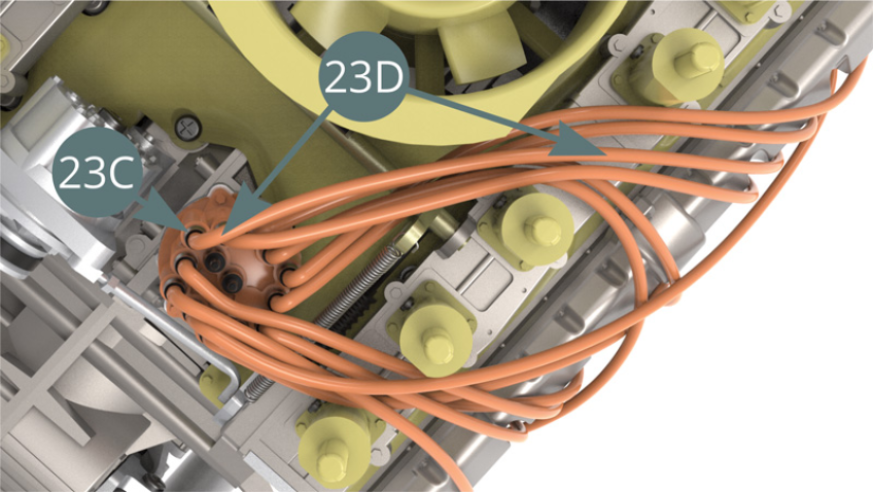
Position 14 ignition wire connectors (23C) on the Igniter head (23B).
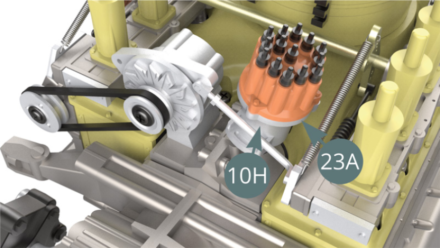
Position the Igniter (23A) on the base of the Distributor (10H), carefully check the right orientation on the illustration.
STEP 3
Cut 7.5 cm ignition wire (first wire) from the Ignition wire roll (23D).
STEP 4
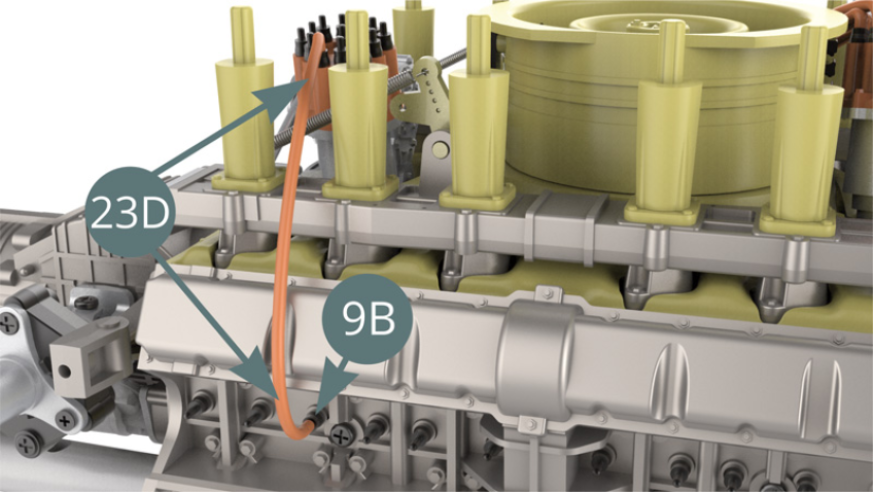
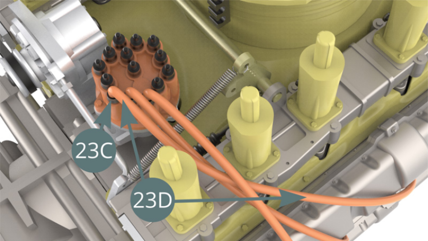
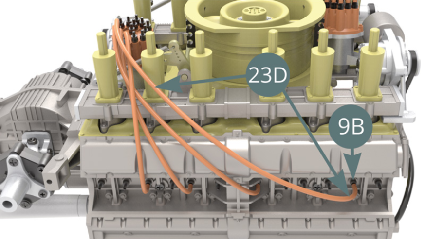
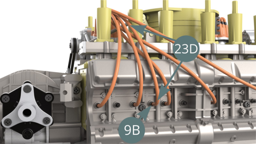
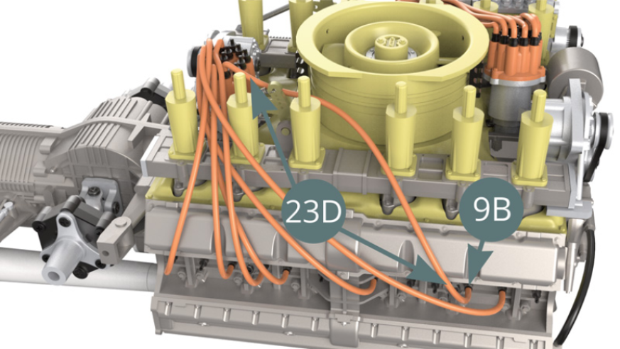
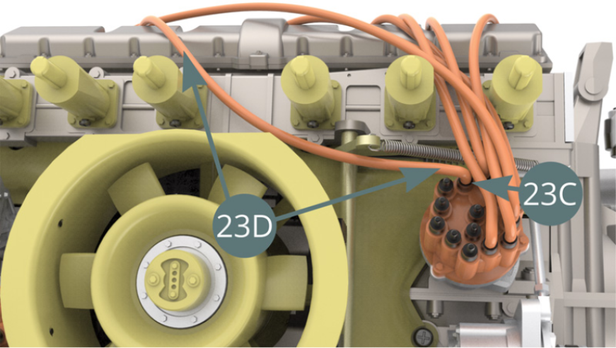
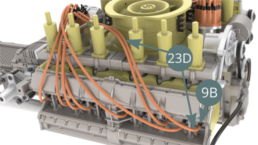
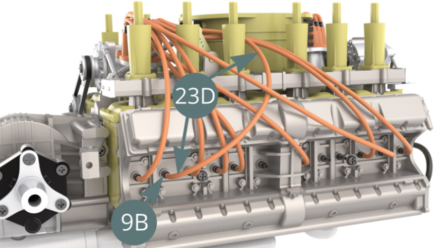
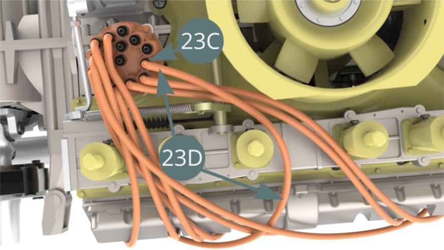
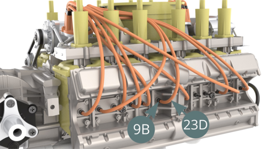
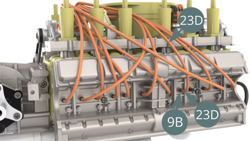
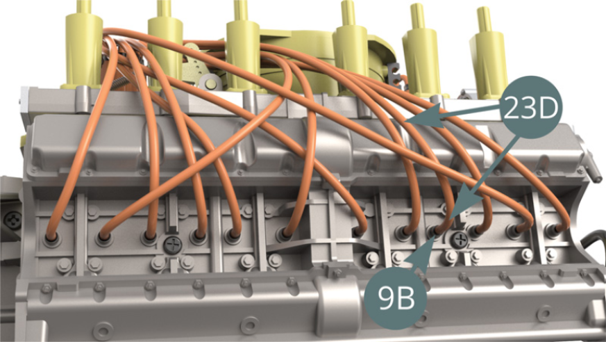
Connect the first ignition wire of 7.5 cm (23D) to the Spark plug (9B) - illustration below - and to the Connector (23B) – illustration below. Turn the Igniter head (23B) - blue arrow - into the position as shown above.
STEP 5
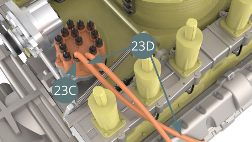
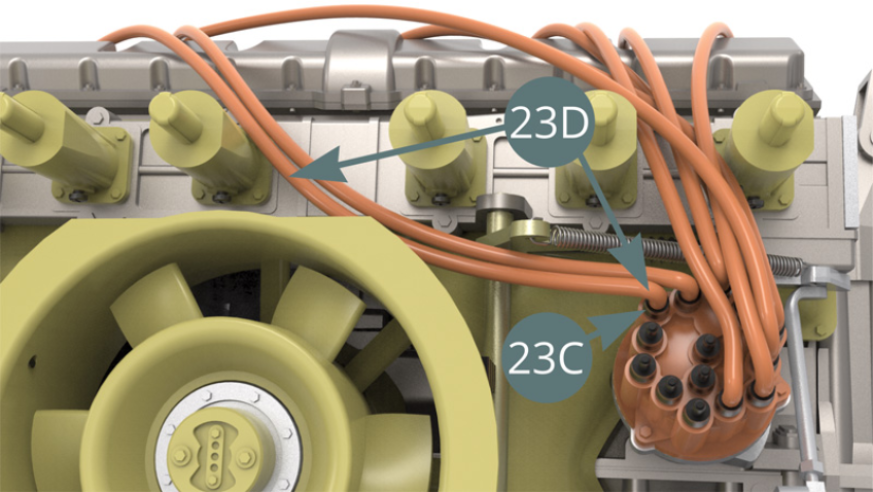
Cut a second ignition wire of 8.2 cm long the Ignition wire roll (23D), connect it to the Spark plug (9B) - illustration below - and to the Connector (23C) – illustration below.

STEP 6
Cut a third ignition wire of 9.8 cm long from the Ignition wire roll (23D), connect it to the next Spark plug (9B) - illustration below - and to the Connector (23C) – illustration below.
STEP 7
Cut a fourth ignition wire of 12 cm long from the Ignition wire roll (23D), connect it to the next Spark plug (9B) - illustration below - and to the Connector (23C) – illustration below.
STEP 8
Cut a fifth ignition wire of 8.5 cm long from the Ignition wire roll (23D), connect it to the next Spark plug (9B) - illustration below - and to the Connector (23C) – illustration below.
STEP 9
Cut a sixth ignition wire of 9 cm long from the Ignition wire roll (23D), connect it to the next Spark plug (9B) - illustration below - and to the Connector (23C) – illustration below.
STEP 10
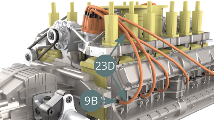
The first six 23D ignition wires are now installed onto the engine.
STEP 11
Cut a seventh ignition wire of 10.5 cm long from the Ignition wire roll (23D), connect it to the next Spark plug (9B) - illustration below - and to the Connector (23C) – illustration below.
STEP 12
Cut an eighth ignition wire of 11.5 cm long from the Ignition wire roll (23D), connect it to the next Spark plug (9B) - illustration below - and to the Connector (23C) – illustration below.
STEP 13
Cut a ninth ignition wire of 10.5 cm long from the Ignition wire roll (23D), connect it to the next Spark plug (9B) - illustration below - and to the Connector (23C) – illustration below).
STEP 14
Cut a tenth ignition wire of 9.5 cm long from the Ignition wire roll (23D), connect it to the next Spark plug (9B) - illustration below - and to the Connector (23C) – illustration below).
STEP 15
Cut an eleventh ignition wire of 10.5 cm long from the Ignition wire roll (23D), connect it to the next Spark plug (9B) - illustration below - and to the Connector (23C) – illustration below).
STEP 16
Cut a twelfth ignition wire of 11 cm long from the Ignition wire roll (23D), connect it to the next Spark plug (9B) - illustration below - and to the Connector (23C) – illustration below).
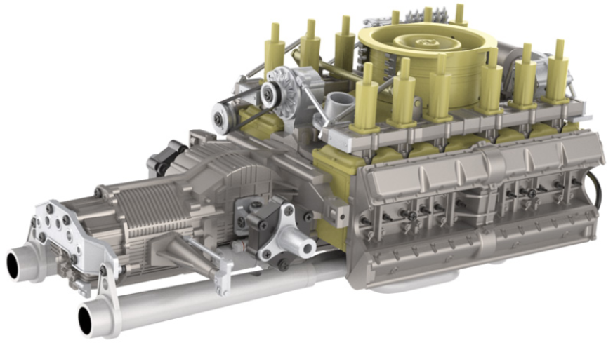
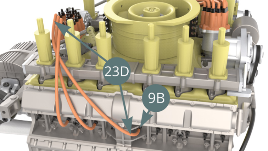
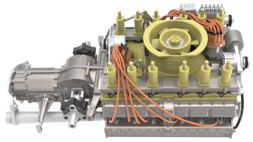
ASSEMBLY DIAGRAM
GENERAL VIEW
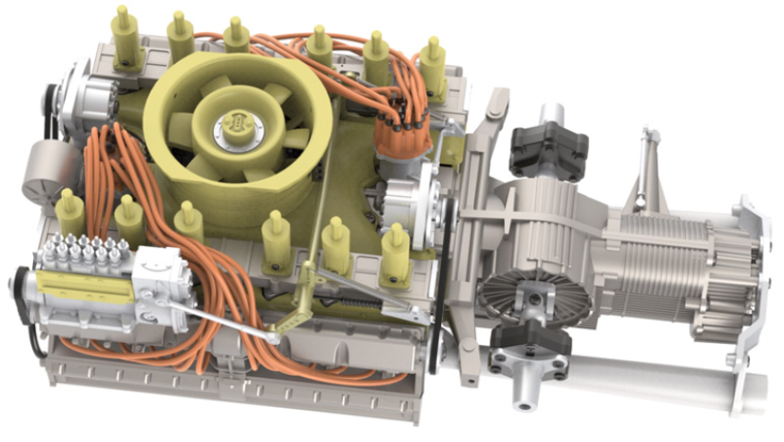
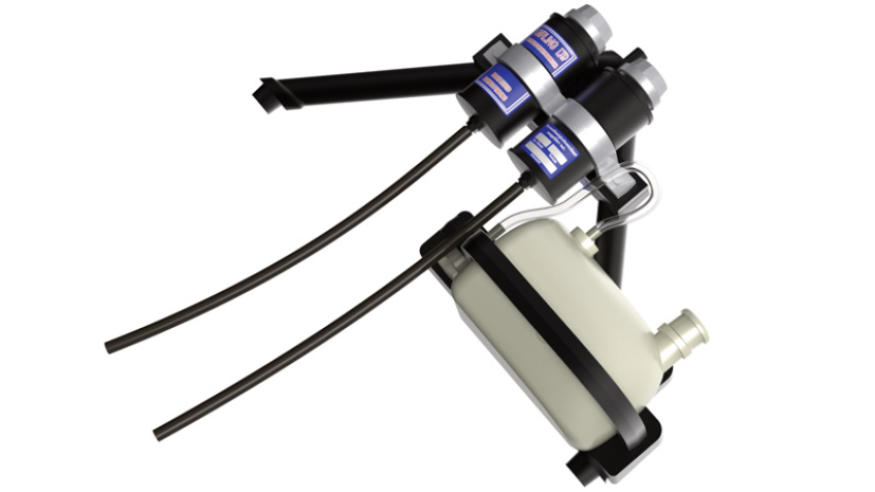
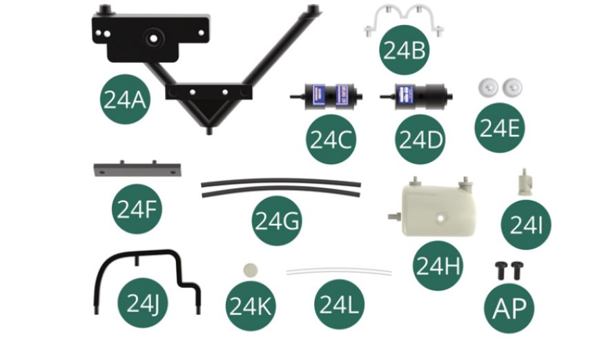
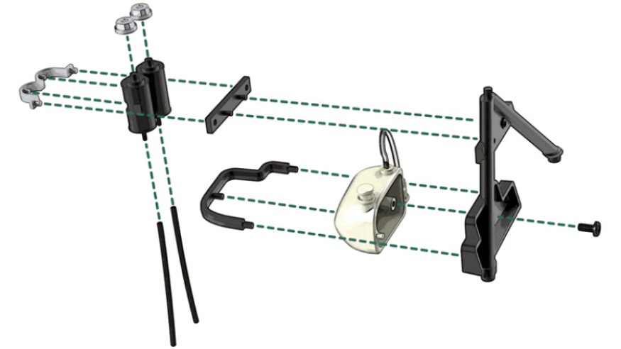
Kit 24
Parts of kit
- 24A V-frame
- 24B Collar link
- 24C Brake fluid reservoir
- 24D Brake fluid reservoir
- 24E Cap (x 2)
- 24F Support
- 24G Brake Fluid Hose (x 2)
- 24H Windshield washer reservoir
- 24I Windshield washer pump
- 24J Clip
- 24K Cap
- 24L Windshield washer fluid hose
- AP Screw M 1.7 x 4 mm (x 2)
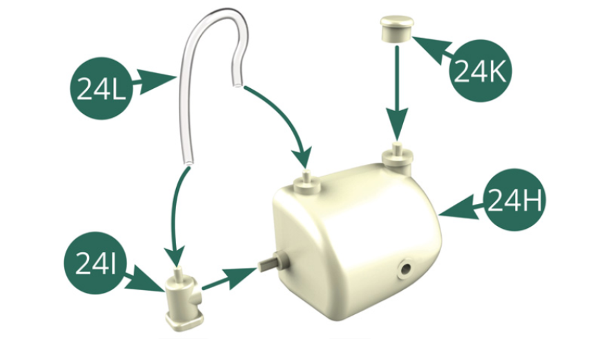
STEP 1
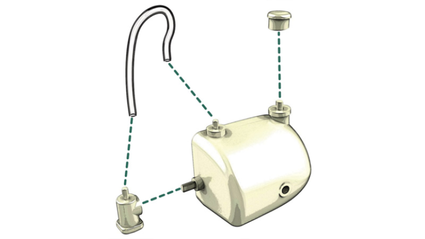
Position the Cap (24K) onto the Washer reservoir (24H). Position the Windshield washer pump (24I) on Washer reservoir (24H), then connect the Washer fluid hose (24L) to the Washer pump (24I) and Windshield washer reservoir (24H).
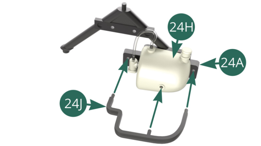
Position the Windshield washer reservoir (24H) on the V-frame (24A) and secure with an AP screw.

STEP 2
Position the Clip (24J) on the V-frame (24A) and on the Windshield washer reservoir (24H).
Position Cap (24E) on the Brake fluid reservoir (24C), then connect the Hose (24G). Position the Tank (24C) on the attachment Collar (24B).
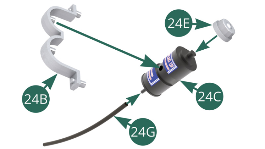
STEP 3
Position the Cap (24E) on the Brake fluid tank (24D, then connect the Fluid hose (24G). Position Brake fluid reservoir (24C) on Clamp (24B).
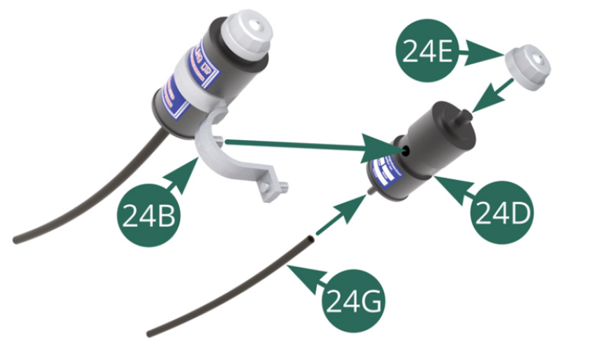
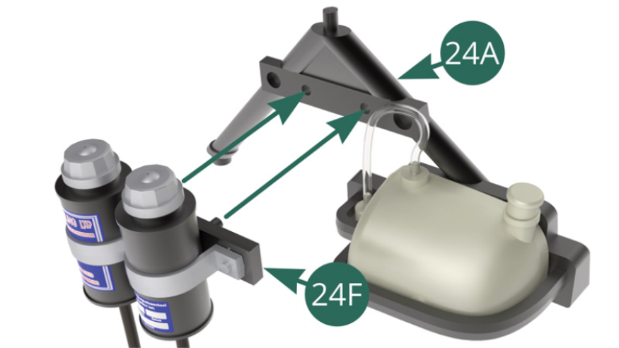
Position Clamp (24B) on Support (24F).

STEP 4
Position Support (24F) on the V-frame (24A) – illustrations below.
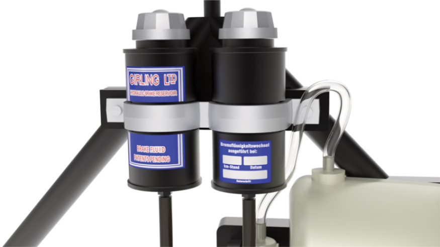
ASSEMBLY DIAGRAM
GENERAL VIEW