English
 français
 Deutsch
 español
 italiano
 português


Box 7
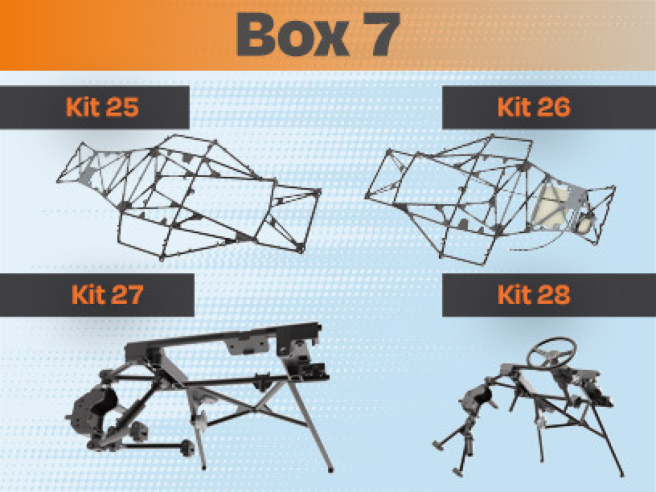
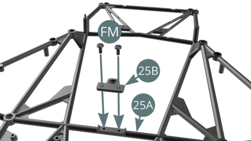
Kit 25
Parts of kit
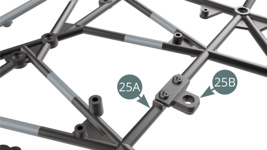
- 25A Lower frame
- 25B Front engine mount
- FM Screw M 1.7 x 4 mm (x 3)

STEP 1
Position the front engine mount 25B on the lower frame 25A and fix it with two FM screws (illustration opposite).
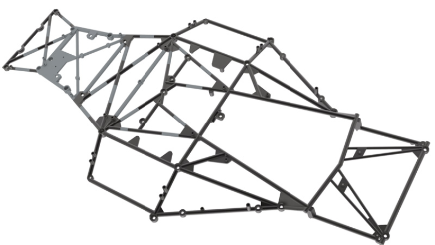
ASSEMBLY DIAGRAM
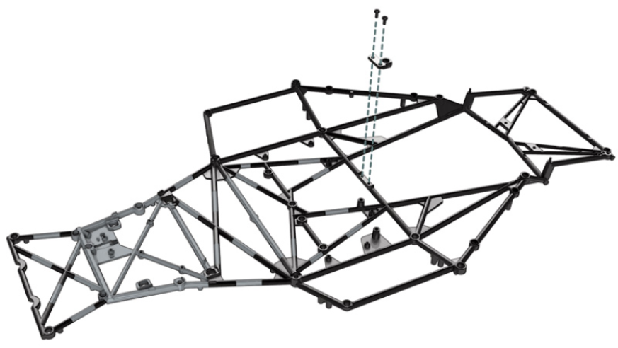
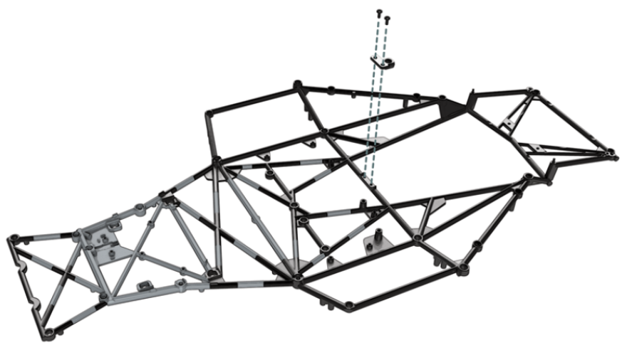
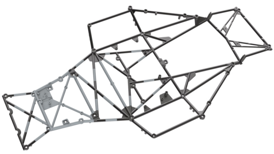
GENERAL VIEW
Kit 26
Parts of kit
- 26A Footrest
- 26B Rod
- 26C Bottom bracket
- 26D Throttle pedal
- 26E Clutch pedal
- 26F Brake pedal
- 26G Pedal bracket
- 26H Master cylinder
- 26I Tappet (x 2)
- 26J Clutch cable
- 26K Brake light switch cable
- AP Screw M 1.7 x 4 mm (x 2)
- GP Screw M 1.2 x 5 mm (x 2)
- KP Screw M 1.2 x 9.5 mm (x 2)
- IM Screw M 1.7 x 3.5 mm (x 3)
- KM Screw M 1.7 x 3 x 5 mm (x 3)

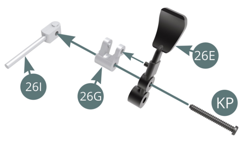
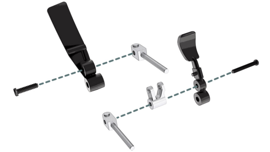
STEP 1
Position a KP screw in a 26I tappet by first passing it through the 26E clutch pedal and then the 26G bracket.
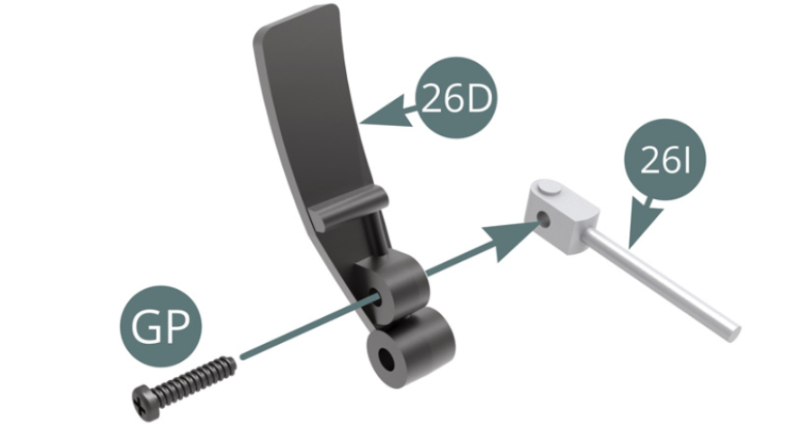
Position a GP screw in a 26I tappet by first passing it through the 26D Throttle pedal.
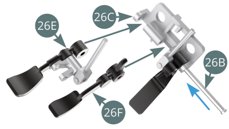
STEP 2
Position the throttle pedal 26D on the pedal bracket 26C and lock it with the 26B rod.
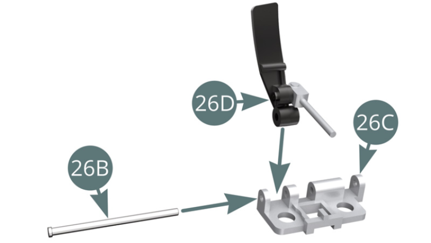
Position the brake pedal 26F and the clutch pedal 26E, one after the other, on the bottom bracket 26C and lock them successively by advancing the 26B rod (blue arrow).
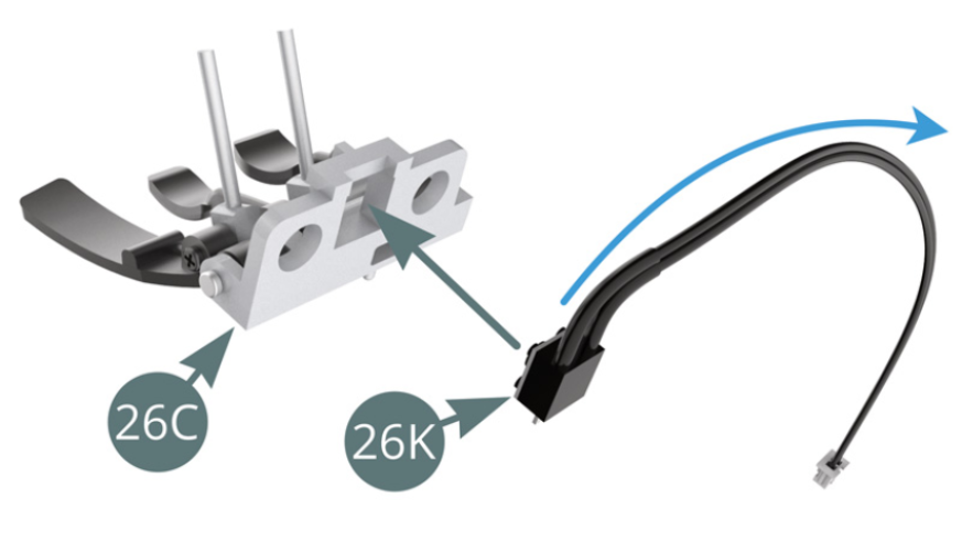
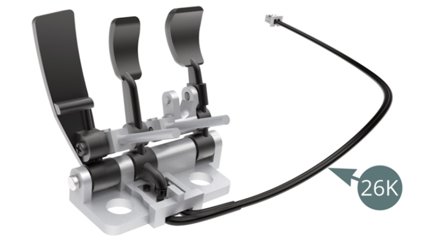
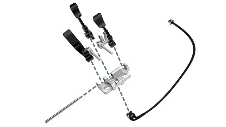
STEP 3
Fold the 26K brake light switch cable to the side (blue arrow) and position the switch into the slot provided under the 26C bottom bracket.
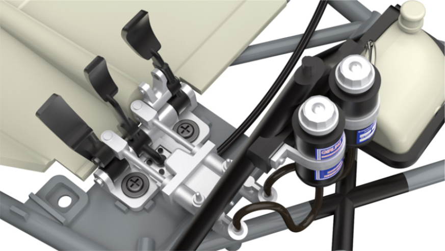
Pedal assembly
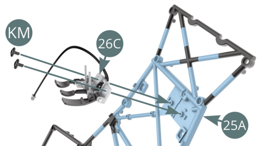
STEP 4
Position the 26C bottom bracket on the 25A lower frame and secure it with two KM screws.
Crankset installed on the frame

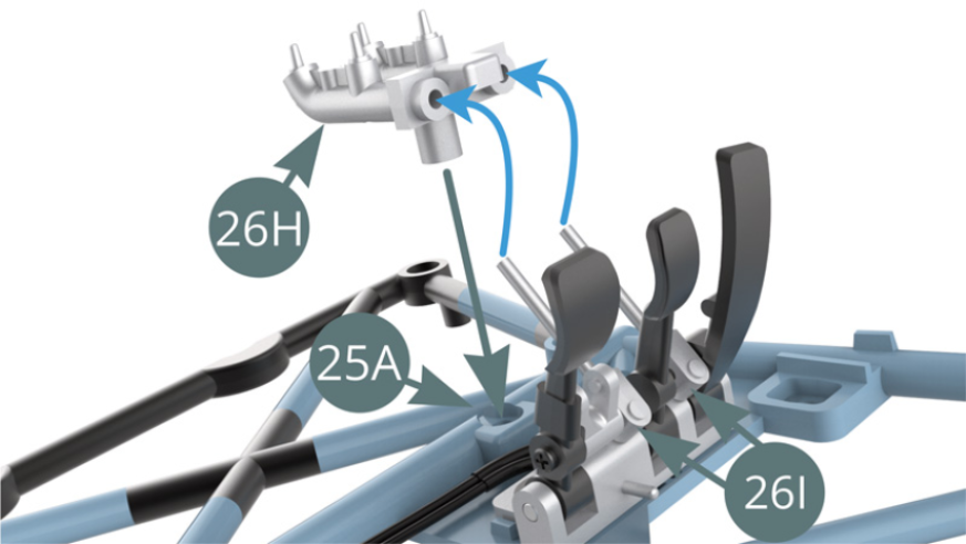
STEP 5
Position the master cylinders 26H on the lower frame 25A and, at the same time, insert the two 26I tappets into their respective master cylinder housings 26H (blue arrow).
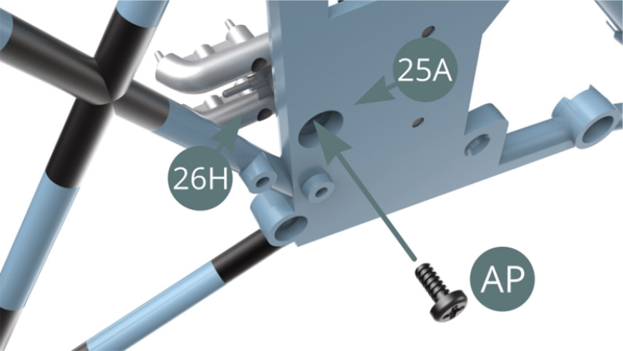
STEP 6
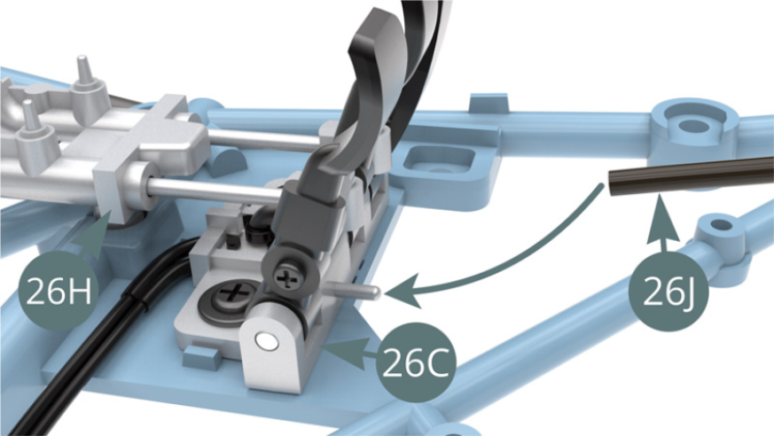
Attach the master cylinders 26H to the lower frame 25A with an AP screw.
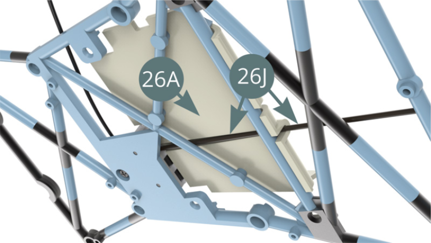
Position the clutch cable 26J on the nozzle at the rear of the bottom bracket 26C.
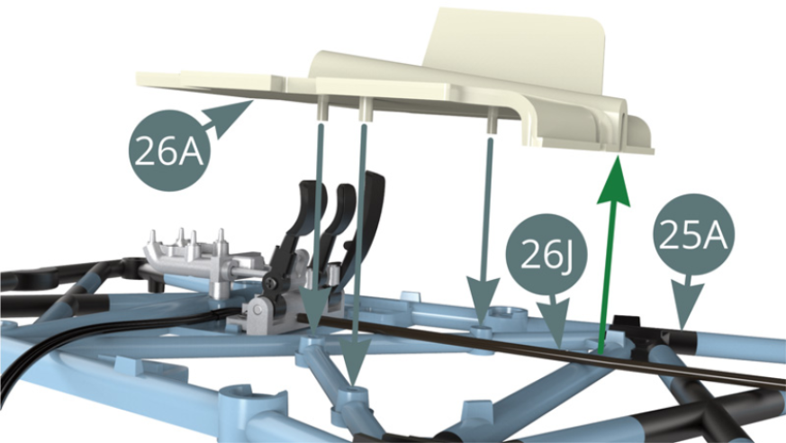
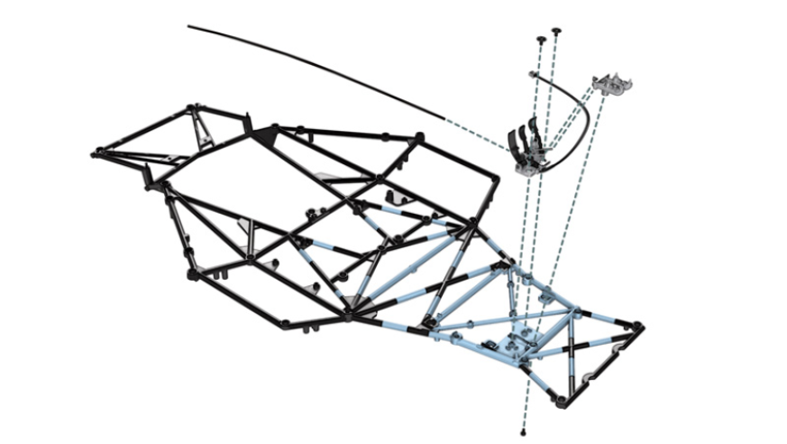
STEP 7
Position the footrest 26A on the lower frame 25A using the three lugs provided. Pass the clutch cable 26J through the slot indicated by the green arrow (see illustrations opposite).
STEP 8
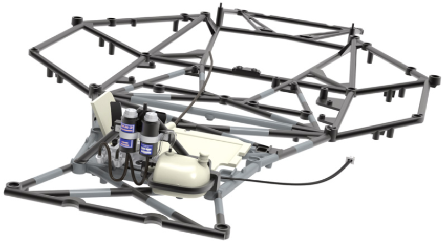
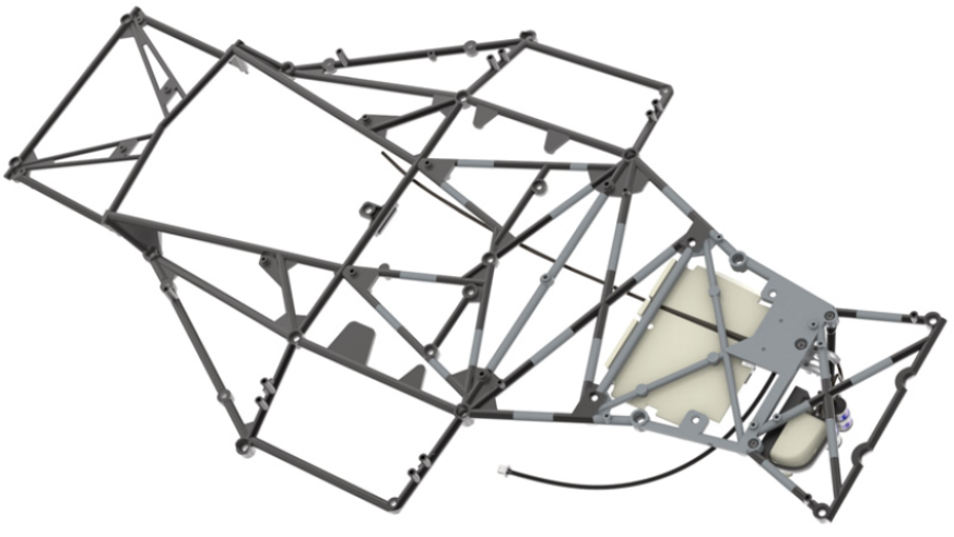
Footrest 26A installed on the chassis

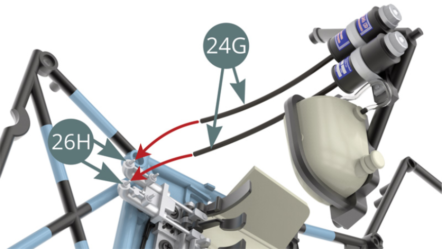
Position the 24G brake fluid hose nozzles on the front of the 26H master cylinders (continued on the following illustration).
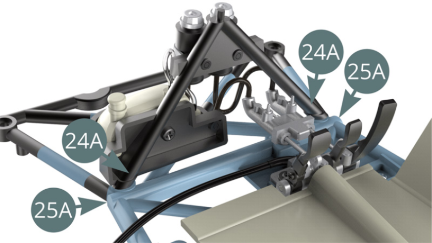
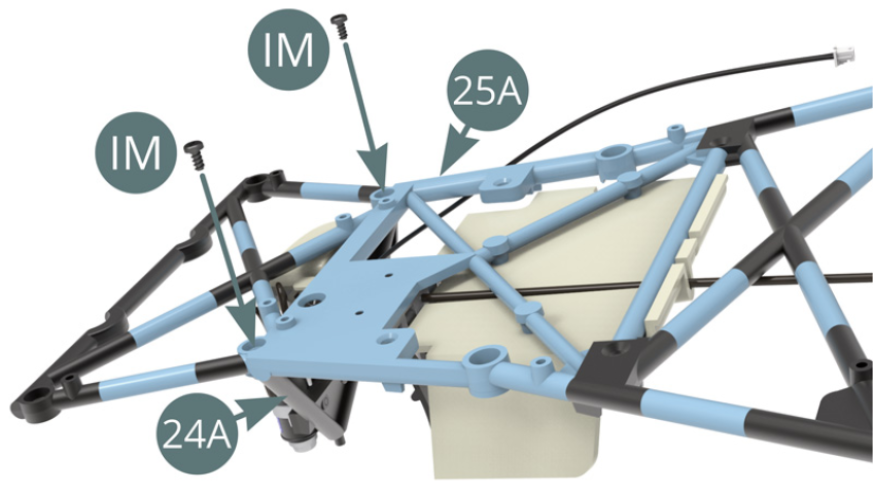
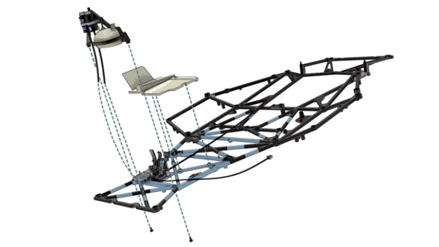
STEP 9
Continue by positioning the 24A V frame on the lower frame 25A, then fix it from below with two IM screws (illustrations opposite).
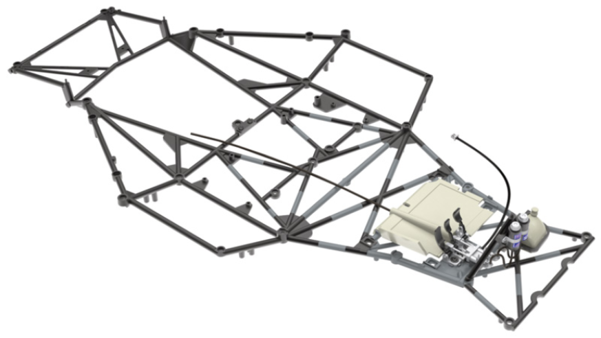
ASSEMBLY DIAGRAM
GENERAL VIEW
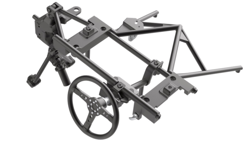
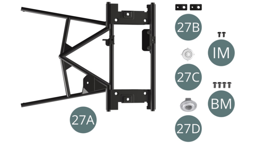
Kit 27
Parts of kit
- 27A Dashboard Frame
- 27B Bracket (x 2)
- 27C Windscreen wiper control
- 27D Horn
- IM Screw M 1.7 x 3.5 mm (x 2)
- BM Screw M 2 x 4 mm (x 4)
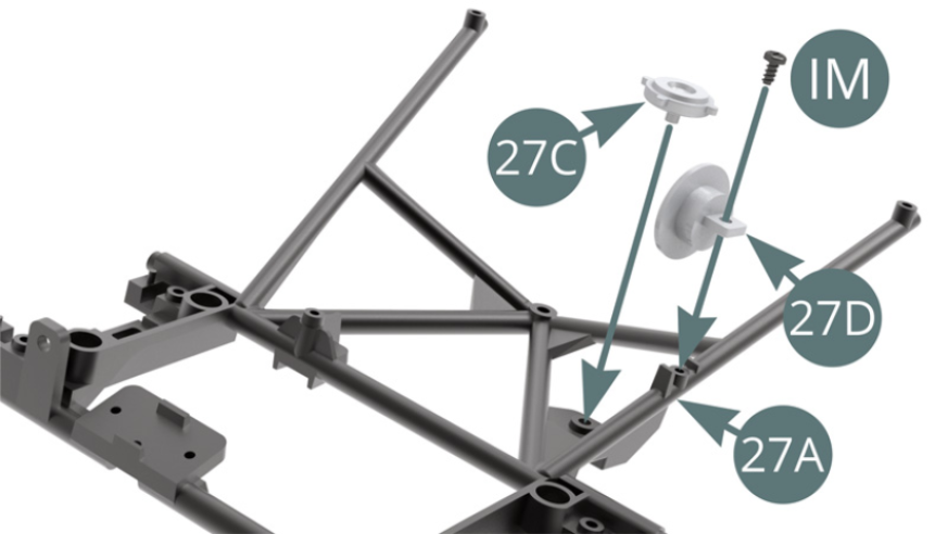
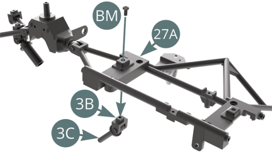
STEP 1
Position the 27C wiper control and 27D horn on the 27A dashboard frame and secure the horn with an IM screw.
Position the upper swing arm 3A on the dashboard frame 27A.
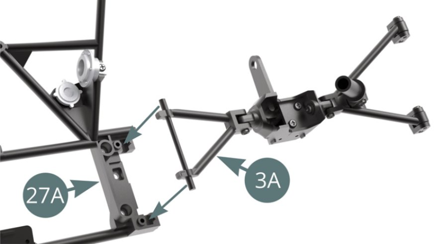
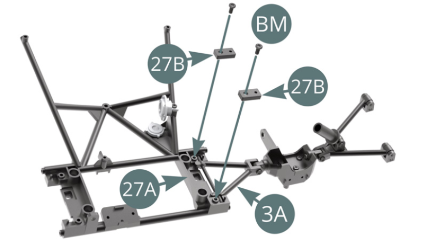
STEP 2
Attach the upper swingarm 3A to the dashboard frame 27A using the brackets 27B and two BM screws.
Position the 3B shock bracket and 3C piston on the 27A dashboard frame, and secure it with a BM screw.
ASSEMBLY DIAGRAM
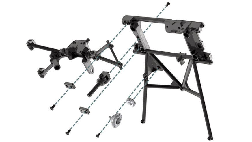
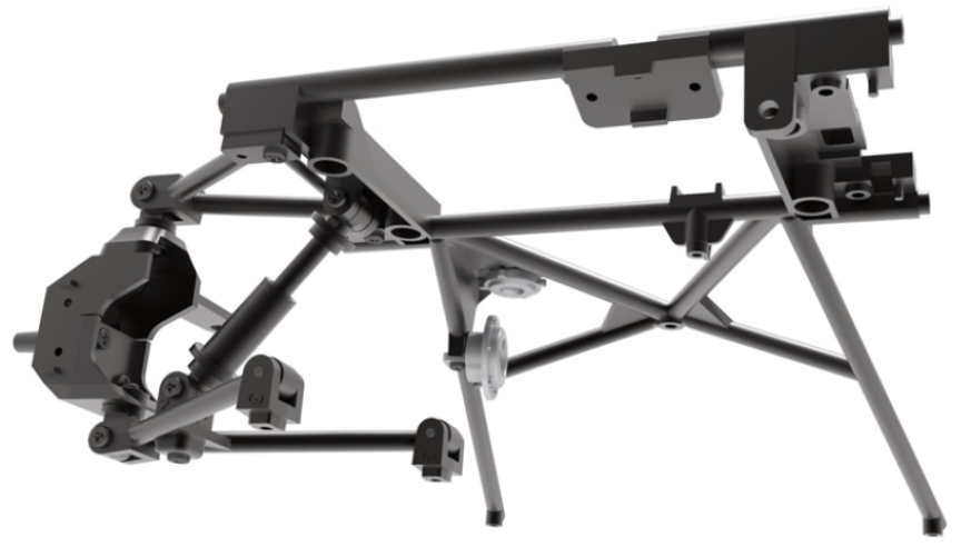
GENERAL VIEW
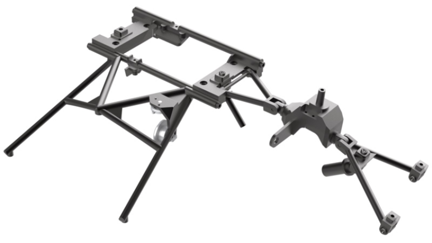
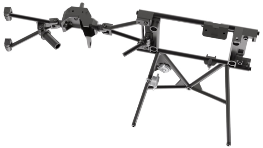
View of the left front suspension in its future mounting position
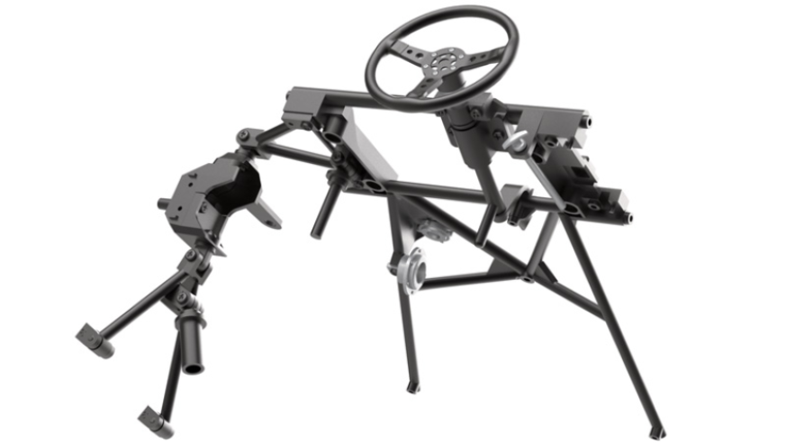
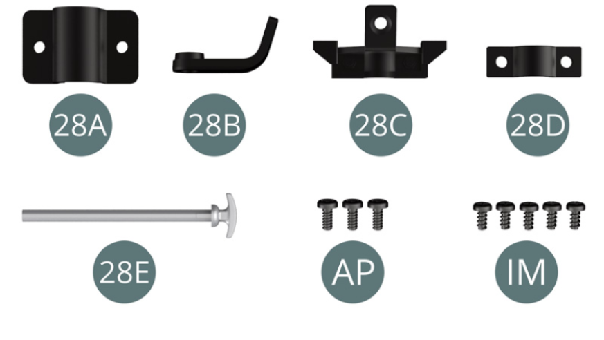
Kit 28
Parts of kit
- 28A Attachment
- 28B Support
- 28C Support
- 28D Attachment
- 28E Fire extinguisher pull
- AP Screw M 1.7 x 4 mm (x 3)
- IM Screw M 1.7 x 3.5 mm (x 5)
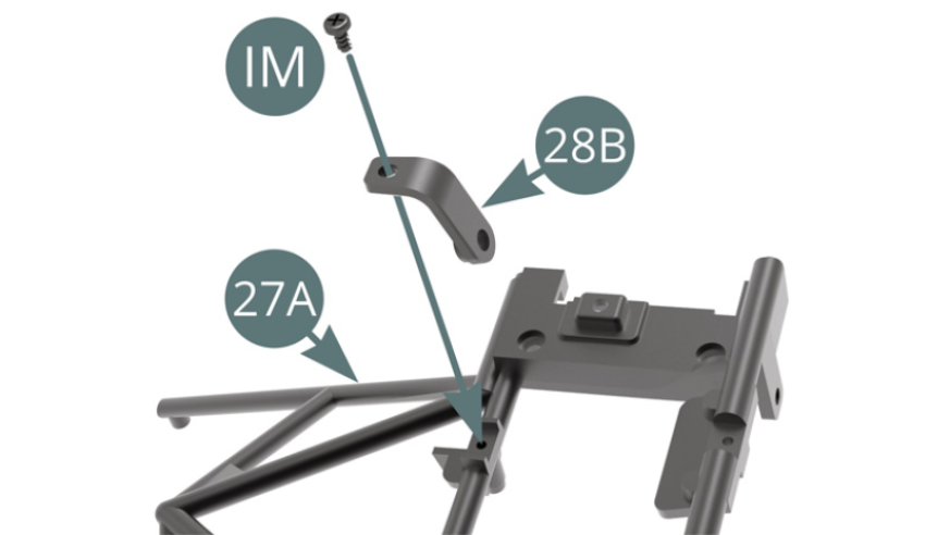
STEP 1
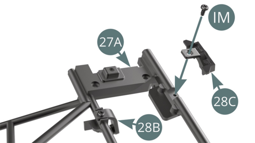
Position the 28B support on the 27A dashboard frame and secure it with an IM screw.
Position the 28C support on the 27A dashboard frame and secure it with an IM screw.
STEP 2
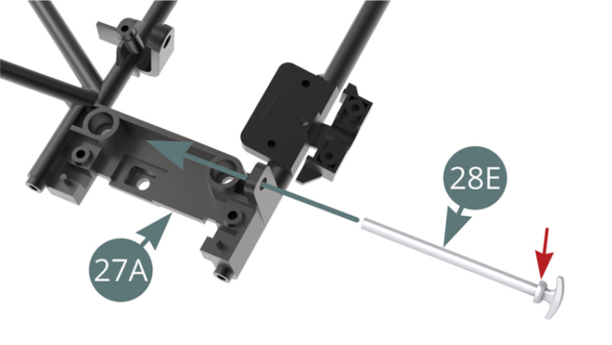
Position the 28E fire extinguisher pull on the 27A dashboard frame.
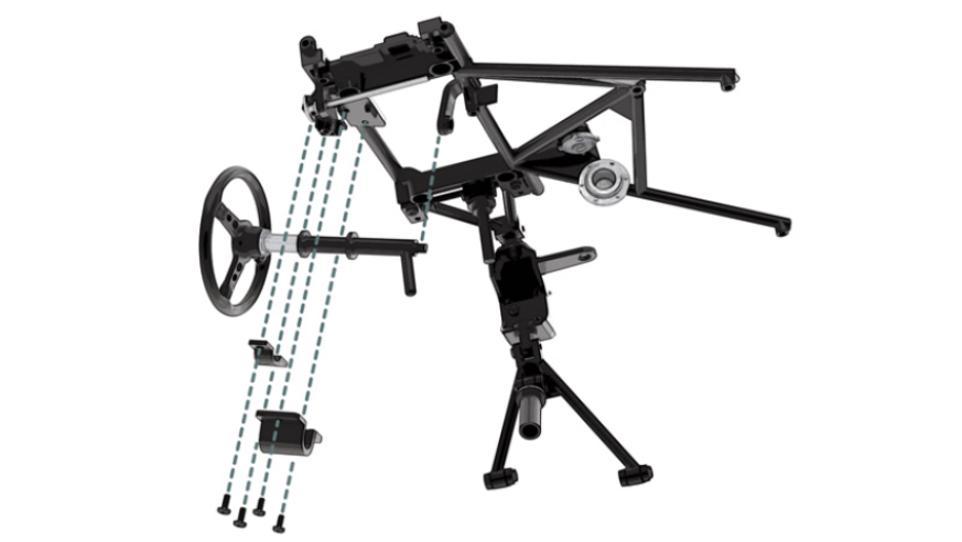
STEP 3
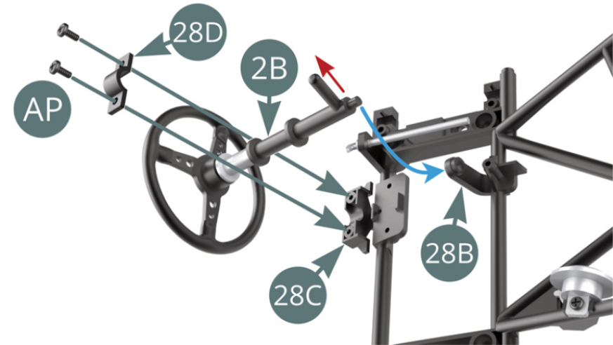
Position the end of 2B steering column on 28B support (blue arrow) and secure it to support 28C using attachment 28D and two AP screws. Check the orientation of the axle at the end of steering column 2B (red arrow).
STEP 4
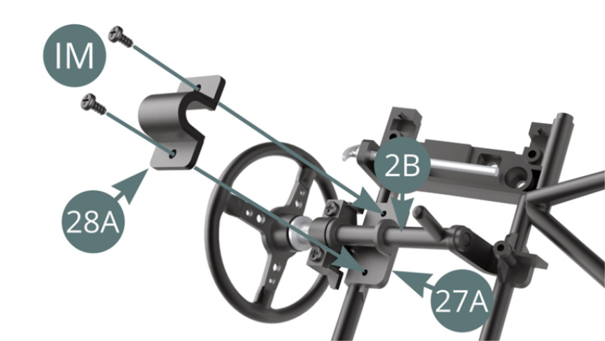
Attach the 2B steering column to the 27A dashboard frame using 28A attachment and two screws IM.
ASSEMBLY DIAGRAM
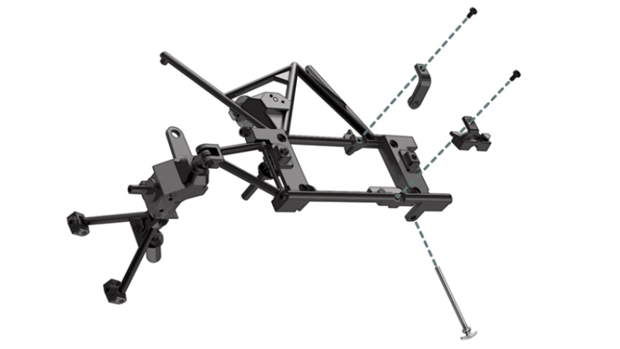
GENERAL VIEW