English
 français
 Deutsch
 español
 italiano
 português


Box 8
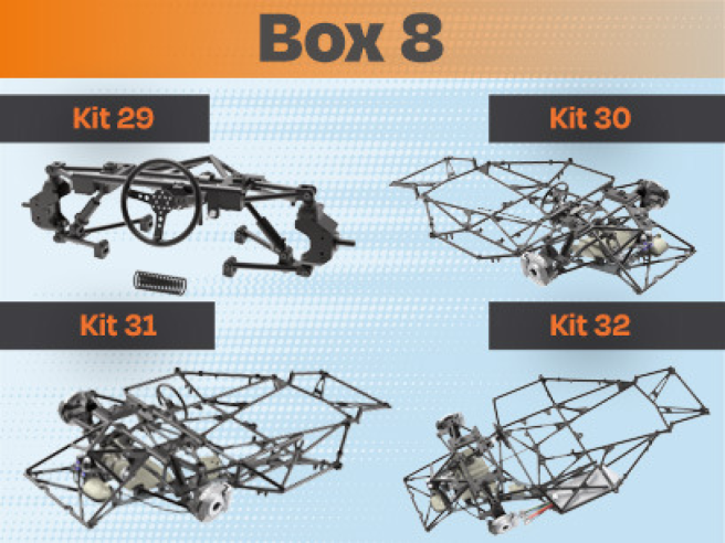
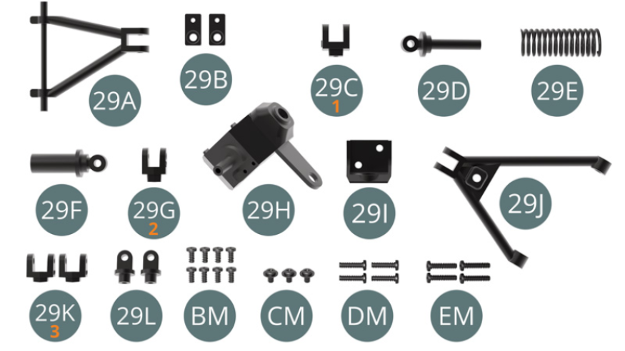
Kit 29
Parts of kit
- 29A Upper front wishbone
- 29B Bracket (x 2)
- 29C Shock absorber upper support (marked 1)
- 29D Shock piston
- 29E Shock spring
- 29F Shock cylinder
- 29G Lower shock absorber support (marked 2)
- 29H Hub carrier top
- 29I Lower hub carrier
- 29J Lower front wishbone
- 29K Lower wishbone support (x2, marked 3)
- 29L Hub carrier joint (x 2)
- BM Screw M 2.0 x 4 mm (x8)
- CM Screw M 2.0 x 3 x 5 mm (x3)
- DM Screw M 2.0 x 8 mm (x4)
- EM Screw M 2.0 x 9 mm (x4)
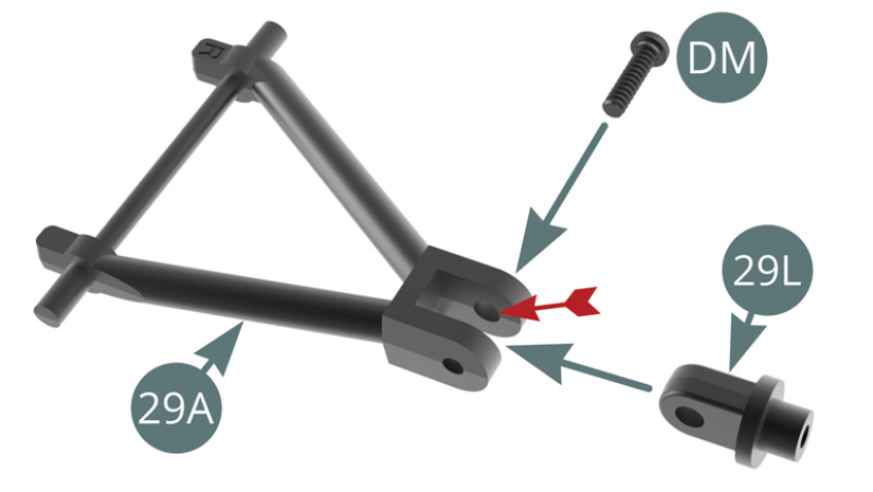
STEP 1
Position 29L hub carrier joint on 29A front upper wishbone and fix with a DM screw through the widest hole (red arrow), maintain mobility.
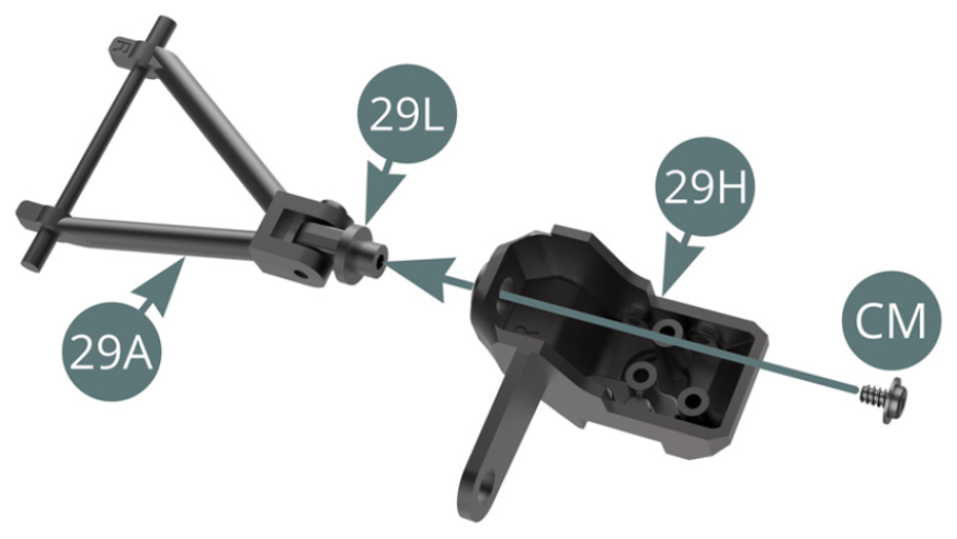
Position the top of 29H hub carrier on 29L hub carrier joint and fix with a CM screw, do not overtighten, allow the wheel to turn.
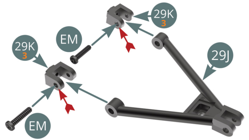
STEP 2
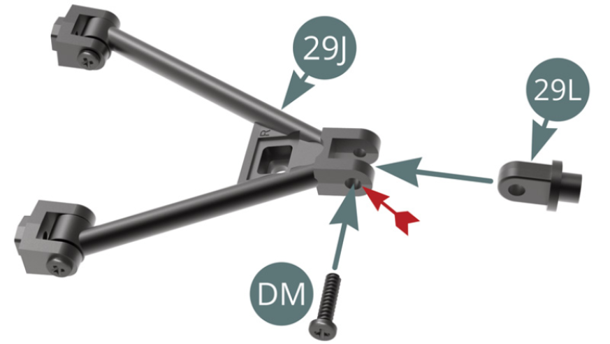
Position the two 29K lower wishbone supports (marked 3) successively on 29J lower front wishbone and secure each of them with an EM screw through the widest hole (red arrow), maintain mobility.
Position 29L hub carrier joint on 29J front lower wishbone and fix it with a DM screw through the widest hole (red arrow), maintain mobility.
STEP 3
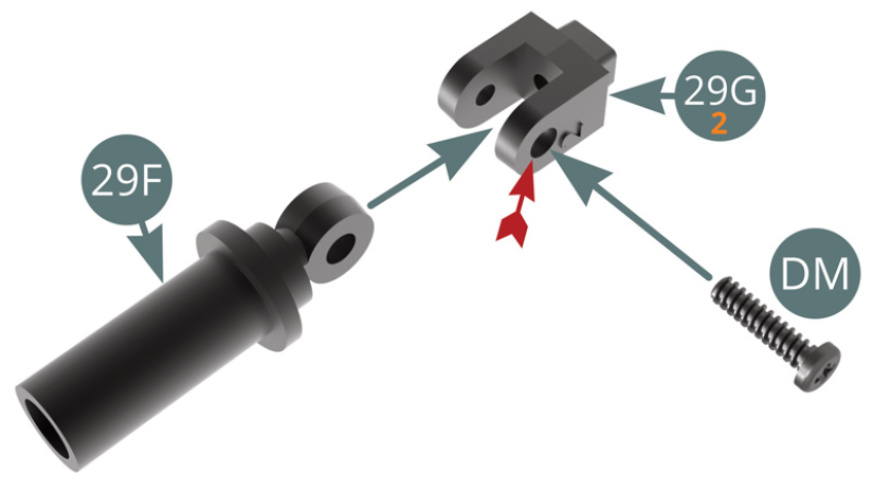
Position 29G Lower shock absorber support (marked 2) on 29F Shock cylinder and fix with a DM screw through the widest hole (red arrow), maintain mobility.
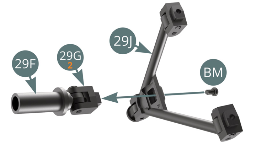
Position 29G Lower shock absorber support (marked 2) on 29J Front lower wishbone and fix with a BM screw.
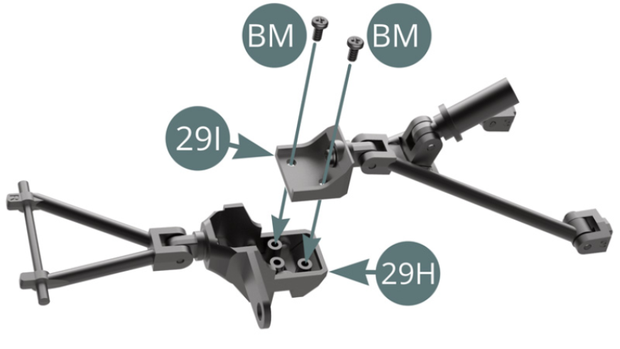
STEP 4
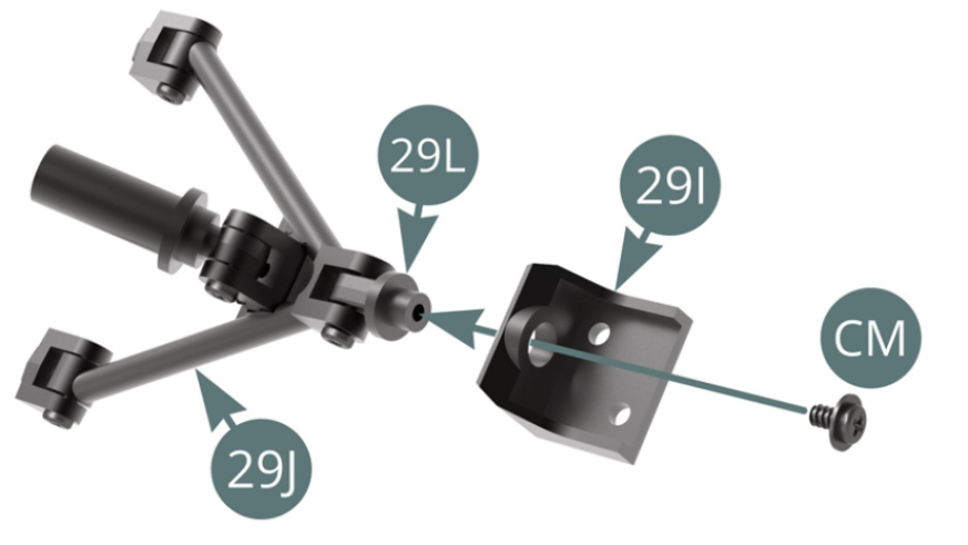
Position the bottom of 29I hub carrier on 29L hub carrier joint and secure with a CM screw, do not overtighten – allow the wheel to turn.
Position the bottom of 29I hub carrier on the top of 29H hub carrier and secure with two BM screws.
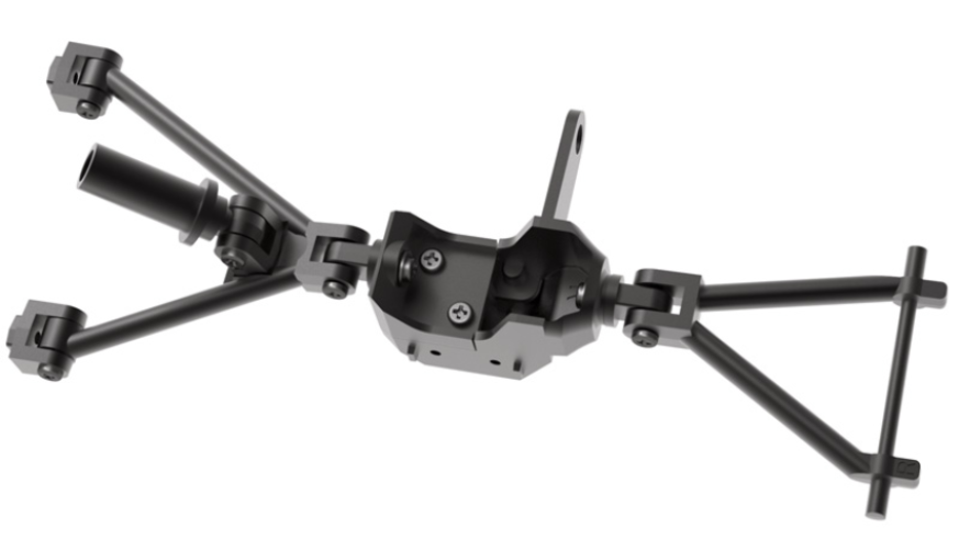
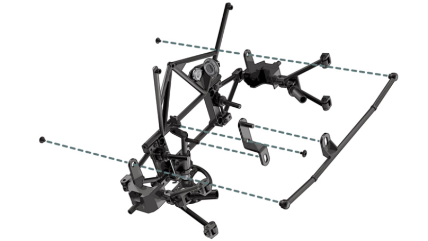
Pre-assembly of the right front suspension in unfolded position
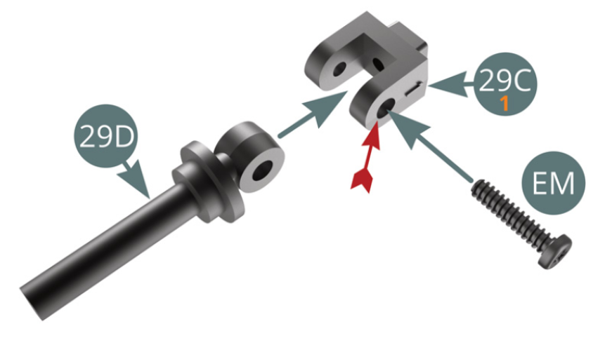
STEP 5
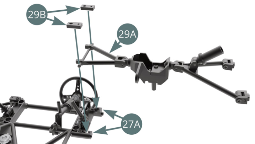
Position 29C upper shock absorber 29C (marked 1) on 29D shock piston and secure with an EM screw through the widest hole (red arrow), maintain mobility!
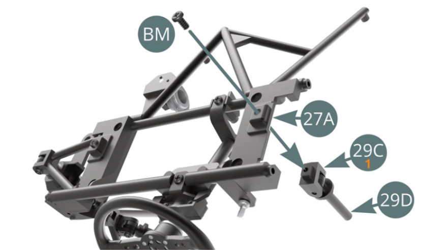
STEP 6
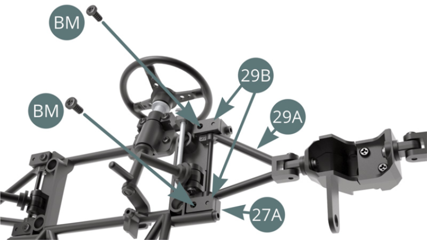
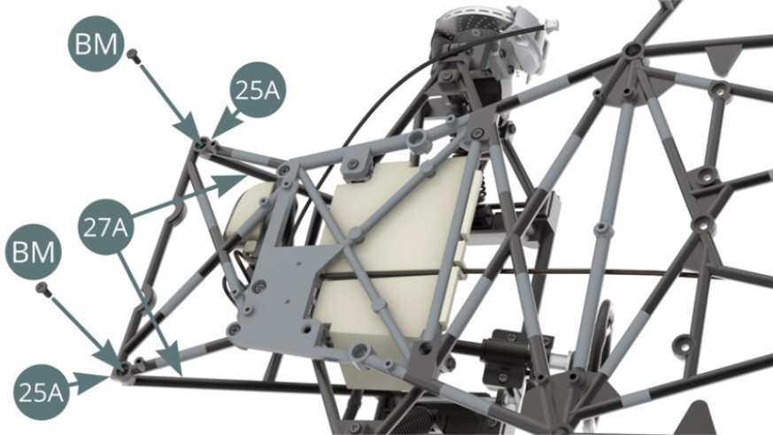
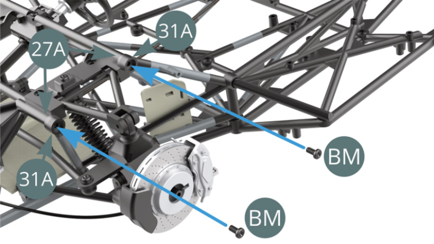
Position 29C upper shock absorber bracket (marked 1) on 27A dashboard frame and secure with a BM screw.
STEP 7
Position 29A upper front wishbone on 27A dashboard frame and secure with 29B brackets and two BM screws (shown above and opposite). Do not overtighten to allow movement.
ASSEMBLY DIAGRAM
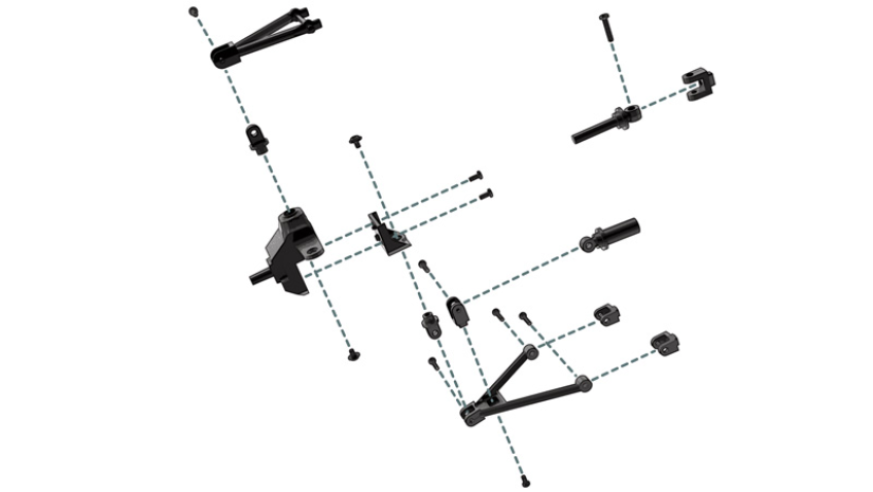
GENERAL VIEW
Kit 30
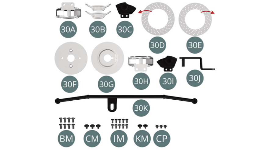
Parts of kit
- 30A Left brake caliper
- 30B Brake piston cover (x 2)
- 30C Left brake bailer / Brake force regulator
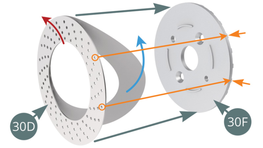
- 30D Inner surface of right brake disc (note direction of ventilation holes)
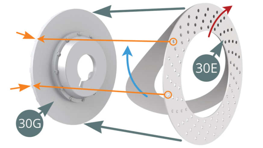
- 30E Outer surface of right brake disc (note direction of ventilation holes)
- 30F Right inner brake half disc
- 30G Right Outer Brake Half Disc
- 30H Right brake caliper
- 30I Right brake scoop
- 30J Steering Rod
- 30K Steering Bar
- BM Screw M 2.0 x 4 mm (x 8)
- CM Screw M 2.0 x 3 x 5 mm (x 3)
- IM Screw M 1.7 x 3.5 mm (x 10)
- KM Screw M 1.7 x 3 x 5 mm (x 2)
- CP Screw M 1.7 x 3 x 5 mm (x 3)
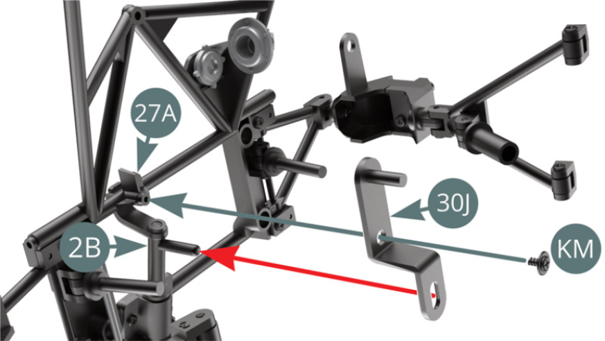
STEP 1
Position 30J steering link on 27A dashboard frame while engaging the lever at the end of the steering column in the slot provided (red arrow), then secure with a KM screw.
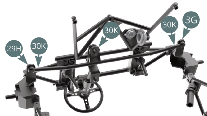
Position 30K steering bar on the upper hub carrier arms 29H and 3G, engaging it in the axis of the steering rod (red arrow) and secure with two CM screws.
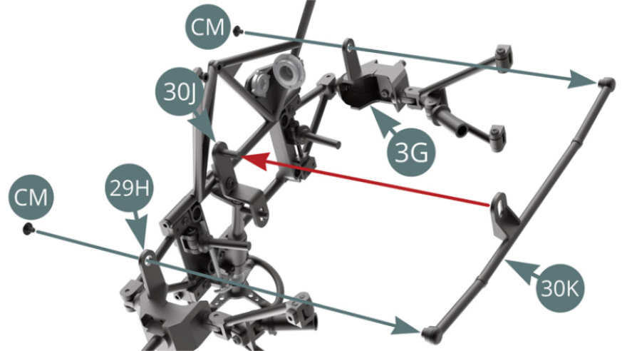
30K steering bar installed
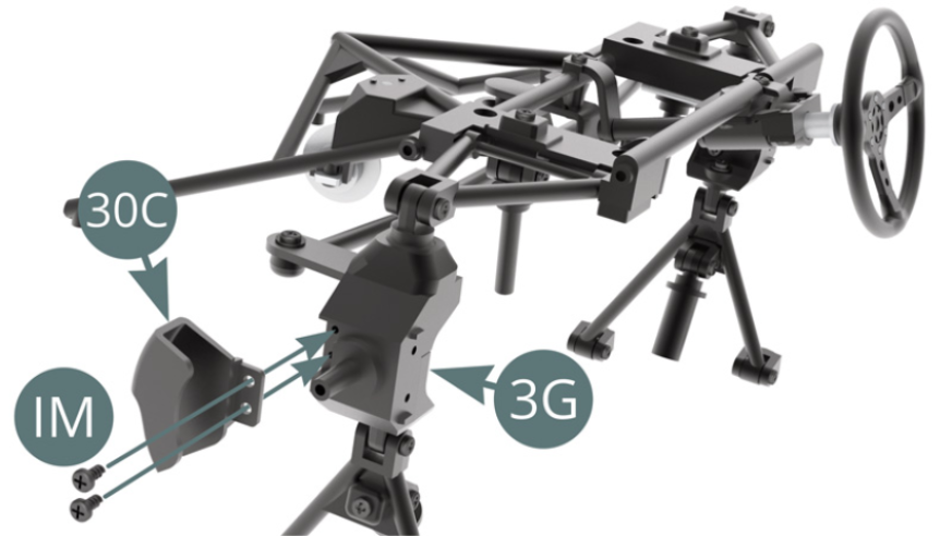
STEP 2
Position 30C left brake caliper on top of 3G hub carrier and secure with two IM screws.
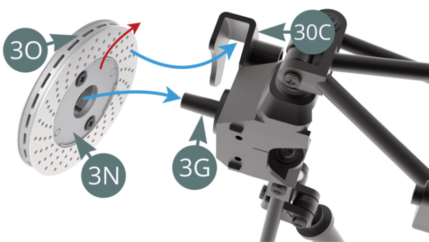
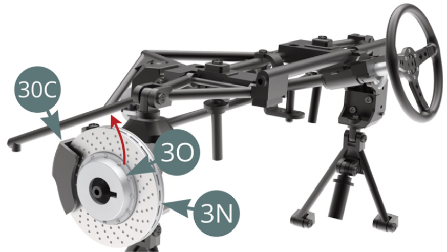
STEP 3
Position left brake disc 30-3N (note the direction of the ventilation holes, red arrow) on 3G hub carrier while inserting it into 30C Left brake bailer (blue arrows). Illustrations opposite.
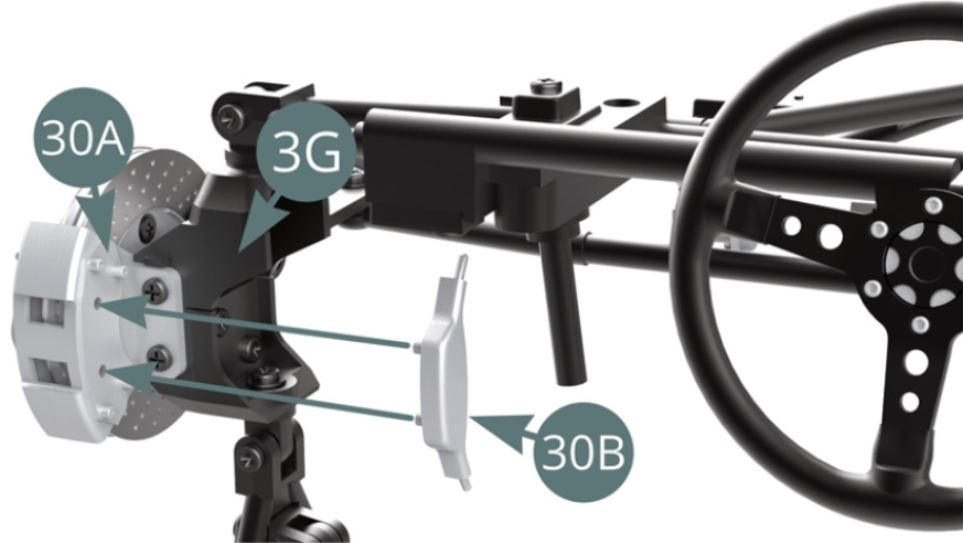
STEP 4
Position 30A left brake caliper on 3G hub carrier and secure with two IM screws.
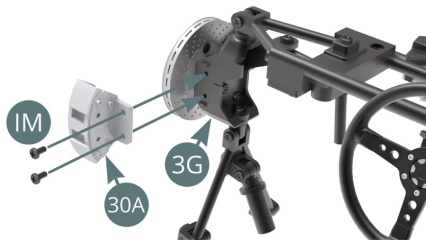
Position 30B piston cover on 30A left brake caliper.
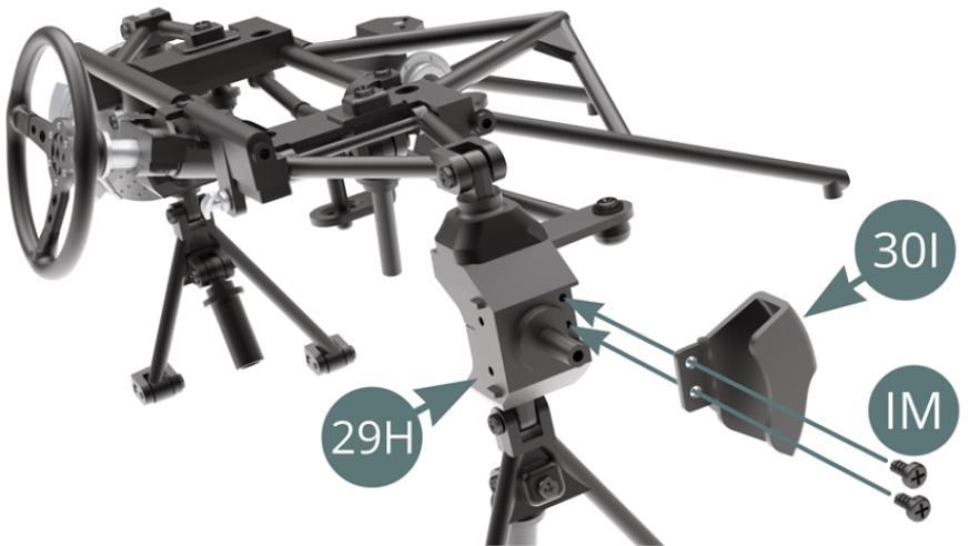
STEP 5
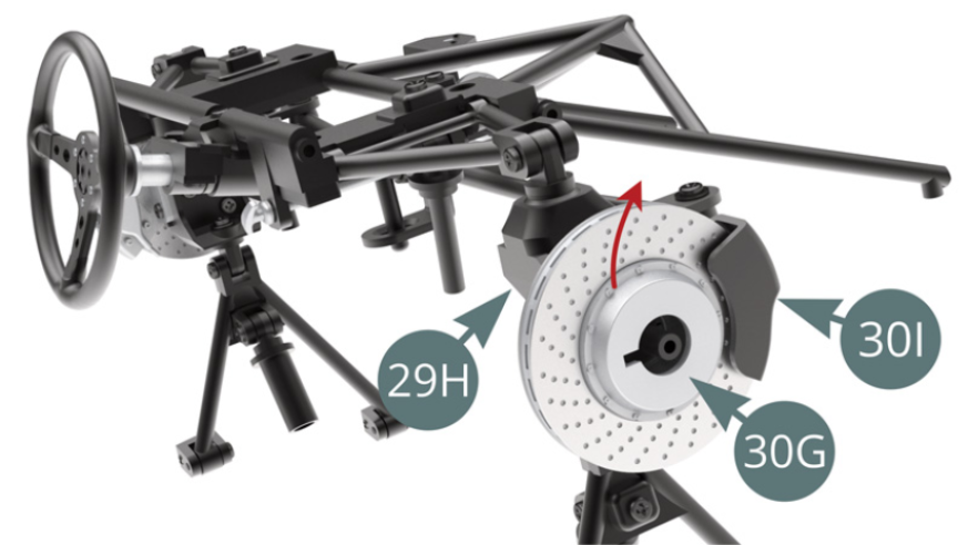
Position 30I right brake scoop on 29H hub carrier and secure with two IM screws.
Remove the backing paper (blue arrow) from the outer surface of 30E right brake disc and apply the adhesive to 30G right outer half brake disc (note the direction of the ventilation holes, red arrow). Ensure that the outer holes face the ribs of the disc (orange arrows).
STEP 6
Remove the backing paper (blue arrow) from the inner surface of 30D right brake disc and apply the adhesive to 30F right outer brake half disc (note the direction of the ventilation holes, red arrow). Ensure that the outer holes face the disc ribs (orange arrows).
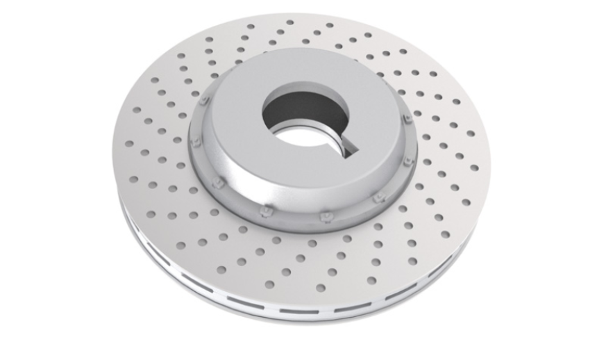
Put 30G and 30F outer half brake discs together and fix them with two CP screws.

Assembled right brake disc
STEP 7
Position the right brake discs 30G-30F (check the direction of the ventilation holes, red arrow) on 29H hub carrier while engaging it in the 30I right brake scoop (blue arrows). Illustrations opposite.
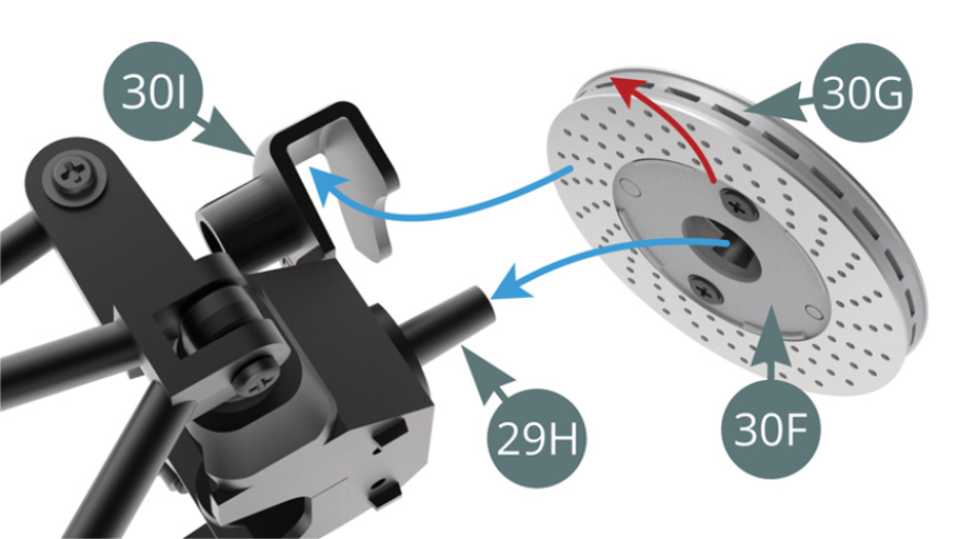
Right brake disc installed on 29H hub carrier
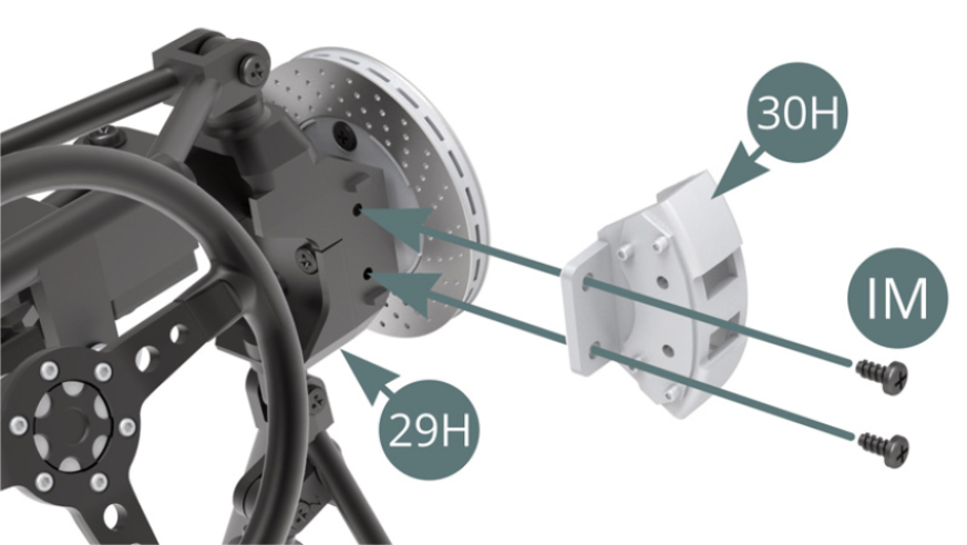
STEP 8
Position 30H right brake caliper on 29H hub carrier and secure with two IM screws.
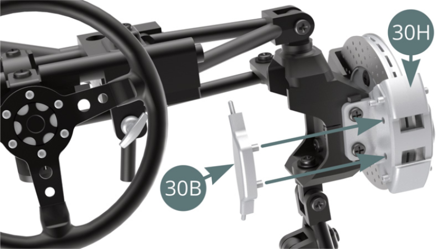
STEP 9
Position 30B piston cover on 30H right brake caliper.
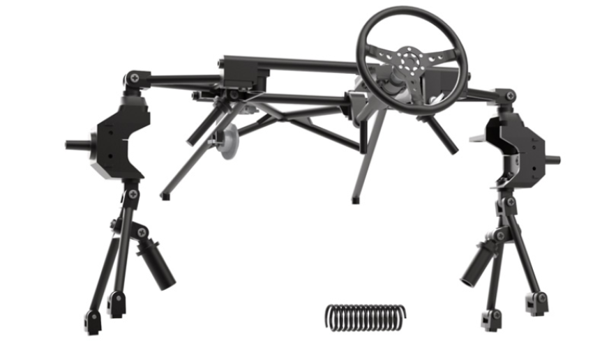
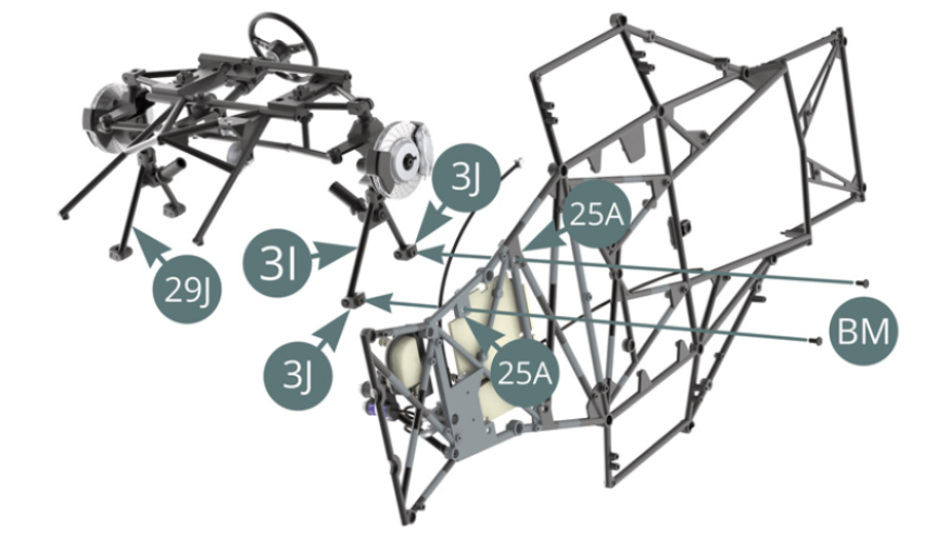
Pre-assembly of front suspension and steering
STEP 10
Install the front suspension by positioning the two lower swingarm brackets 3J /3I on 25A lower frame and fix them with two BM screws.
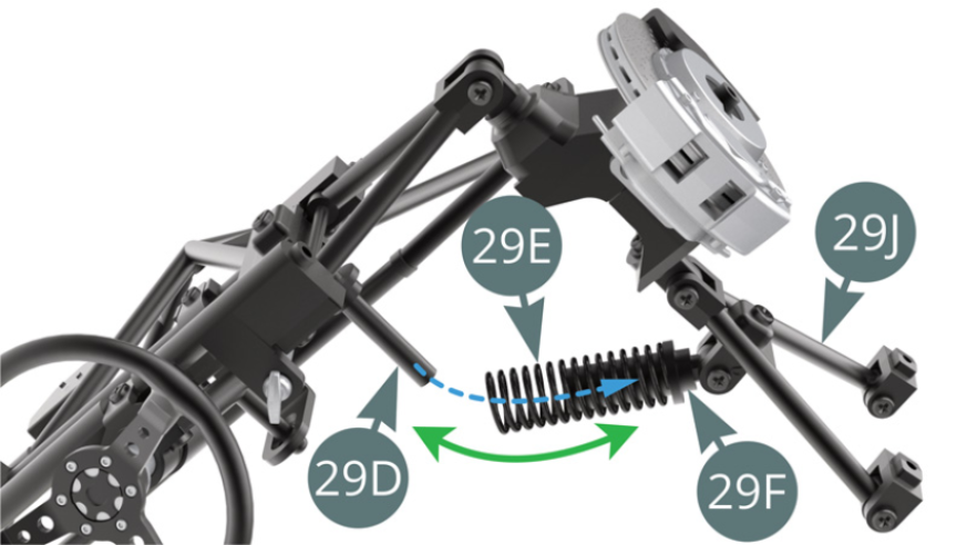
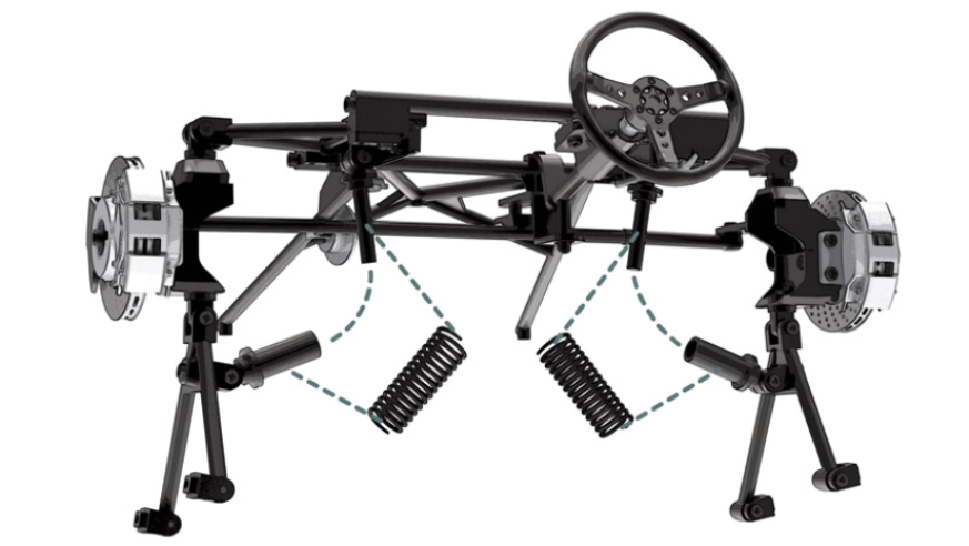
Position 29E shock absorber spring (interchangeable with 3D spring) on 29F shock absorber cylinder, then while tilting the assembly (green arrow), position 29D shock absorber piston in 29F shock absorber cylinder and through 29E spring (blue dotted arrow).
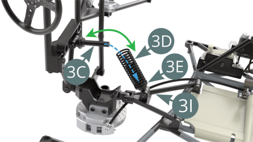
STEP 11
Position 3D shock spring (interchangeable with 29E spring) on 3E shock absorber cylinder, then while tilting the assembly (green arrow), position 3C shock absorber piston in 3E shock absorber cylinder and through 3D spring (blue dotted arrow).
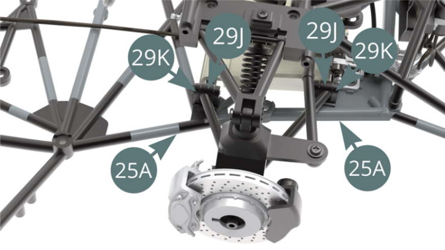
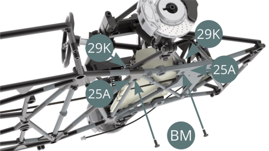
While tilting, align 27A dashboard frame arms (blue arrows) and 29K lower wishbone brackets (red arrows) in their respective housings on the lower frame 25A.
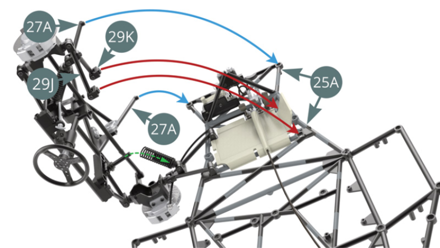
STEP 12
Attach the frame arms of 27A instrument panel to the ends of 25A lower frame with two BM screws.
Align the two 29K lower wishbone brackets with the slots on the upper right of the lower frame 25A.
STEP 13
Attach the two 29K lower wishbone brackets to 25A lower chassis with two BM screws.
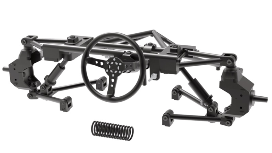
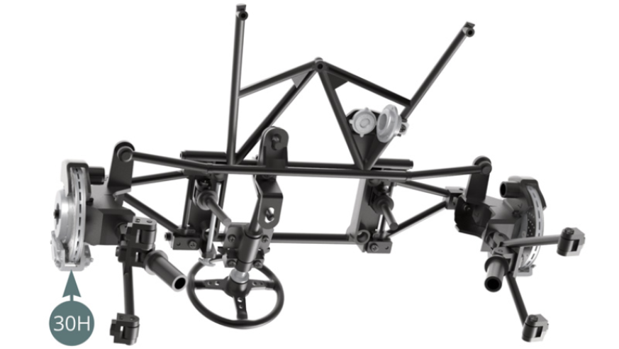
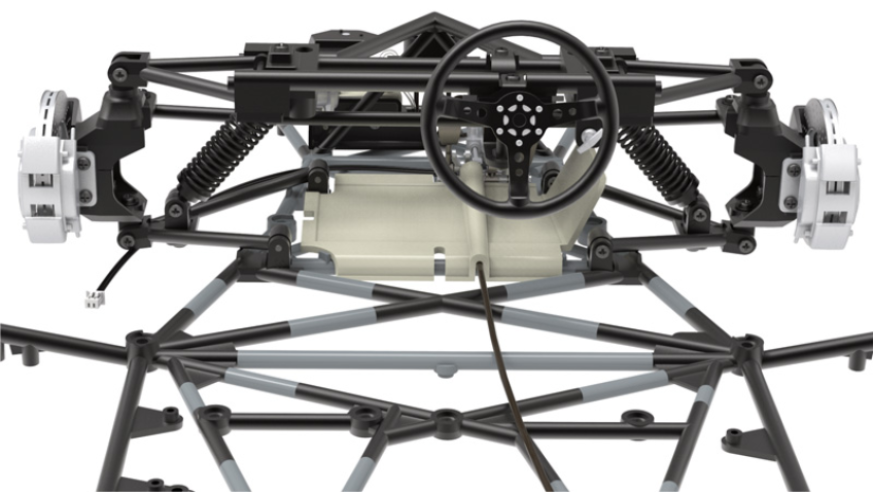
Front suspension and steering installed on the chassis
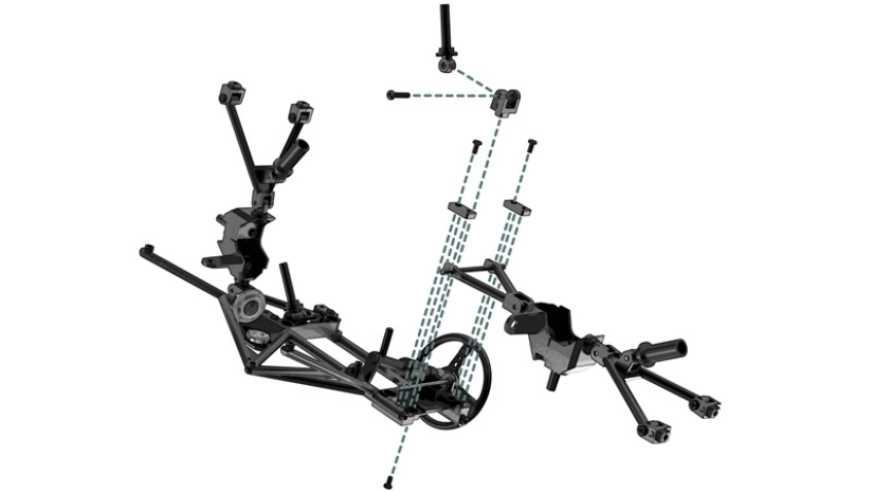
ASSEMBLY DIAGRAM
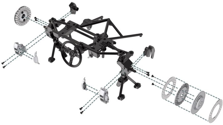
GENERAL VIEW

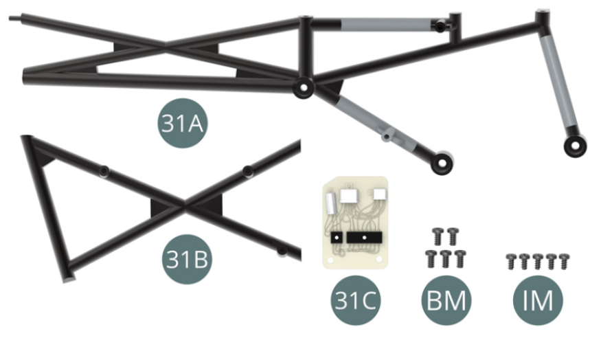
Kit 31
Parts of kit
- 31A Chassis
- 31B Chassis
- 31C Wiring board
- BM Screw M 2 x 4 mm (x 5)
- IM Screw M 1.7 x 3.5 mm (x 5)
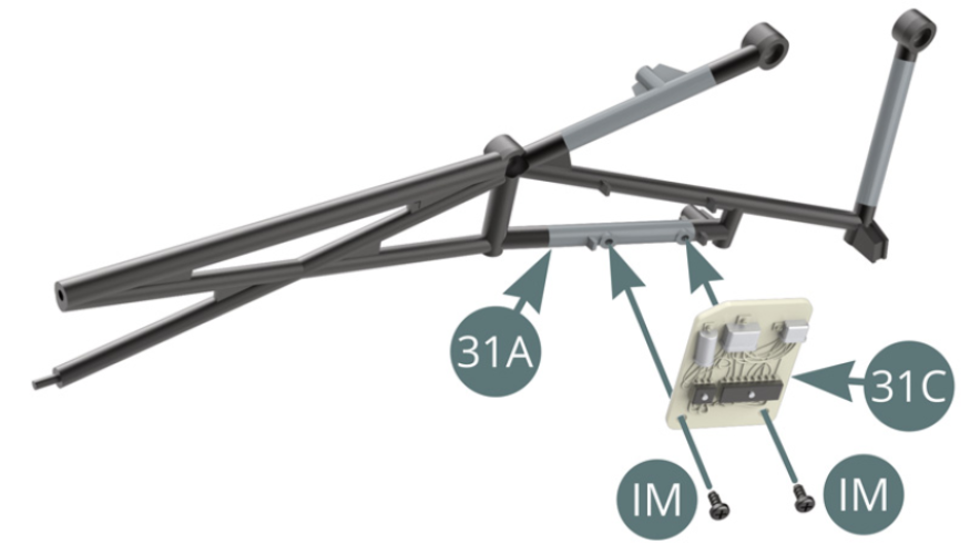
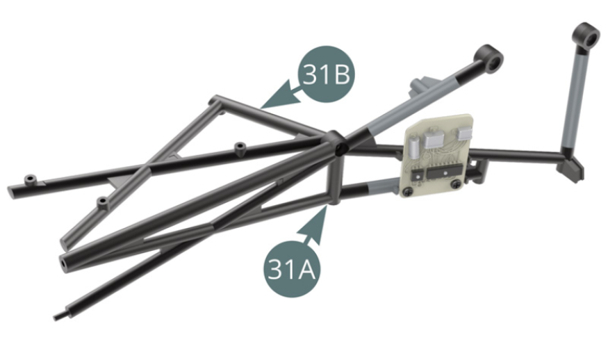
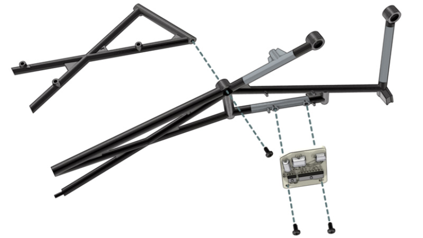
STEP 1
Position 31C wiring board on 31A chassis and secure it with two IM screws.
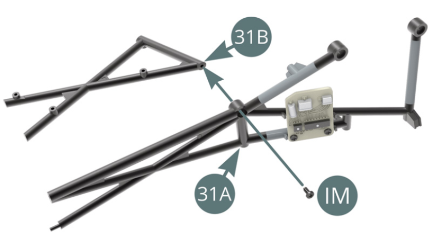
Position 31B chassis on 31A chassis and fix it with an IM screw.
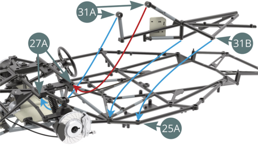
STEP 2
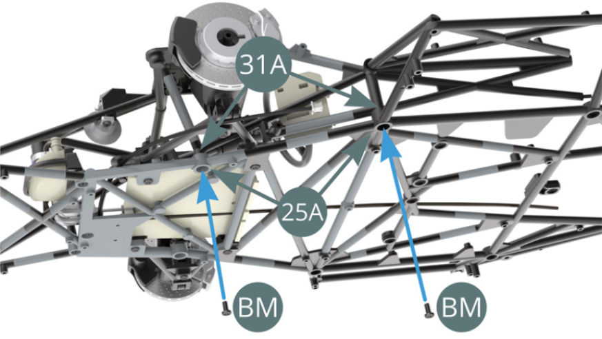
Install 31A-31B pre-assembly (illustration opposite) on 25A lower chassis and 27A dashboard frame (red arrow and blue arrows – see right hand illustration). Please check carefully the illustrations in the next step for a good understanding of the attachment points.
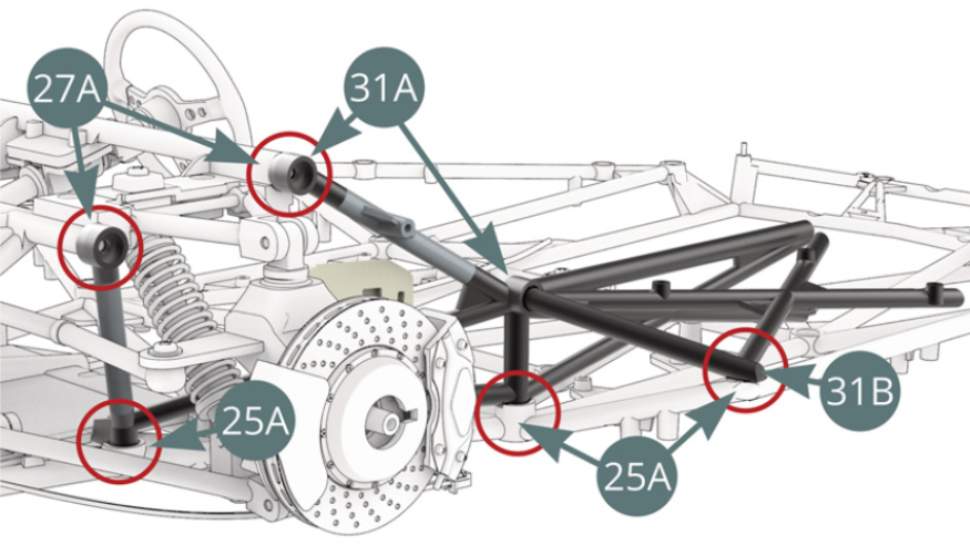
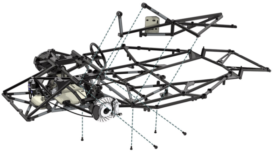
STEP 3
Locate the five attachment points (red circles) between 31A-31B chassis and 25A lower chassis assembly / 27A dashboard frame will be fixed with their respective screws as shown in the following two steps.
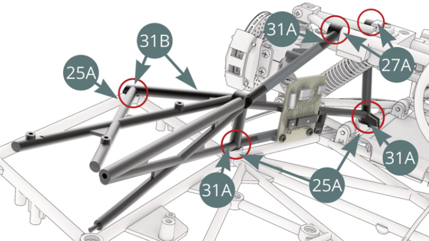
STEP 4
Secure 31A chassis to the 27A dashboard frame with two BM screws.
Attach 31A chassis to 25A bottom chassis with two BM screws.
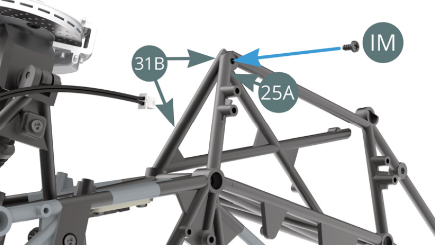
STEP 5
Secure the 31B chassis to the 25A lower chassis with an IM screw.
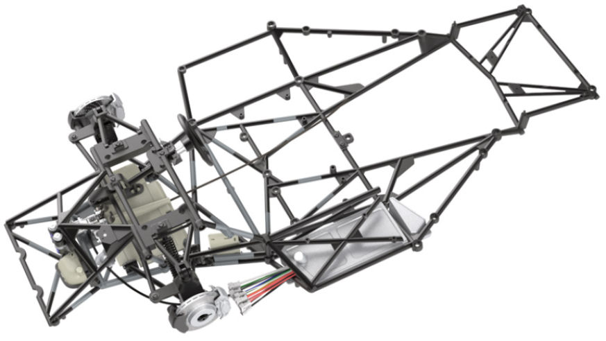
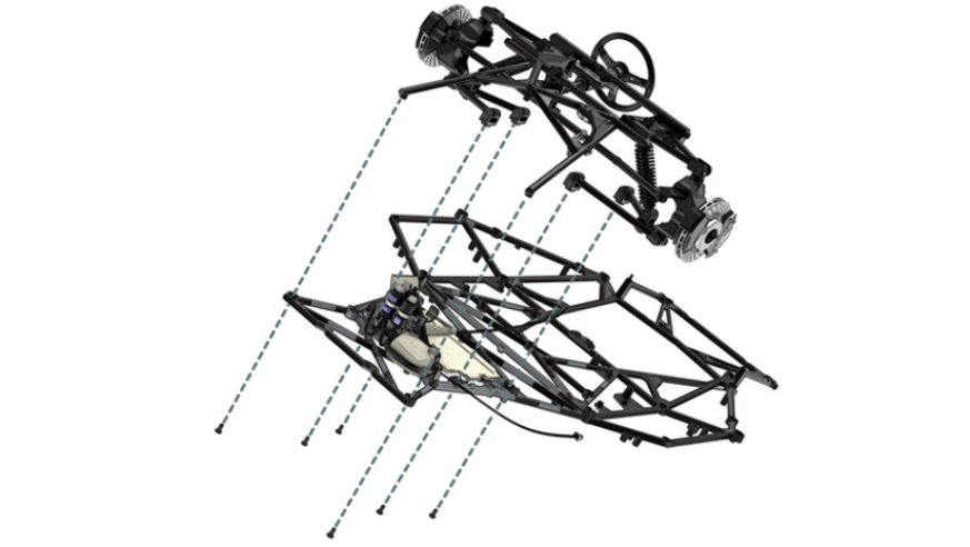
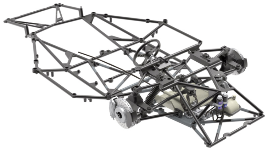
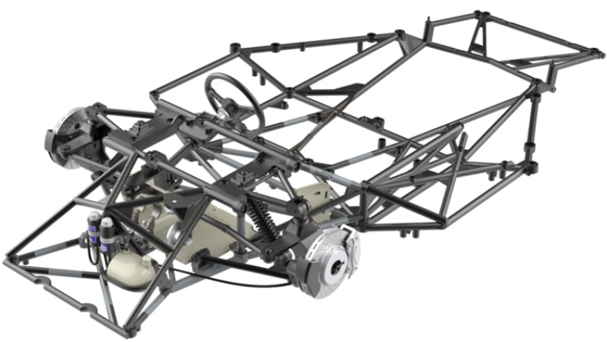
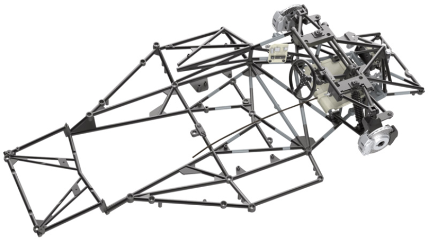
View of the tubular mesh assembly frame at cockpit level
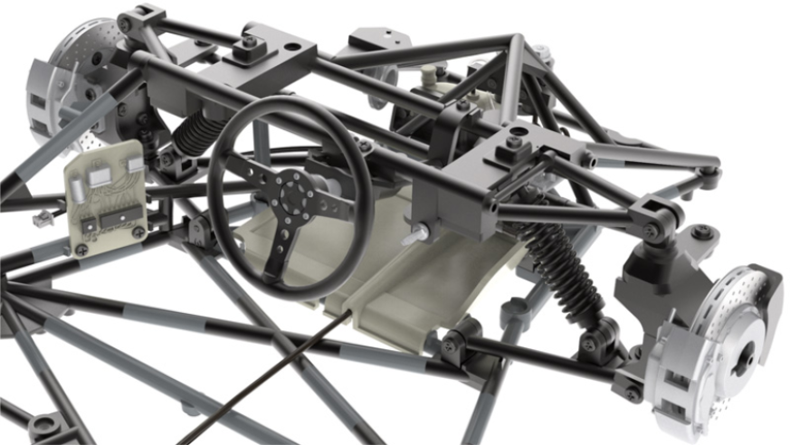
ASSEMBLY DIAGRAM
GENERAL VIEW
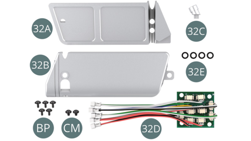
Kit 32
Parts of kit
- 32A Top panel
- 32B Left fuel tank
- 32C Filling pipe/neck
- 32D Printed circuit board with wires
- 32E Spacer washers
- BP Screw M 1.7 x 4 x 5 mm (x 5)
- CM Screw M 2.0 x 3 x 5 mm (x 2)
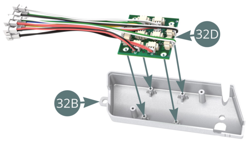
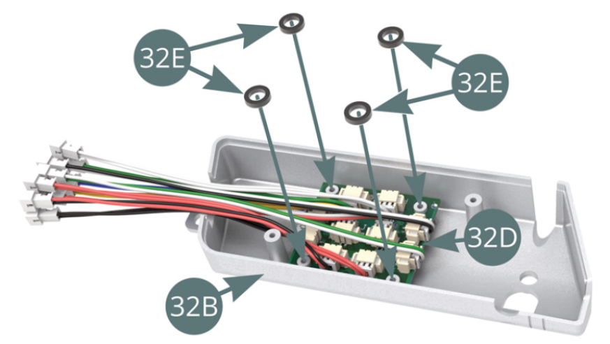
STEP 1
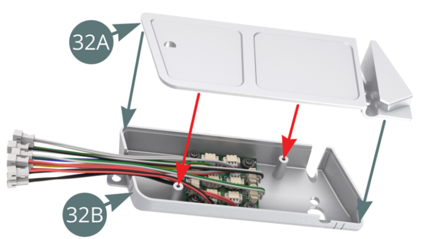
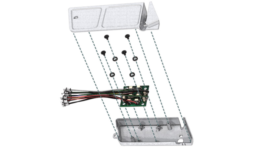
Position the 32D printed circuit board on the four pins located inside the 32B fuel tank, then place a washer above each of them (illustrations opposite).
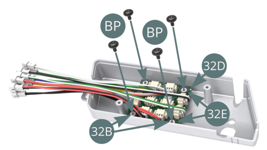
STEP 2
Attach the 32D PCB to the 32B fuel tank with four BP screws.
Position 32A top panel on 32B fuel tank using the two pins (red arrows).
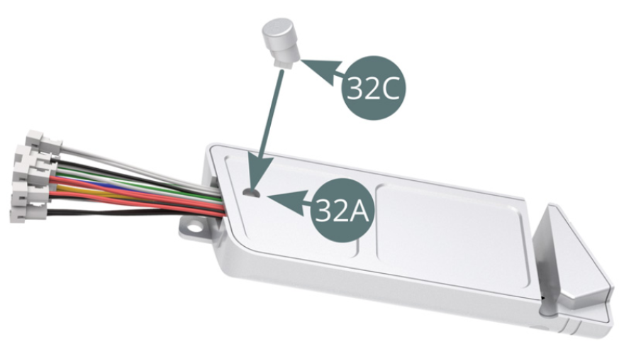
STEP 3
Position the 32C filling neck on the top panel of 32A left fuel tank.
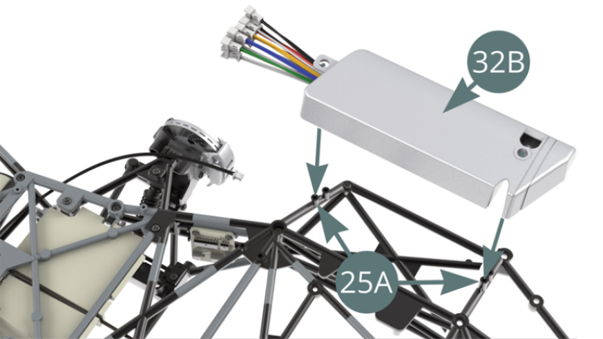
STEP 4
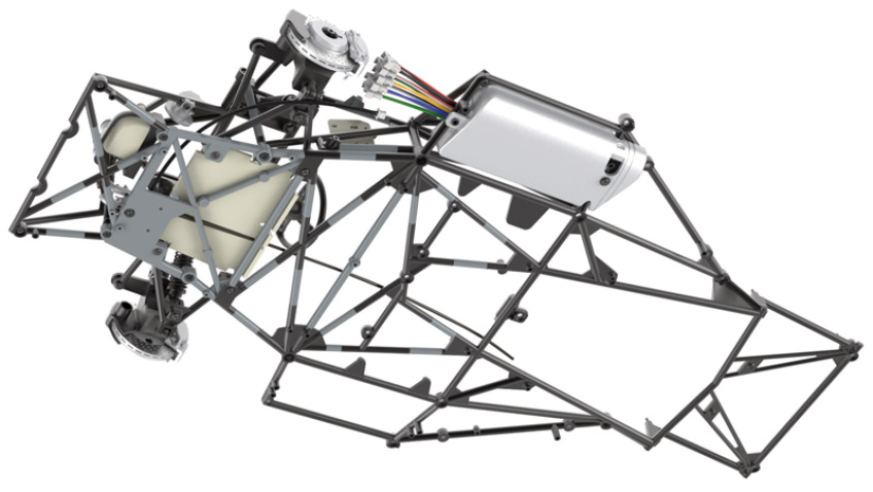
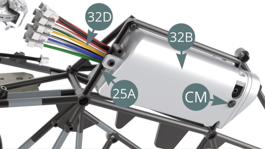
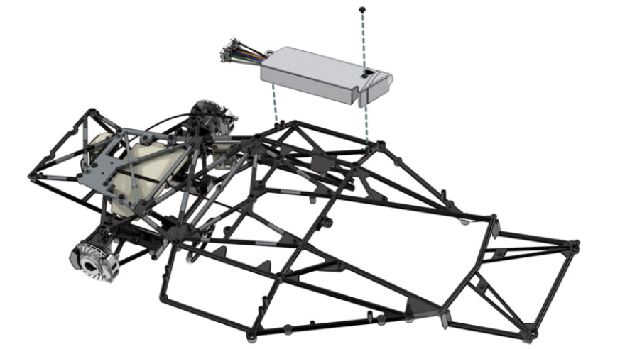
Position 32B fuel tank on the lugs provided on 25A lower chassis and secure with a CM screw (illustrations opposite). Refer to the illustrations in the next step for the arrangement of the cables.
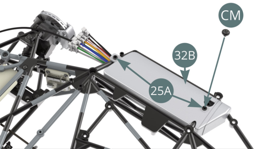
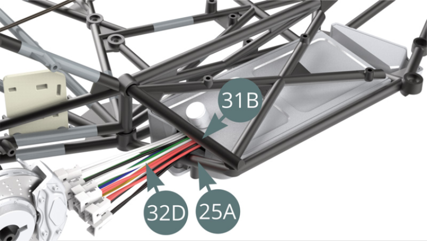
STEP 5
32D electrical wires must run between 25A lower chassis and 31B chassis as shown in the illustrations below.
ASSEMBLY DIAGRAM
GENERAL VIEW