English
 français
 Deutsch
 español
 italiano
 português


Box 1
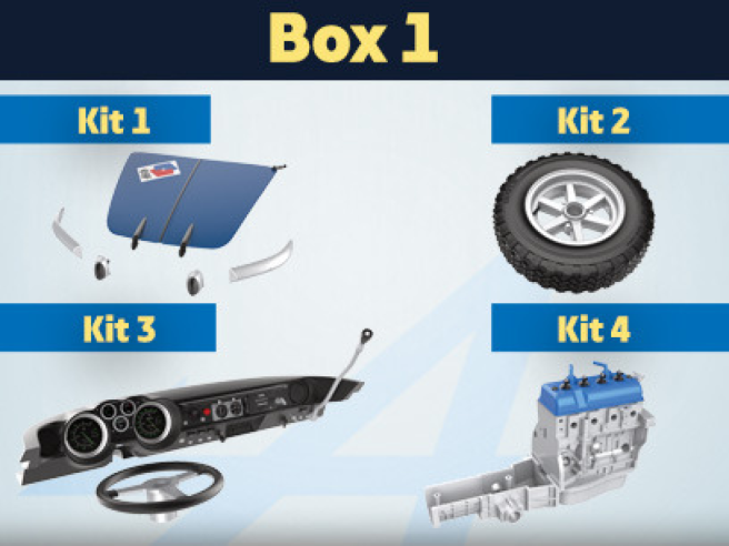
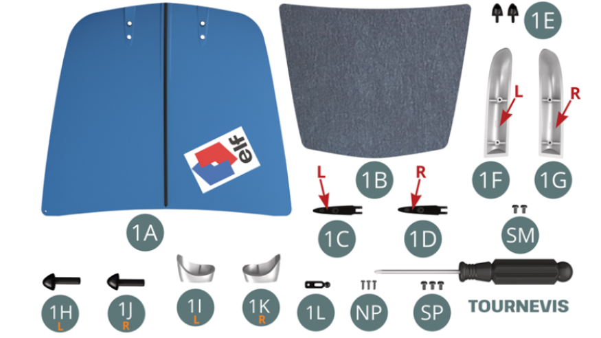
Kit 1 - Assembly of the bonnet and front bumpers
Parts of kit
- 1A Bonnet
- 1B Bonnet insulation panel
- 1C Left-hand bonnet hinge (marked L)
- 1D Right hand bonnet hinge (marked R)
- 1E Hinge bracket (x 2)
- 1F Left front bumper (marked L)
- 1G Right front bumper (marked R)
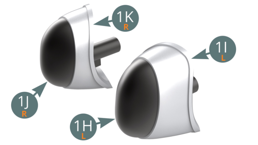
- 1H Left bumper rubber
- 1I Left bumper stop
- 1J Right bumper rubber
- 1K Right bumper stop
- 1L Bonnet lock
- Screwdriver
- Screw NP M 1,2 x 4 mm (x 3)
- Screw SP M 1,7 x 3 mm (x 3)
- Screw SM M 1,7 x 3 mm (x 2)
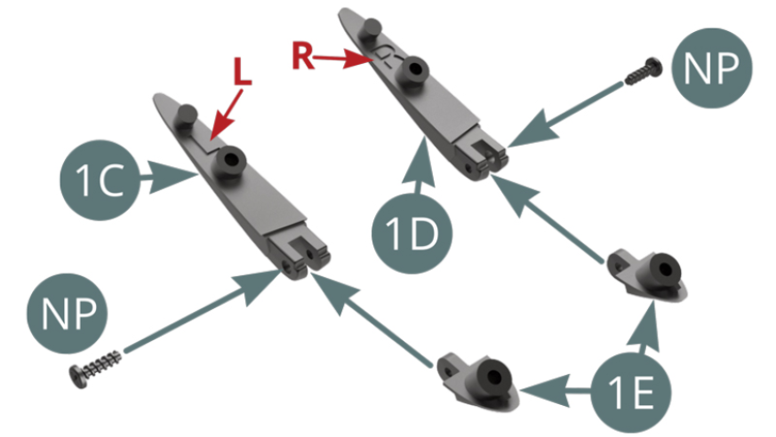
Step 1
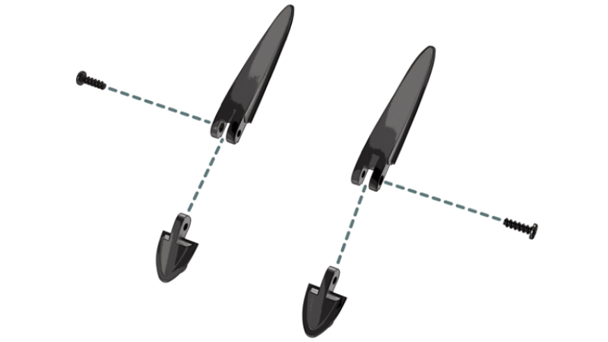
Place the left (1C) and right (1D) bonnet hinges on bracket ( 1E) and secure each with an NP screw.
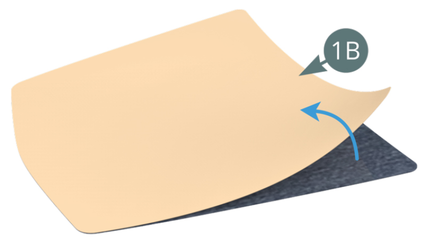
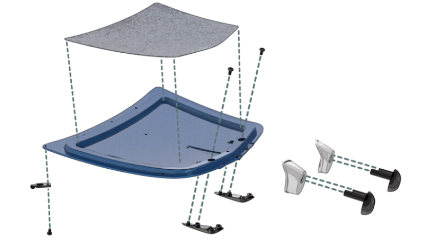
Remove the bonnet insulation panel (1B) from the paper support.
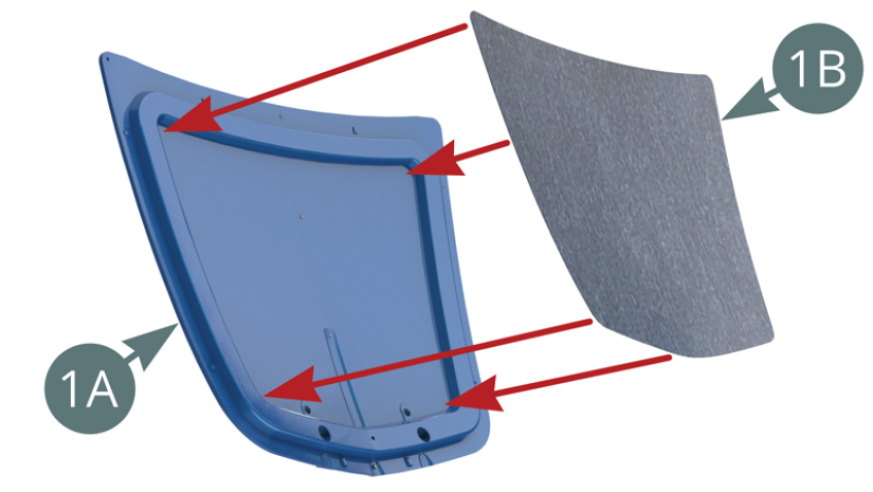
Step 2
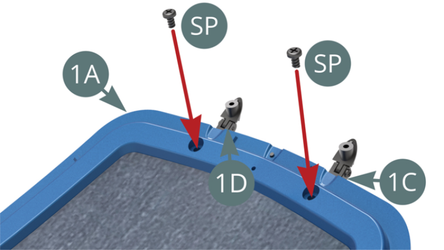
Apply and smooth the insulation panel (1B) to the inner face of the bonnet (1A). Position the left (1C) and right (1D) bonnet hinges on the bonnet (1A) and secure with two SP screws as shown in the illustration above.
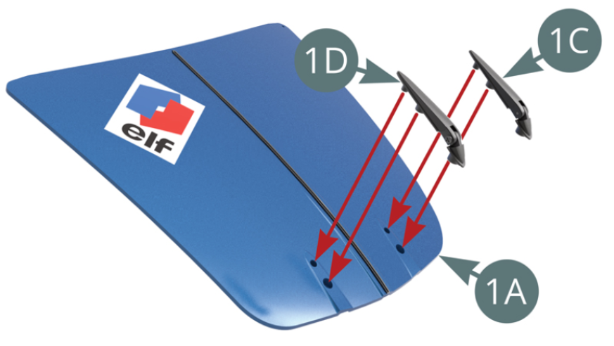
Step 3
Left (1C) and right (1D) bonnet hinges attached to the bonnet (1A) with two SP screws - shown opposite and below,
Step 4
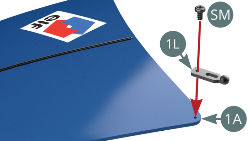
Position the bonnet lock (1L) on the bonnet (1A) and secure with a SM screw - shown above.
Step 5
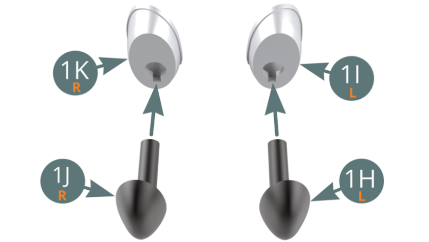
Position the rubbers (1H and 1J) respectively on the left (1I) and right (1K) bumper stops - shown above.
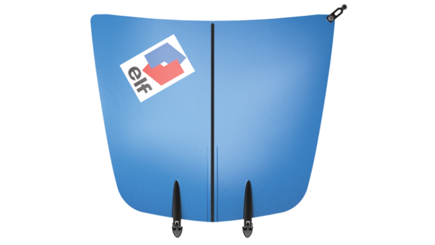
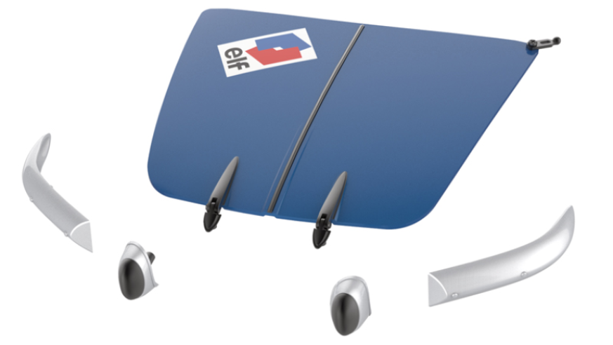
ASSEMBLY DIAGRAM

GENERAL VIEW
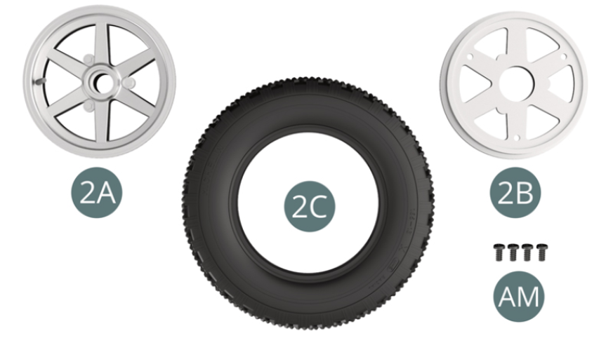
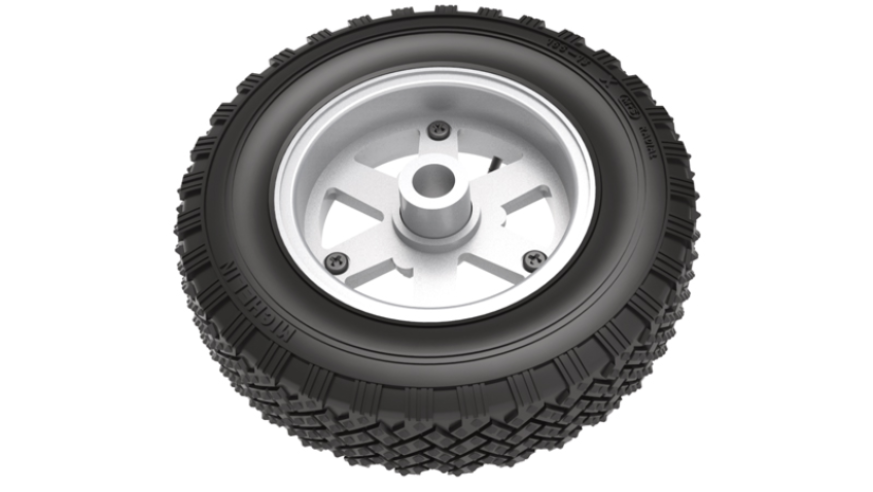
Kit 2 - Assembly of the left front wheel
Parts of kit
- 2A Outer wheel rim
- 2B Inner wheel rim
- 2C Tyre
- Screw CM M 2,0 x 4 mm (x 4)
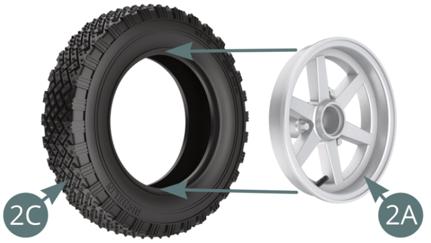
Step 1
Position the outer wheel rim (2A) into the tyre (2C).
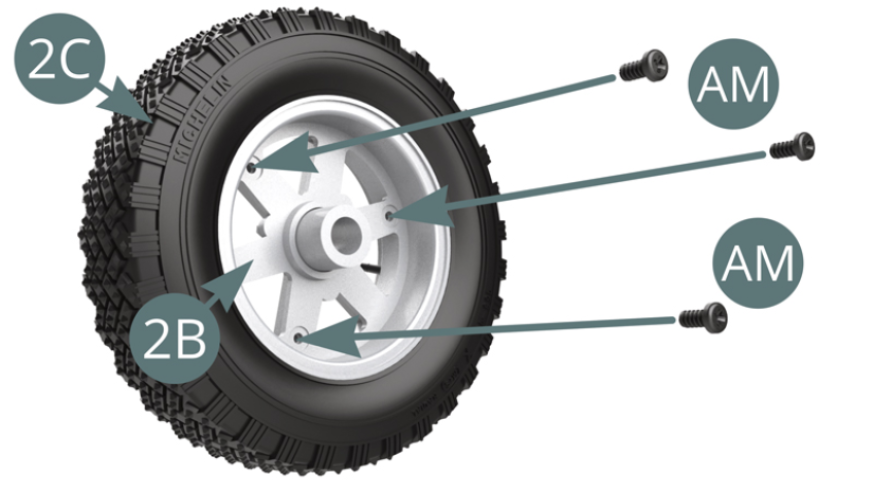
Step 2
Position the inner wheel rim (2B) into the tyre (2C), aligning it with the outer rim (2A) and secure it with three CM screws (shown above).

ASSEMBLY DIAGRAM
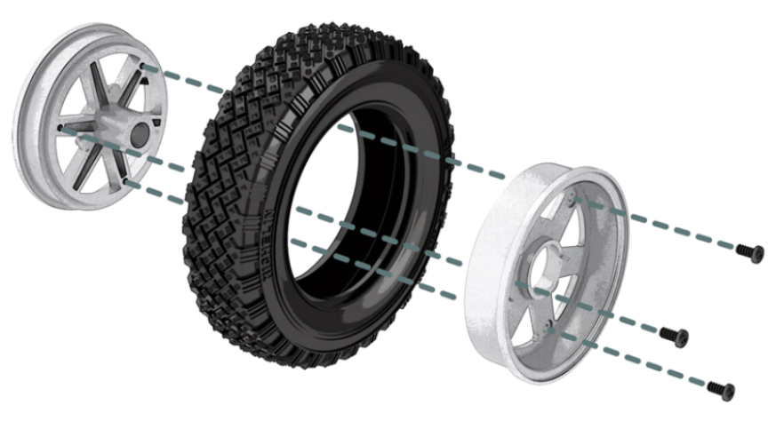
GENERAL VIEW

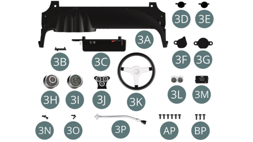
Kit 3 - Assembly of the dashboard
Parts of kit
- 3A Dashboard
- 3B Fan control
- 3C Display panel
- 3D Left fan flap
- 3E Right fan flap
- 3F Left fan flap bracket
- 3G Right fan flap bracket
- 3H Rev counter
- 3I Speedometer
- 3J Oil gauge and voltmeter block
- 3K Steering wheel
- 3L Timing block
- 3M Tripmaster
- 3N Switch
- 3O Switch
- 3P Reading lamp
- Screw AP M 1,7 x 4 mm (x 6)
- Screw BP M 1,7 x 5 mm (x 3)
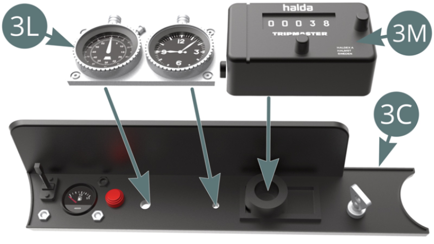
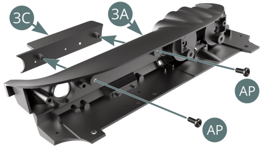
Step 1
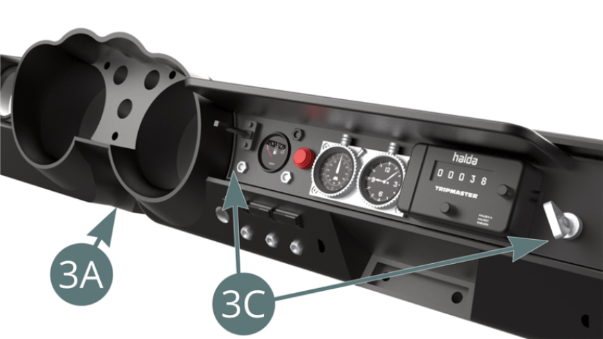
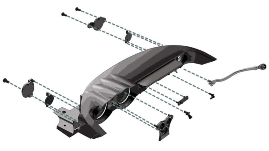
Position the timing block (3L) and the tripmaster (3M) on the display panel (3C). Position the display panel (3C) onto the dashboard (3A) and secure with two AP screws.
Step 2
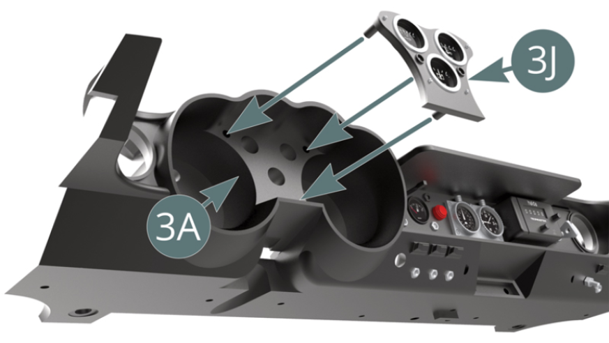
Display panel (3C) positioned on the dashboard (3A). Position the oil gauge and voltmeter block (3J) on the dashboard (3A).
Step 3
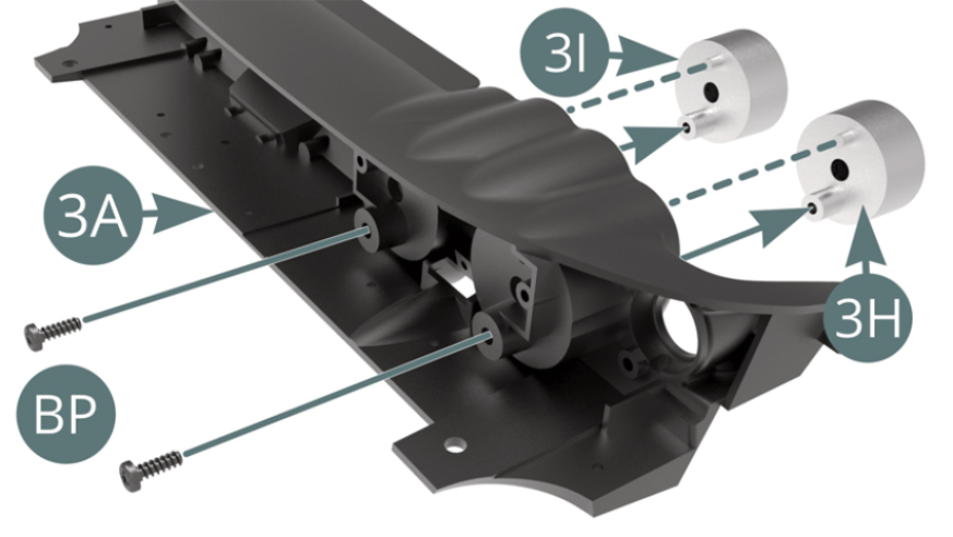
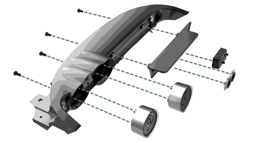
Position the rev counter (3H) and the speedometer (3I) on the dashboard (3A) and secure with two BP screws (see illustrations opposite and below). Position the fan control (3B) on the dashboard (3A).

Step 4
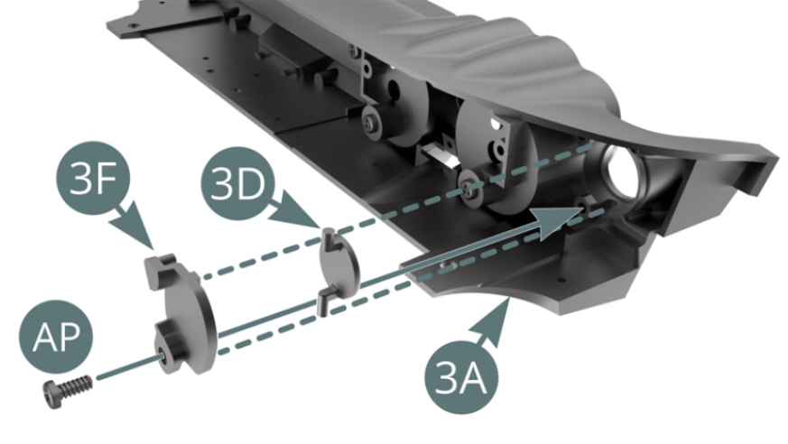
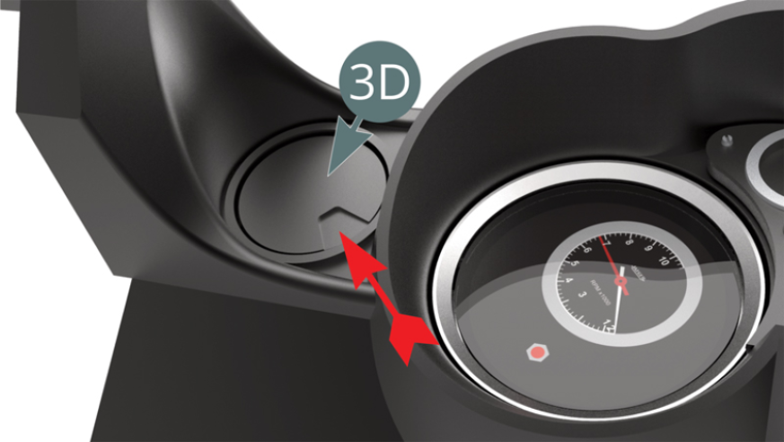
Position the left fan flap (3D) on the air outlet on the left side of the dashboard (3A) and keep it in place with the bracket (3F) fixed with an AP screw (illustrations above).
Step 5
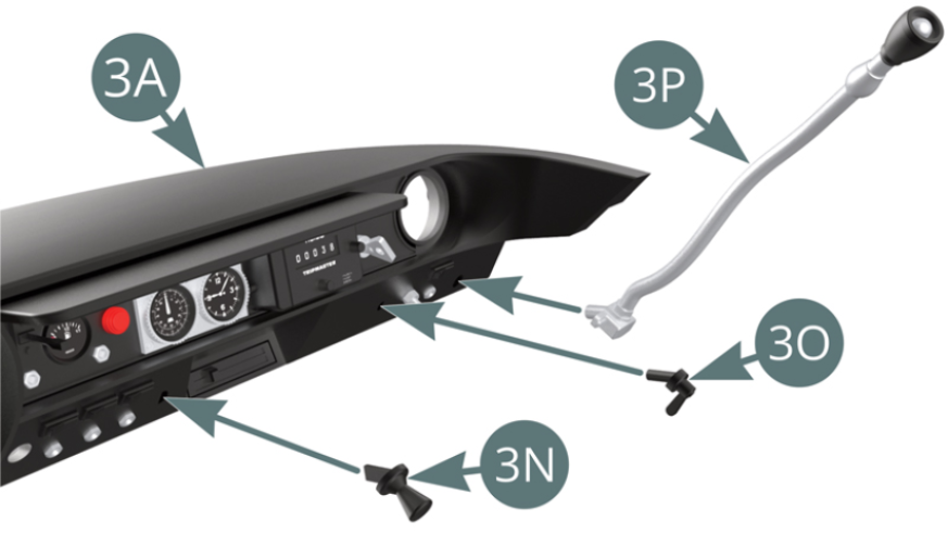
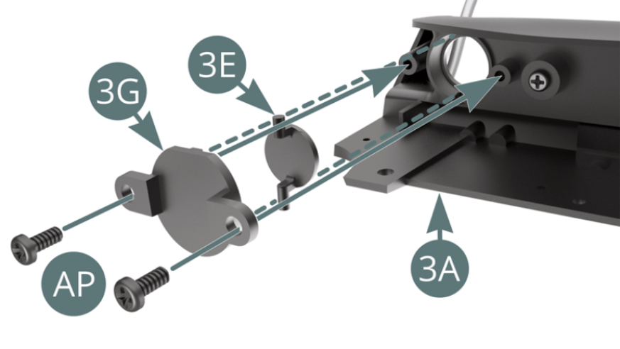
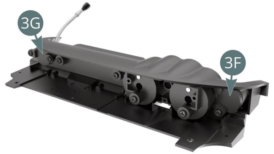
Position the two switches (3N and 3O) and the reading lamp (3P) on the dashboard (3A). Position the right fan flap (3E) on the air outlet on the right-hand side of the dashboard (3A) and fasten it with the bracket (3G) secured with two AP screws (see illustrations).
Step 6
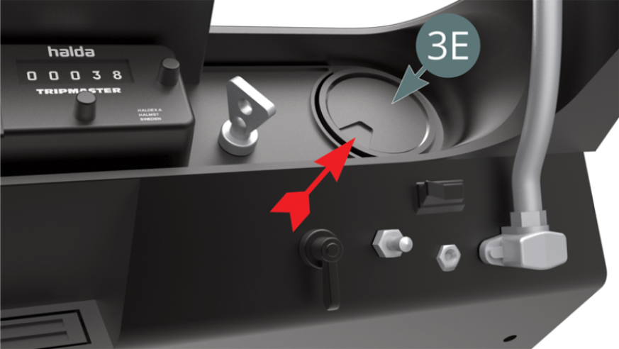
Check the correct orientation of the right fan flap (3E). Fan flaps (3F and 3G) positioned.
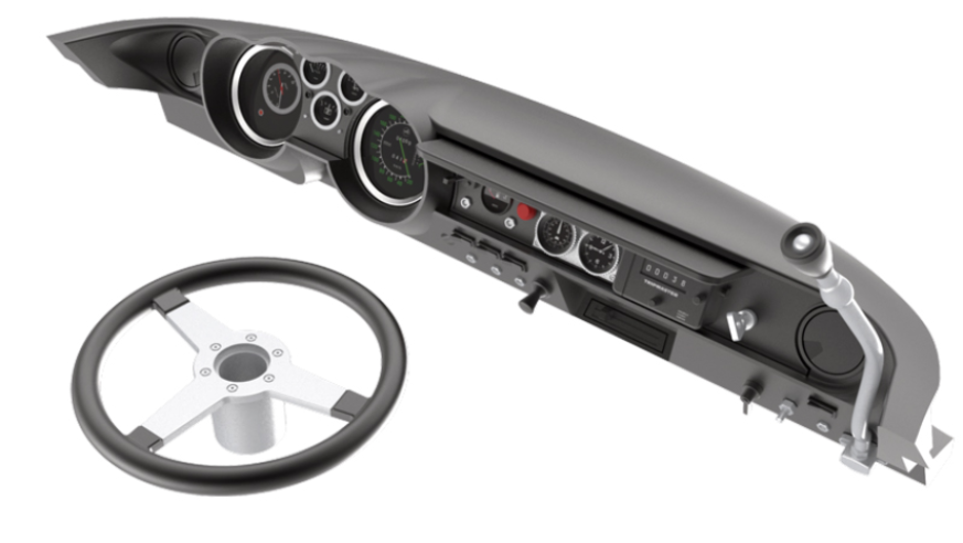
ASSEMBLY DIAGRAM
GENERAL VIEW

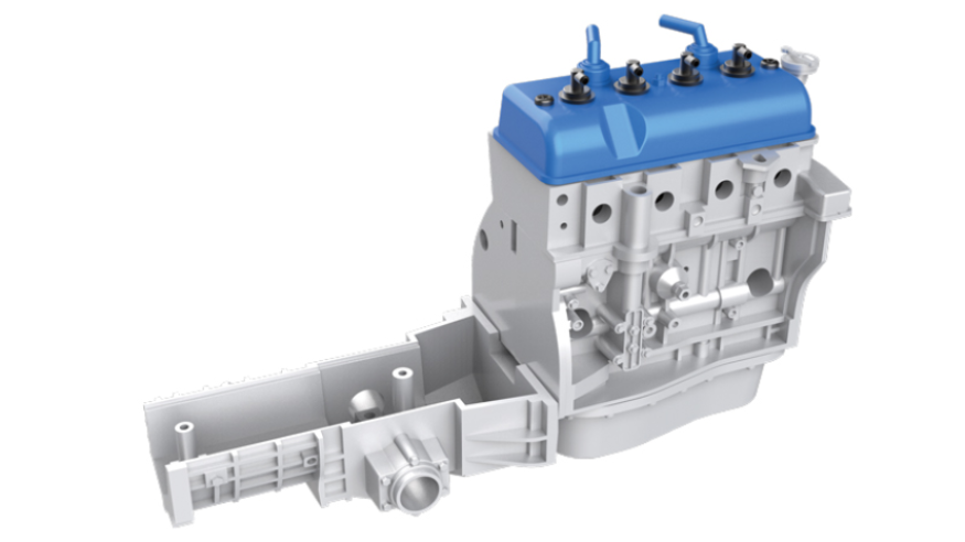
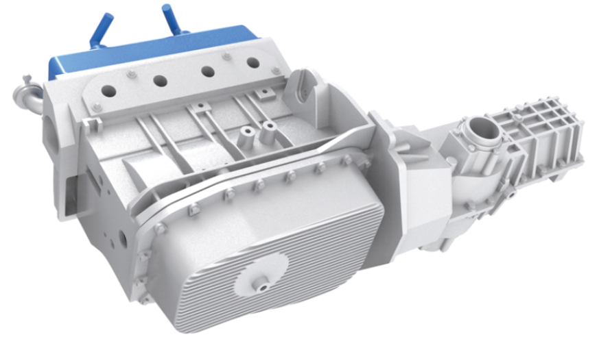
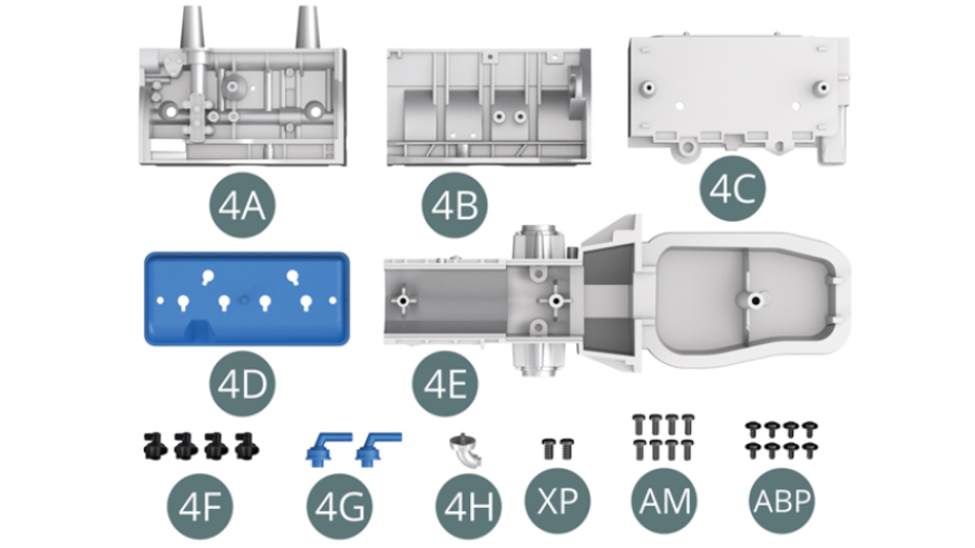
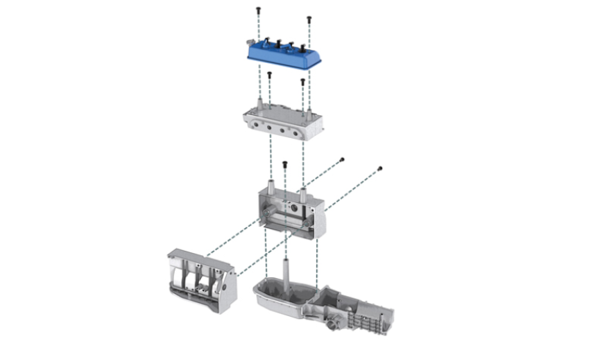
Kit 4 - Assembly of the engine block
Parts of kit
- 4A Left engine block
- 4B Right engine block
- 4C Top of engine block
- 4D Cylinder head
- 4E Oil pan and transmission
- 4F Spark plug (x 4)
- 4G Air inlet pipe (x 2)
- 4H Oil filler spout
- Screw XP M 2.3 x 4 mm (x 2)
- Screw AM M 1.7 x 3 mm (x 8)
- Screw ABP M 1.4 x 3 x 4 mm (x 8)
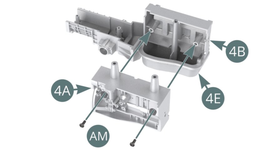
Step 1
Position the left (4A) and right (4B) engine blocks on the oil pan (4E) and fasten them together with two AM screws.
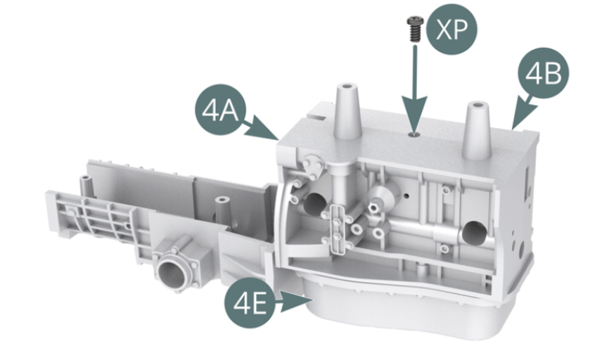
Secure the left (4A) and right (4B) engine blocks to the oil pan and transmission (4E) with an XP screw.
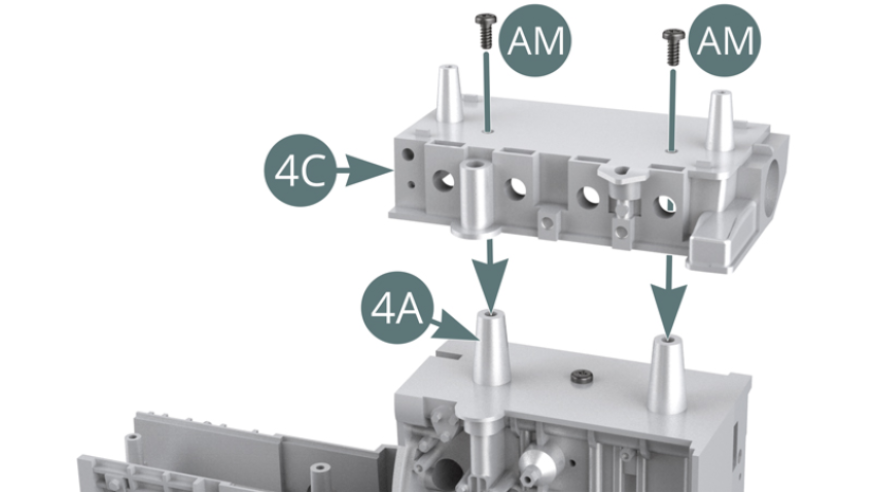
Step 2
Position the top of the engine block (4C) onto the left engine block (4A) and secure with two AM screws.
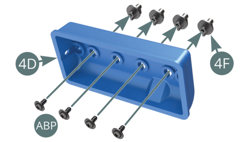
Position the four spark plugs (4F) on the cylinder head (4D) and secure each one with an ABP screw.
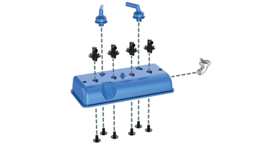
Step 3
Position the two air intake pipes (4G) on the cylinder head (4D) and secure each with an ABP screw.
Install the oil filler spout (4H) on the cylinder head (4D).
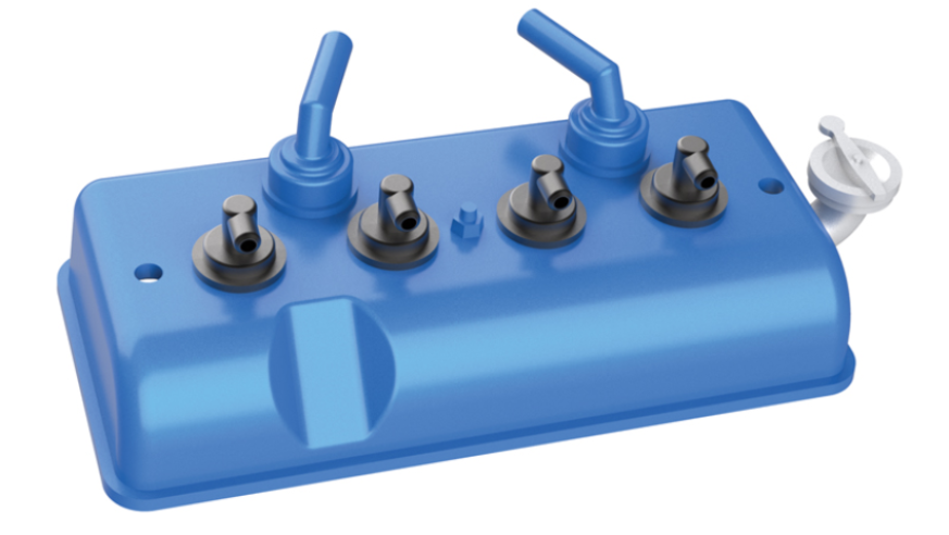
Pre-assembly of the cylinder head.

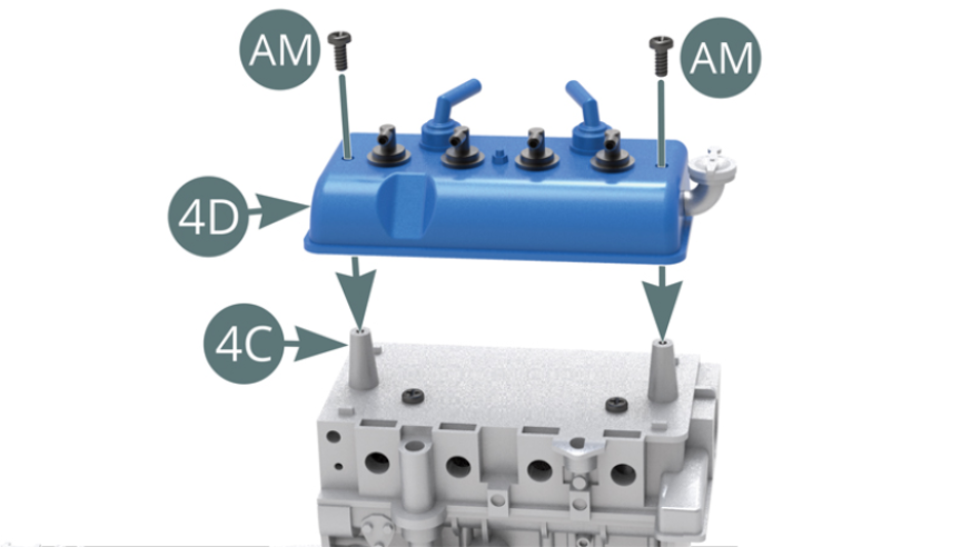
Step 4
Place the cylinder head (4D) on top of the engine block (4C) and secure with two AM screws.
ASSEMBLY DIAGRAM
GENERAL VIEW