English
 français
 Deutsch
 español
 italiano
 português


Box 10
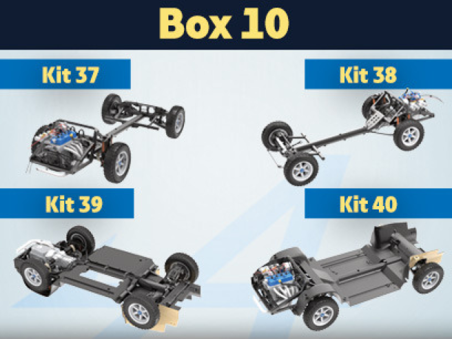
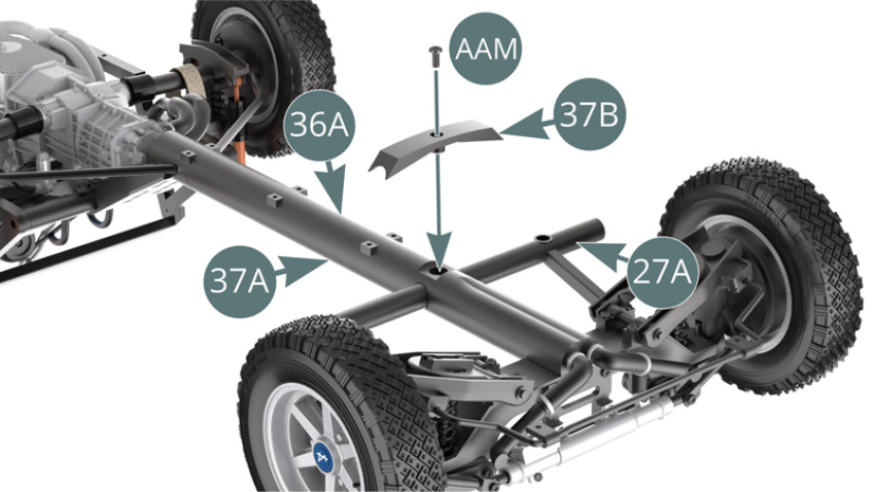
Kit 37 - Chassis assembly
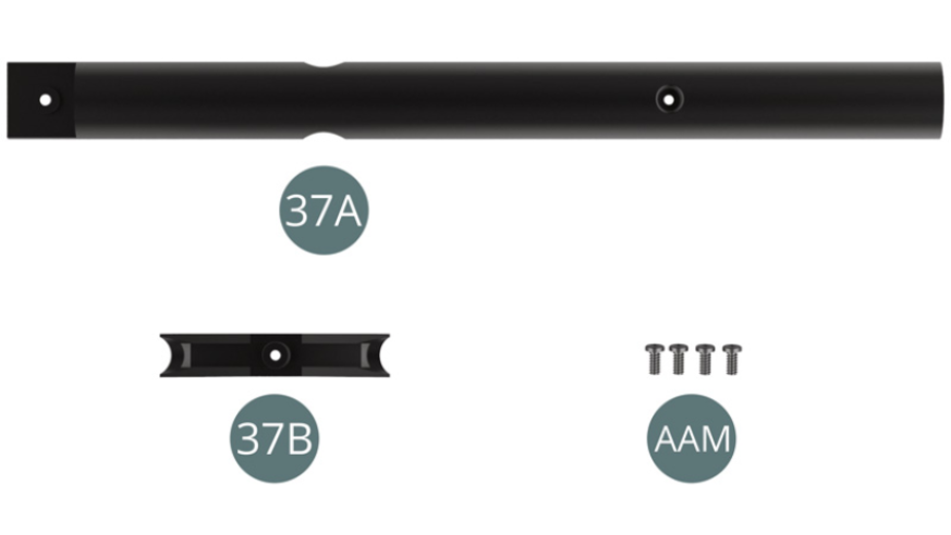
Parts of kit
- 37A Central beam chassis
- 37B Reinforcement plate
- AAM Screw M 2.3 x 5 mm (x 4)
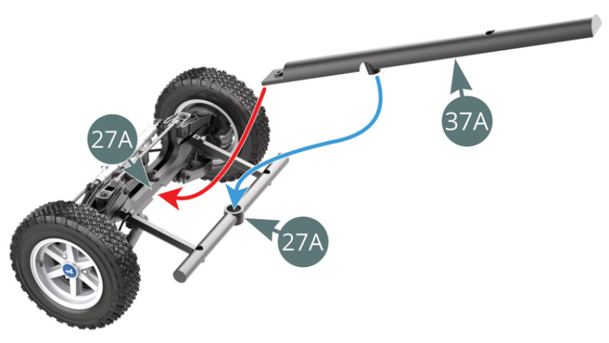
Step 1
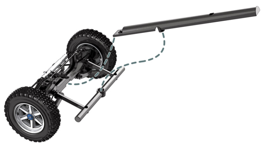
Position the central beam (37A) on the front frame cross bar (27A), firstly placing the end beneath the cross bar (red arrow) and then placing the nipple in the housing on the cross bar (blue arrow). Position the front frame cross bar (27A) and central beam (37A) on the central beam (36A).
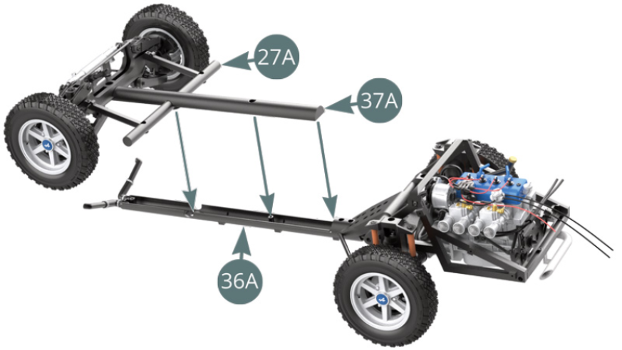
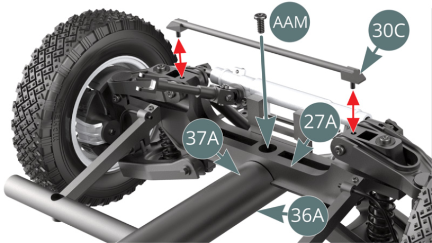
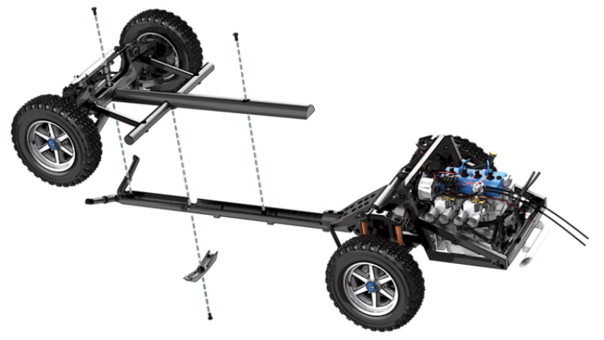
Step 2
Remove the upper bar (30C) - red arrows - and attach the centre beam sections (36A & 37A) to the front frame crossbar (27A) using an AAM screw. Reposition the upper bar (30C). A little further to the rear, fix the centre beam sections (36A & 37A) together using an AAM screw.

Step 3
Flip the chassis over and position the reinforcement plate (37B) on the central beam (36A), then attach it to the central beam (37A) using an AAM screw.
ASSEMBLY DIAGRAM
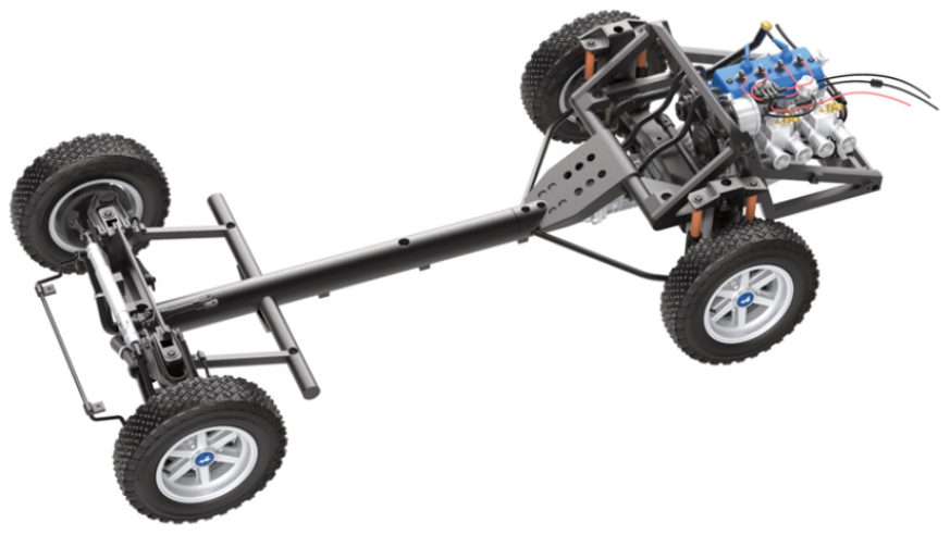
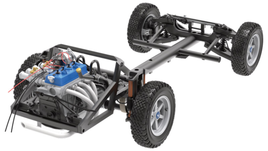
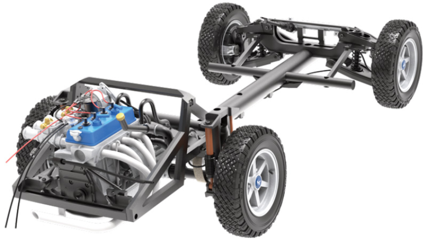
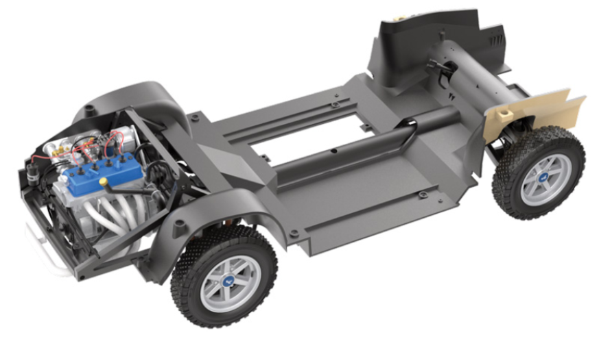
GENERAL VIEW
Kit 38 - Attaching the brake fluid lines to the chassis
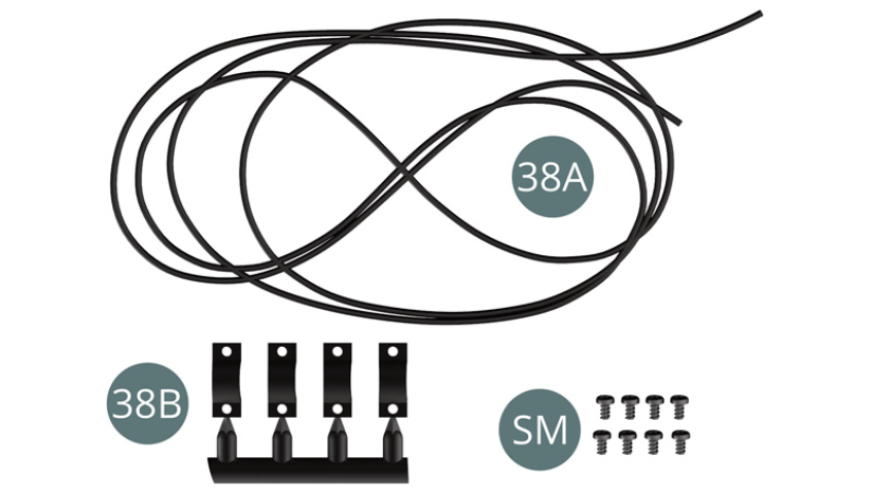
Parts of kit
- 38A Brake fluid line
- 38B Mounting bracket (x 4)
- Screw SM M 1.7 x 3 mm (x 80)
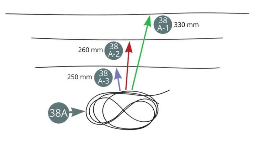
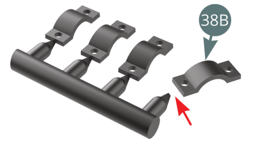
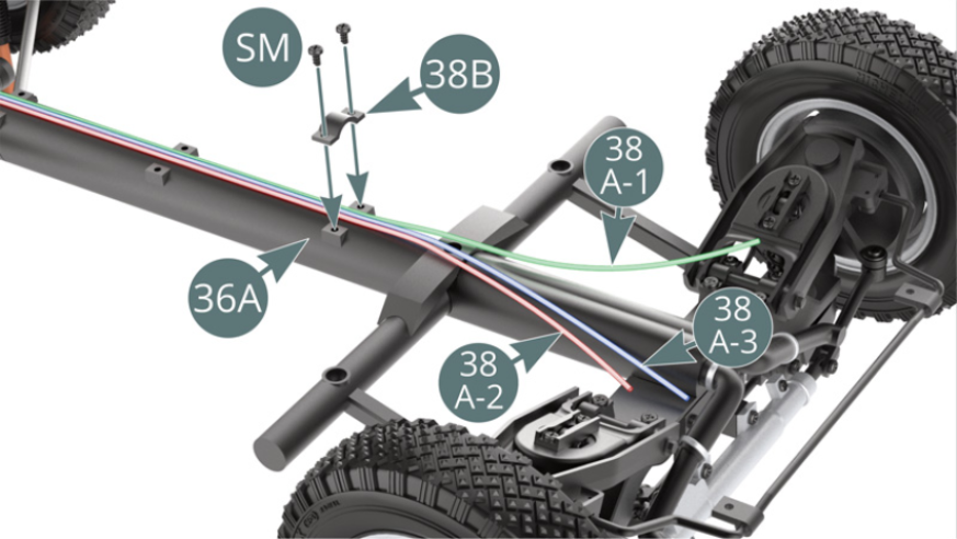
Step 1
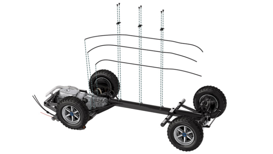
Cut the brake fluid line (38A) into three separate lengths: 38A-1 = 330 mm, 38A-2 = 260 mm and 38A3 f= 250 mm. Remove three mounting brackets (38B) from the sprue (the 4th is a spare part). Arrange the three brake fluid line sections 38A-1 (long), 38A-3 (short) and 38A-2 (medium) along the centre beam (36A) and hold them in place with a bracket (38B) secured by two SM screws.
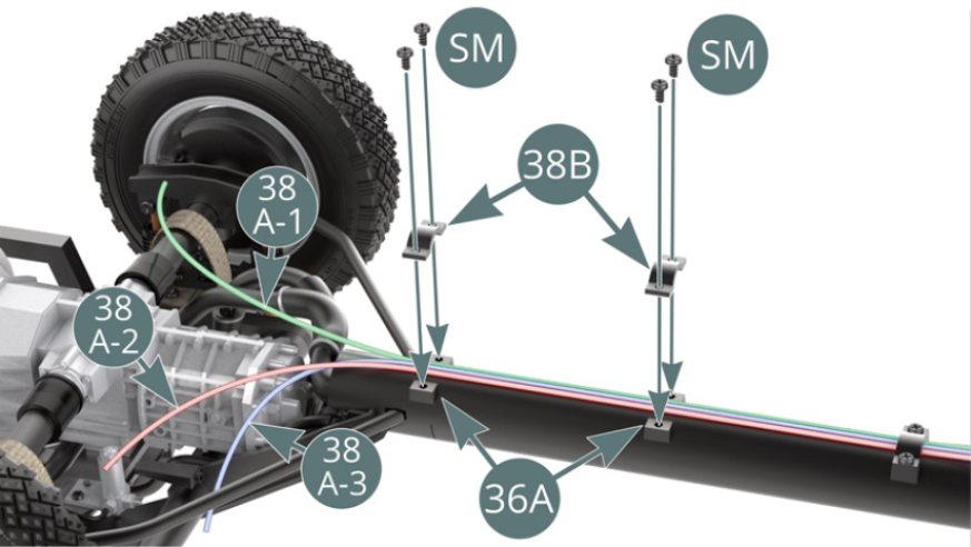
Step 2
Then attach the three brake fluid line sections (38A-1/long), (38A-3/short) and (38A-2/medium) a little further along the centre beam (36A) using two other brackets (38B) and four SM screws - shown above.
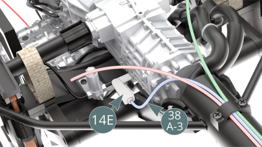
Step 3
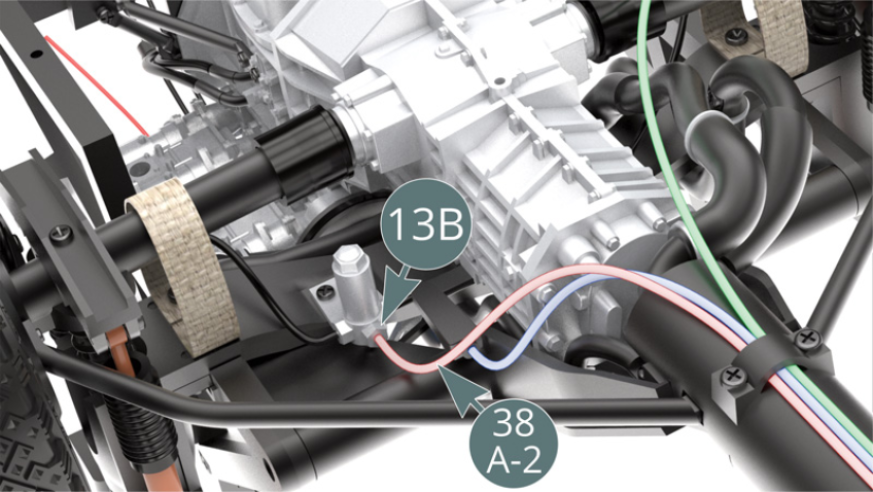
Position line (38A-3) - highlighted in blue - on the gear selector rod (14E). Position line (38A-2) - highlighted in red - onto the brake master cylinder (13B).
Step 4
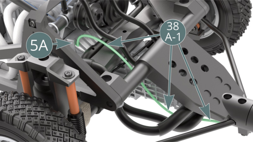
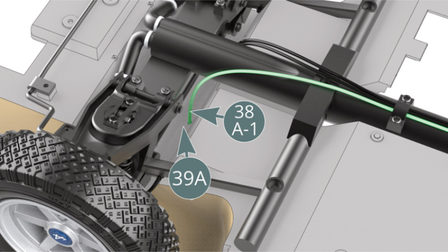
Turn the chassis over, then guide line (38A-1) - highlighted in green - and place it in the recess provided at the top of the gearbox housing (5A).
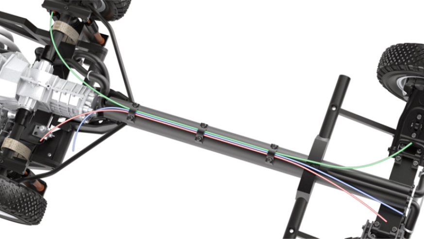
ASSEMBLY DIAGRAM
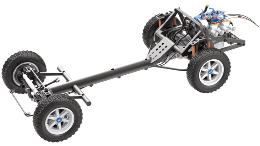
GENERAL VIEW
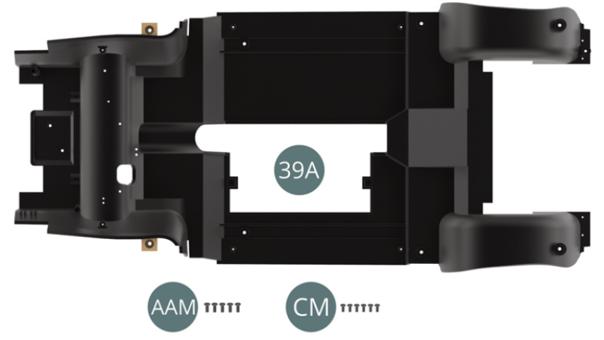
Kit 39 - Fixation du plancher du châssis sur le châssis-poutre
Parts of kit
- 39A Chassis floor
- Screw AAM M 2.3 x 5 mm (x 5)
- Screw CM M 2.0 x 4 mm (x 6)
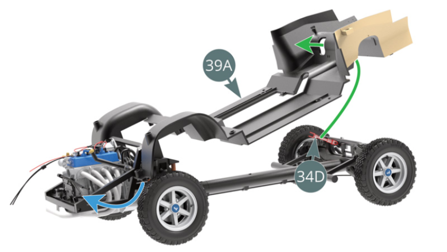
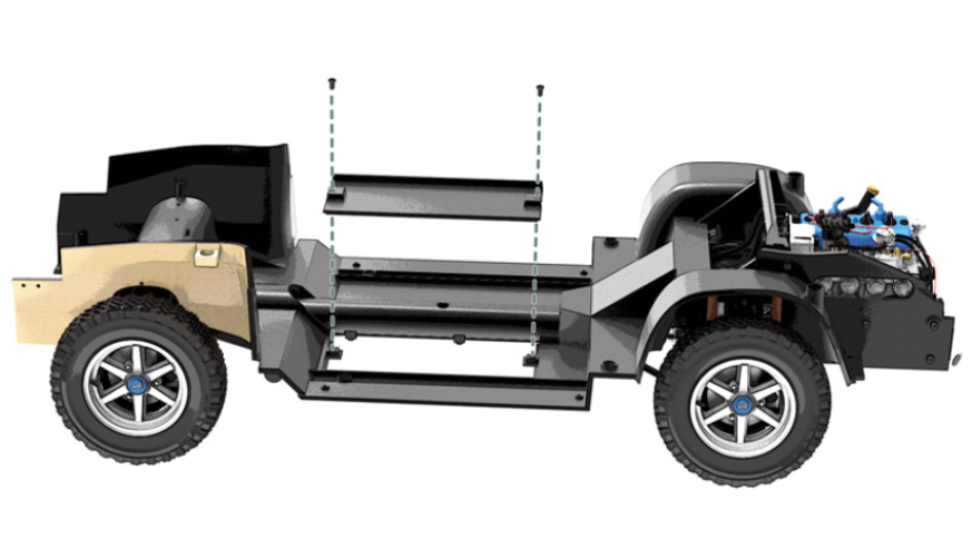
Step 1
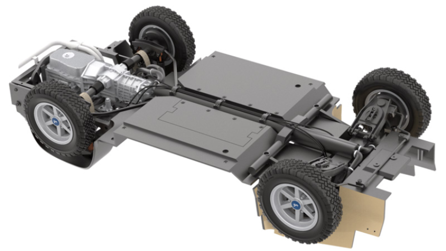
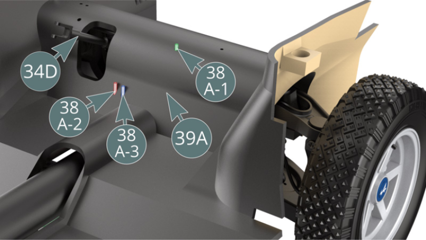
Start by positioning the chassis floor (39A) on the pre-assembled chassis beam as indicated by the blue arrow. Ensure that the intermediate shaft (34D) passes correctly through the aperture at the rear of the chassis floor (39A) - green arrow. Place brake fluid lines (38A-2 & 38A-3) underneath the front bottom of the chassis into the slots on the left side of chassis floor (39A).

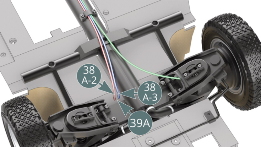
Step 2
Position brake fluid line (38A-1) into the slot on the right side of chassis floor (39A). Check the correct position of the lines from the other side of the chassis as shown in the illustration above.
Step 3
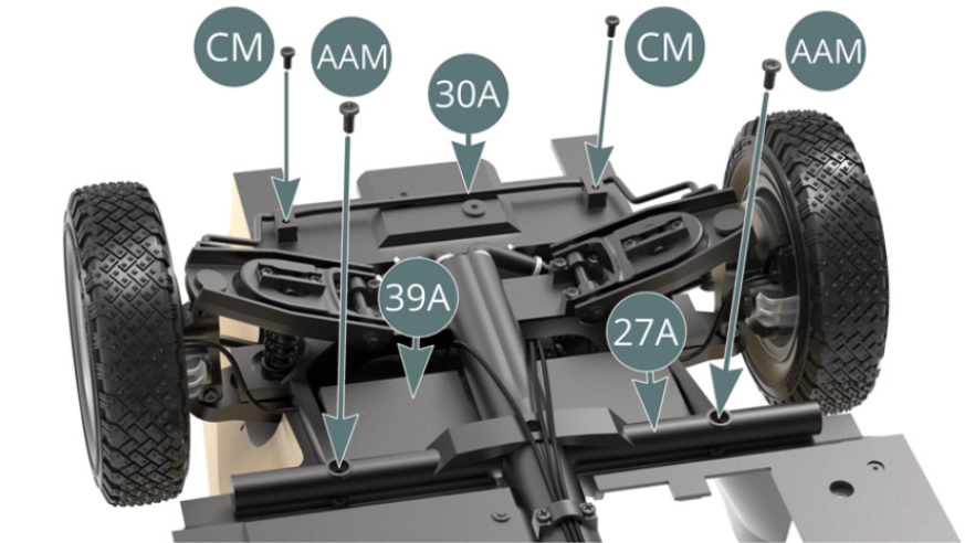
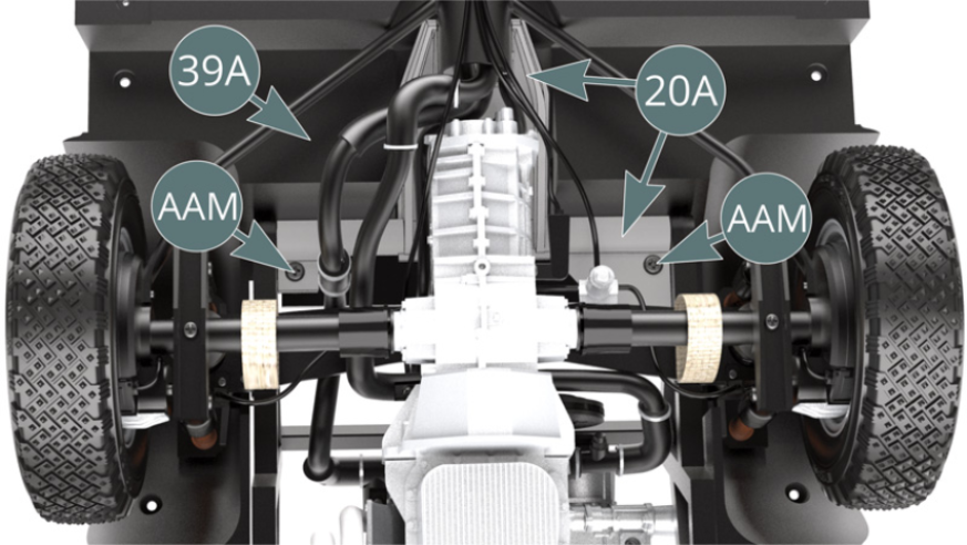
Fix the anti-roll bar (30A) and the front frame cross bar (27A) to the chassis floor (39A), using two CM and two AAM screws respectively. Secure the main frame (20A) to the chassis floor (39A) below the rear bottom of the chassis using two AAM screws.
Step 4
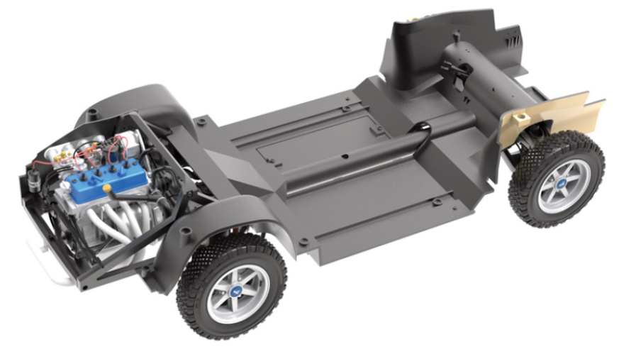
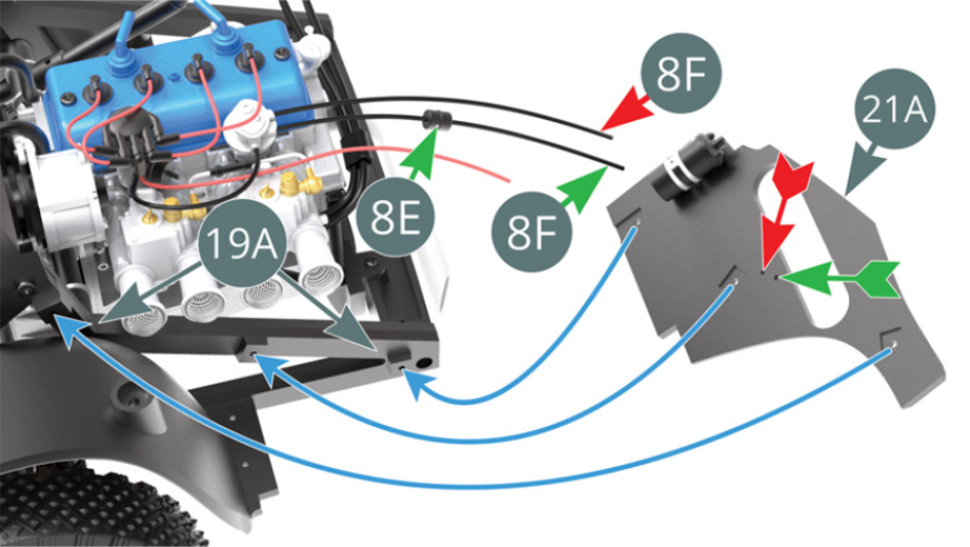
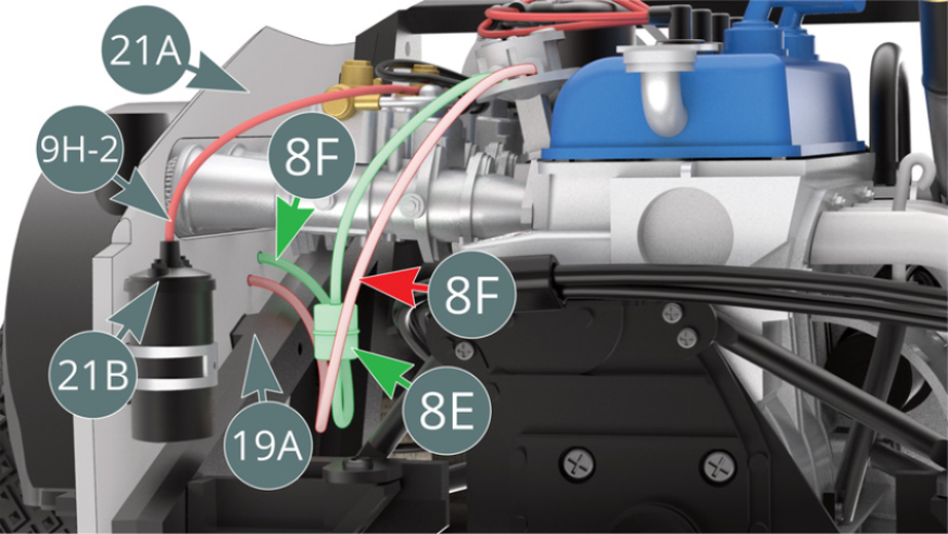
Position oil line (8F) together with oil filter (8E) - green arrows - and single oil line (8F) - red arrow - into the slots indicated by the arrows of their respective colours on the left engine compartment panel (21A). Position the left panel (21A) on the left frame (19A) - blue arrows. Position high voltage cable (9H-2) on ignition coil (21B).
Step 5
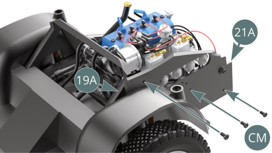
Fix the left engine compartment panel (21A) to the left frame (19A) by using three CM screws. Close-up of the assembly
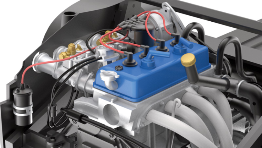
ASSEMBLY DIAGRAM
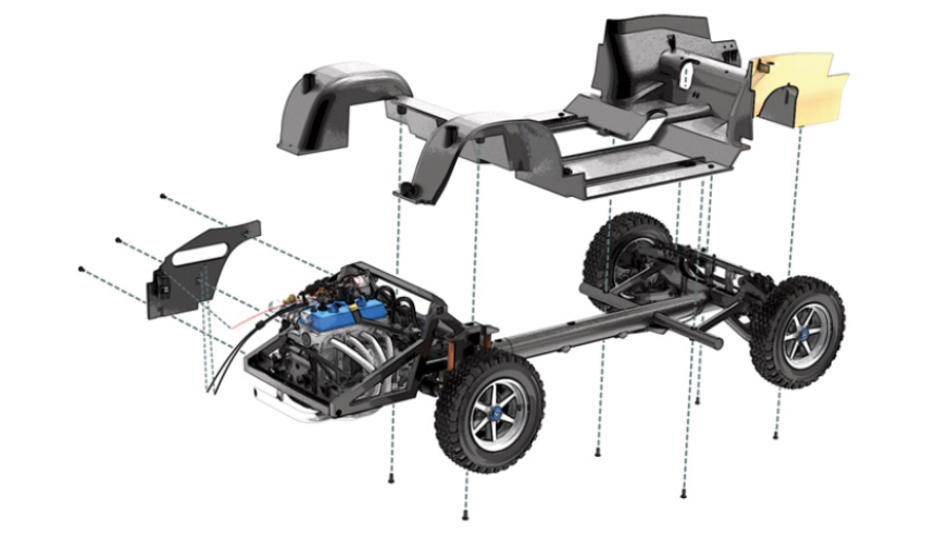
GENERAL VIEW

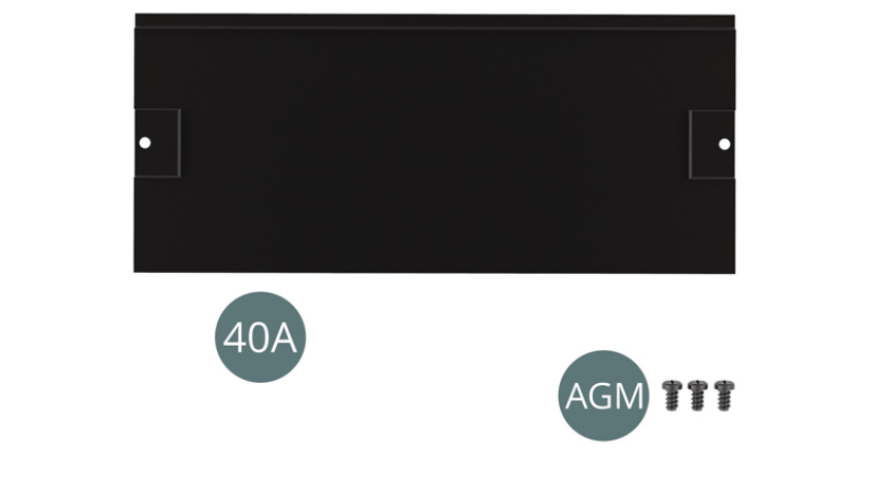
Kit 40 - Assembly of the floor panel
Parts of kit
- 40A Floor panel
- Screw AGM M 2.0 x 3 mm (x 3)
Step 1
Place the floor panel (40A) on the chassis floor (39A).
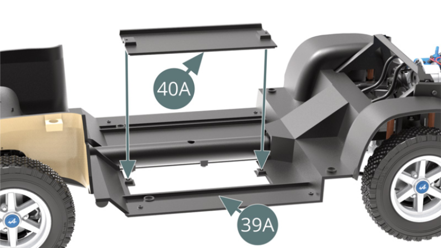
Fasten the floor panel (40A) to the chassis floor (39A) using two AGM screws.

ASSEMBLY DIAGRAM
GENERAL VIEW