English
 français
 Deutsch
 español
 italiano
 português


BOX 12
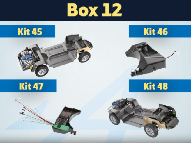
Kit 45 - Assembly and mounting of fuse box and tanks
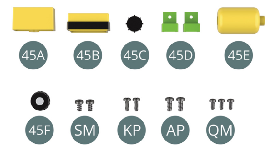
Parts of kit
- 45A Washer fluid tank base
- 45B Washer fluid tank top
- 45C Cap
- 45D Fuse box (x 2)
- 45E Expansion tank
- 45F Cap
- Screw SM M 1.7 x 3 mm (x 2)
- Screw KP M 1.4 x 4 mm (x 2)
- Screw AP M 1.7 x 4 mm (x 2)
- Screw QM M 1.4 x 3 mm (x 3)
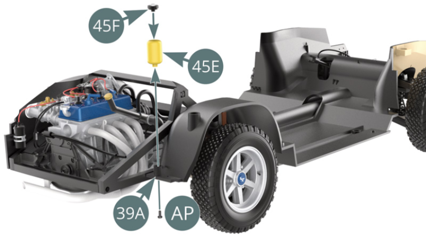
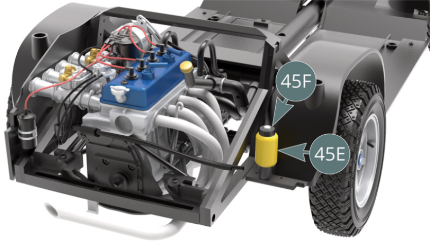
Step 1
Place the cap (45F) on the expansion tank (45E). Position the expansion tank (45E) on the floor of the chassis (39A) and secure it from below using an AP screw (see illustrations opposite and below).
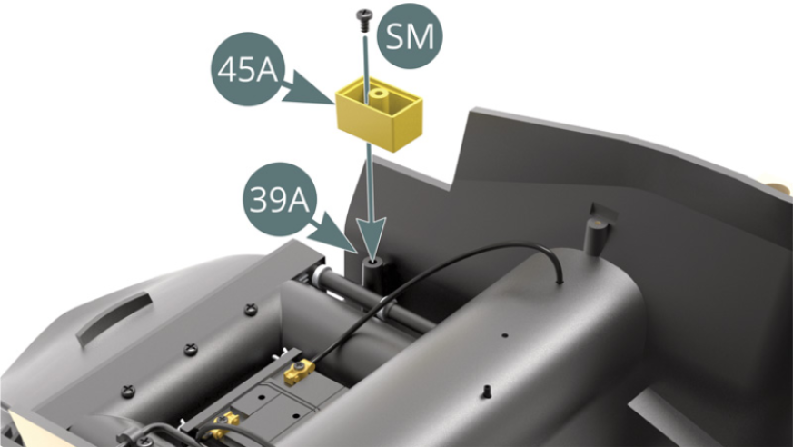
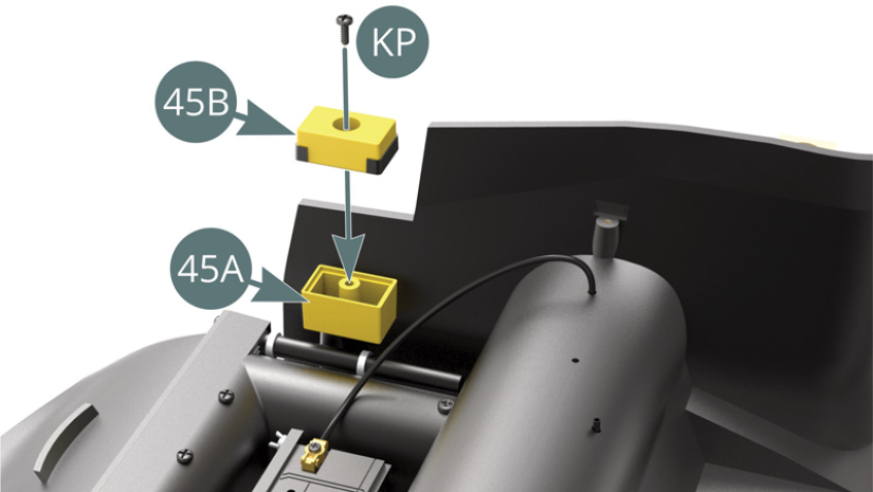
Step 2
Position the base of the windscreen washer fluid tank (45A) on the edge of the chassis floor (39A) and secure with a SM screw. Position the top of the washer fluid tank (45B) on the tank base (45A) and secure with a KP screw.
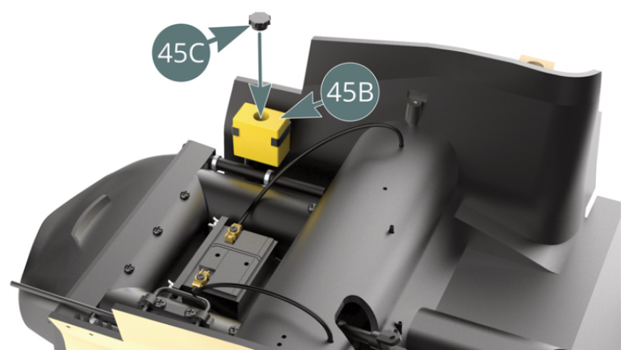
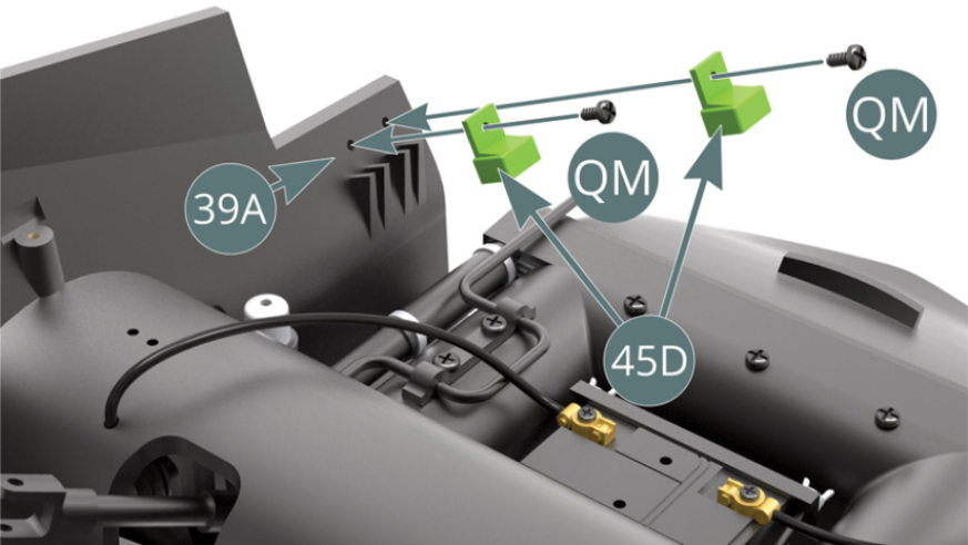
Step 3
Position the cap (45C) on top of the windscreen washer fluid tank (45B). Position the two fuse boxes (45D) on the edge of the chassis floor (39A) and secure each with a QM screw.
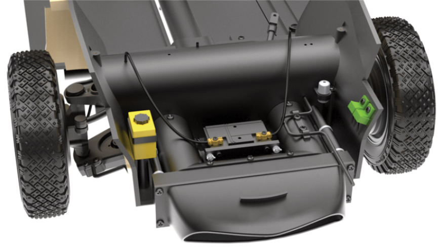
Step 4
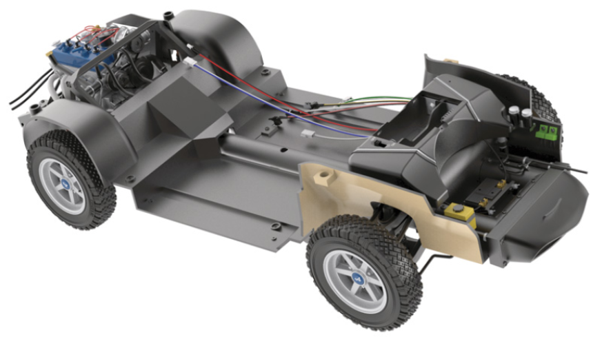
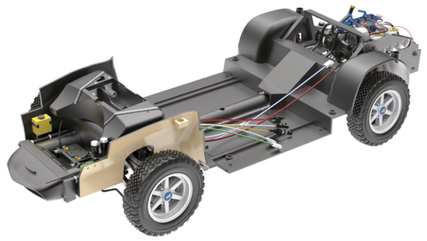
The windscreen washer fluid tank and fuse boxes are now installed at the front of the car.
ASSEMBLY DIAGRAM
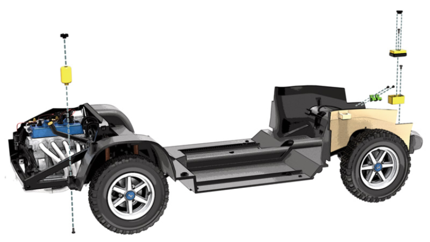
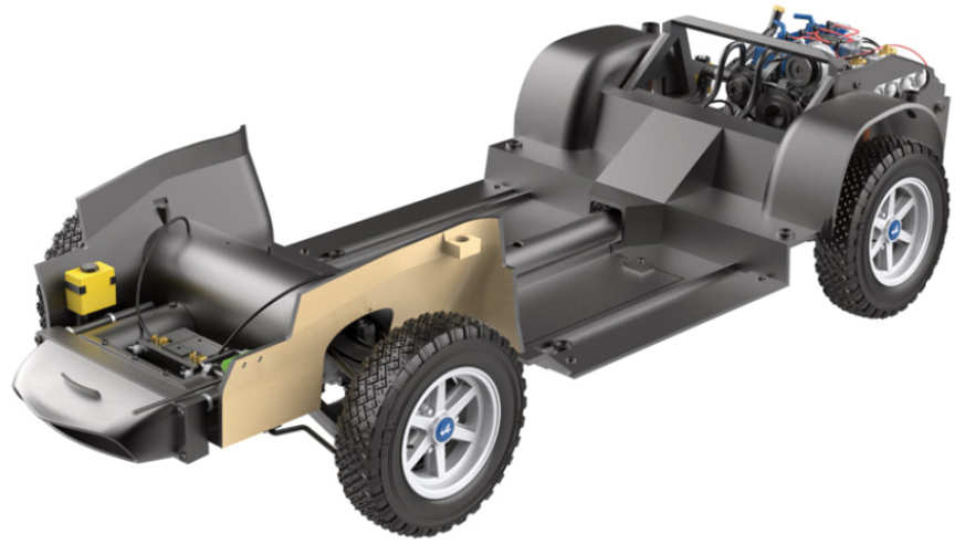
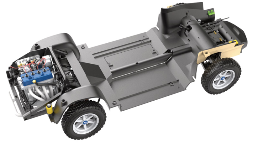
GENERAL VIEW
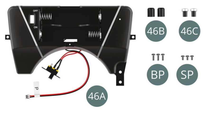
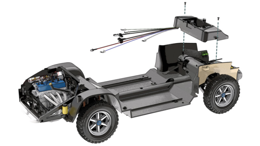
Kit 46 - Assembly and installation of fuel tank and brake fluid reservoirs
Parts of kit
- 46A Fuel tank
- 46B Brake fluid tank (x 2)
- 46C Brake fluid tank cap (x 2)
- Screw BP M 1.7 x 5 mm (x 3)
- Screw SP M 1.7 x 3 mm (x 3)
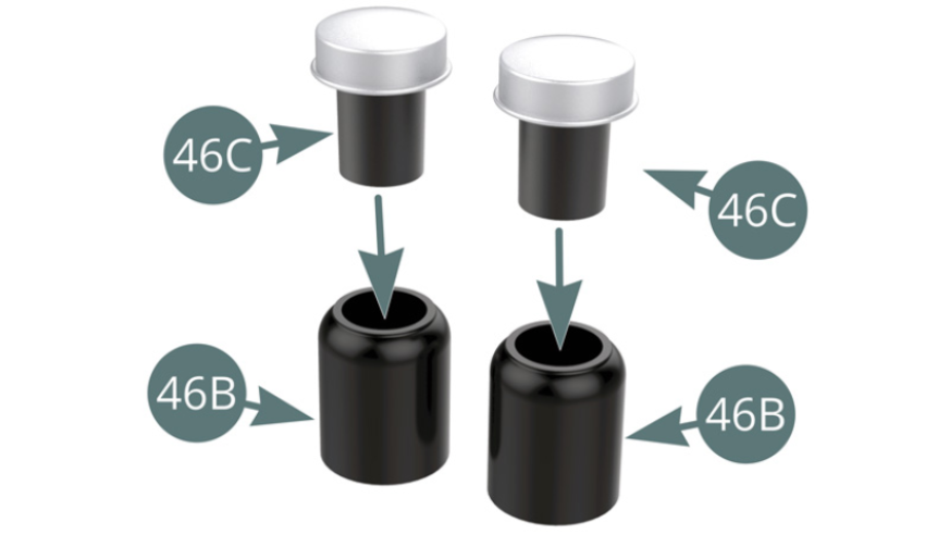
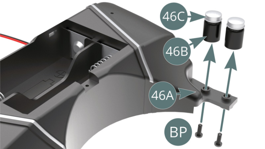
Step 1
Fit the two caps (46C) onto the brake fluid tanks (46B).
Step 2
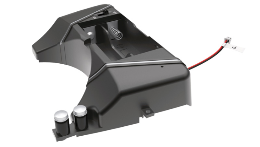
Position the two brake fluid tanks (46B) on the mounting supports located on the fuel tank (46A) and secure them from below using two BP screws.
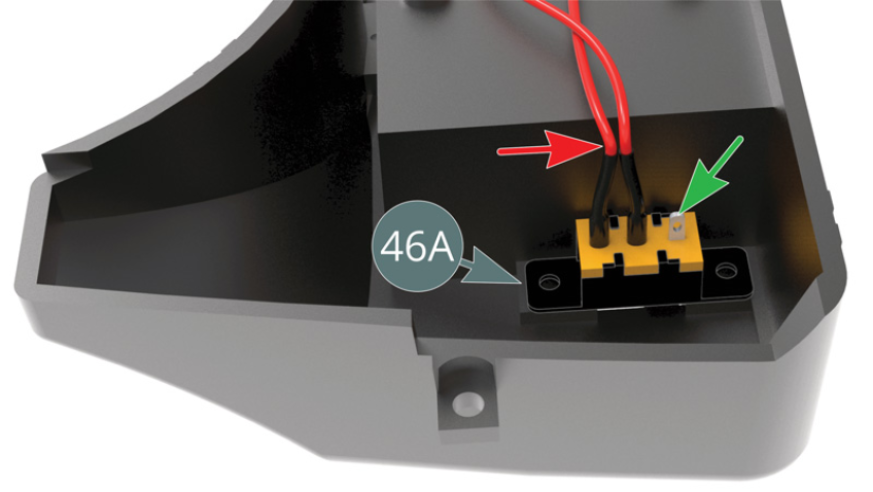
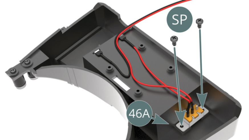
Step 3
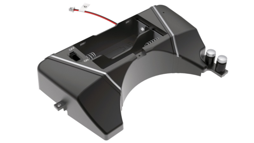
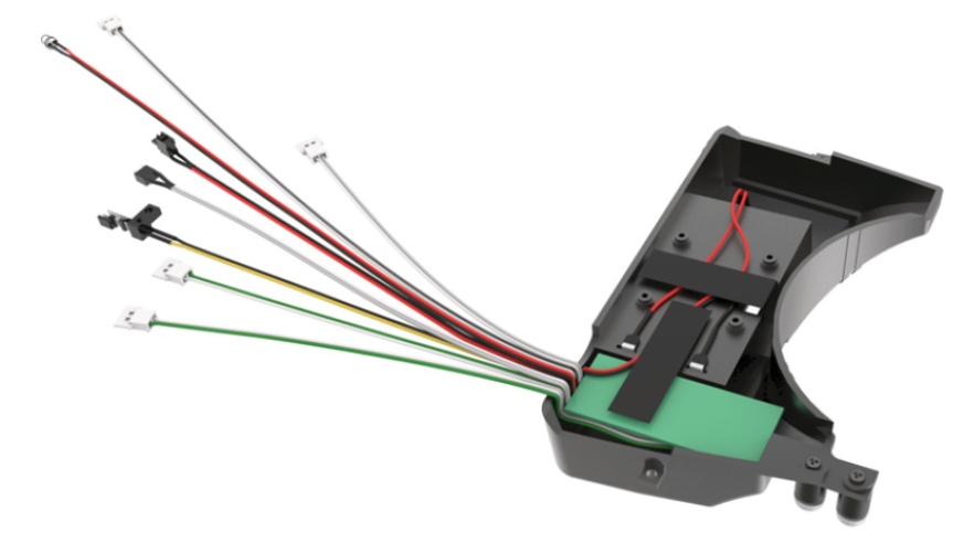
Install the switch in the slot located on the fuel tank (46A). Check the correct orientation of the two red wires (red arrow) and the connector (green arrow). Secure the switch with two SP screws (shown above).
ASSEMBLY DIAGRAM
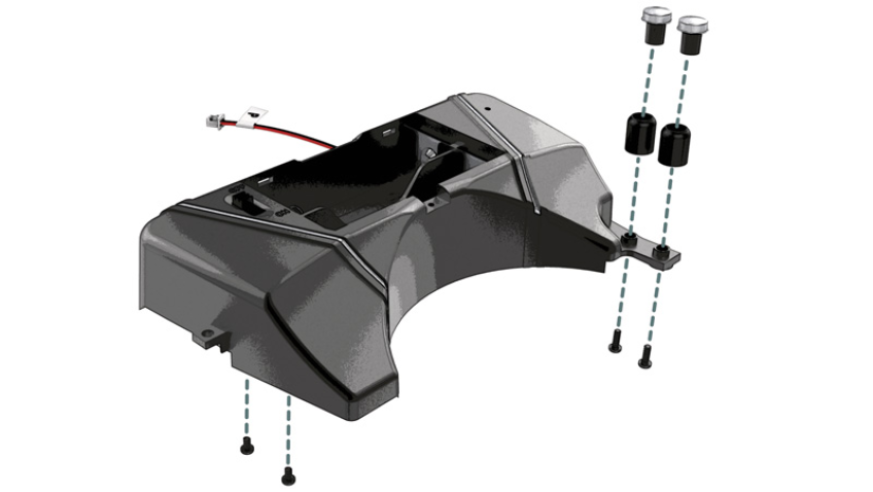
GENERAL VIEW
Kit 47- PCB installation and wiring
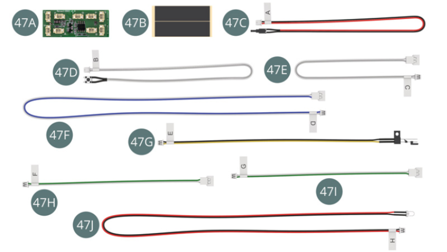
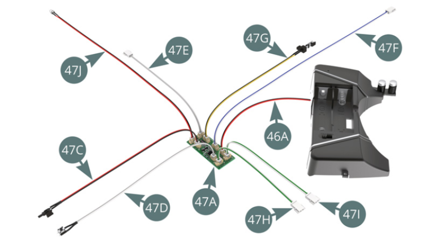
Parts of kit
- 47A PCB
- 47B Adhesive tape (x 2)
- 47C Switch cable A (red - black)
- 47D Switch cable B (grey - white)
- 47E Cable C (grey - white)
- 47F Cable D (blue - white)
- 47G Switch cable E (yellow - black)
- 47H Cable F (green - white)
- 47I Cable G (green - white)
- 47J LED cable H (red - black)
Step 1
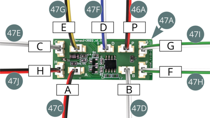
Connect (clockwise) the following cables in their respective slots indicated by a marking of the corresponding letter on the PCB: cable A from switch (47C), cable H from LED (47J), cable C (47E), cable E from switch (47G), cable D (47F), cable P from tank (46A), cable G (47I), cable F (47H) and cable B from switch (47D) - illustrations opposite and below.
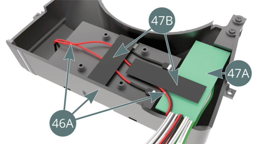
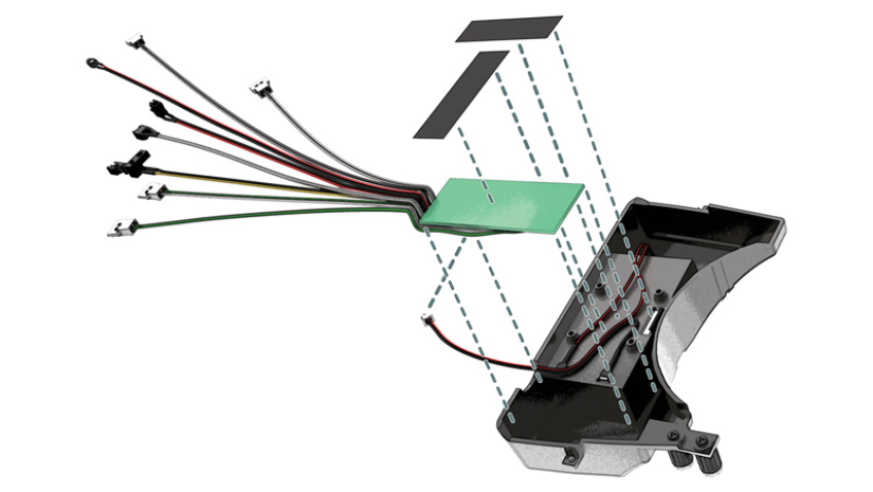
Step 2
Turn the fuel tank (46A) upside down and carefully position the PCB (47A) - with the connected cables - in the recess on the side. Secure the arrangement of cable (46A) and PCB (47A_ with two pieces of adhesive tape (47B).
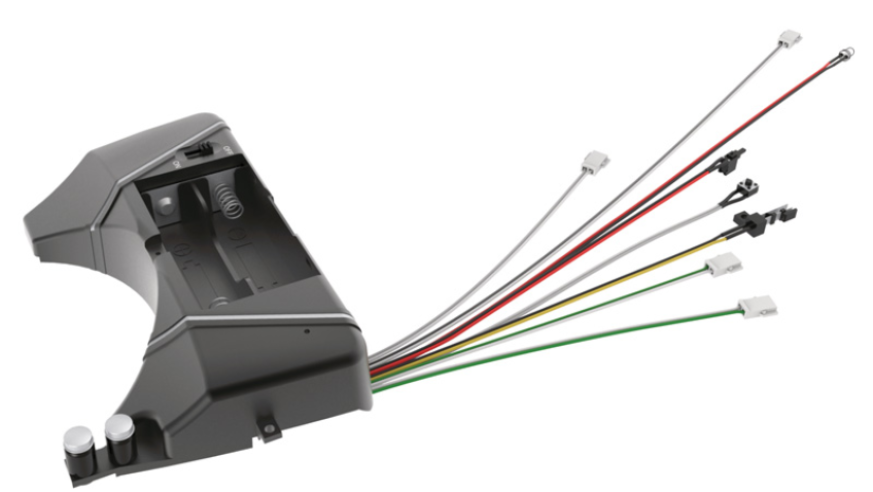
ASSEMBLY DIAGRAM
GENERAL VIEW
Kit 48 - Test of the PCB and installation of the fuel tank on the chassis
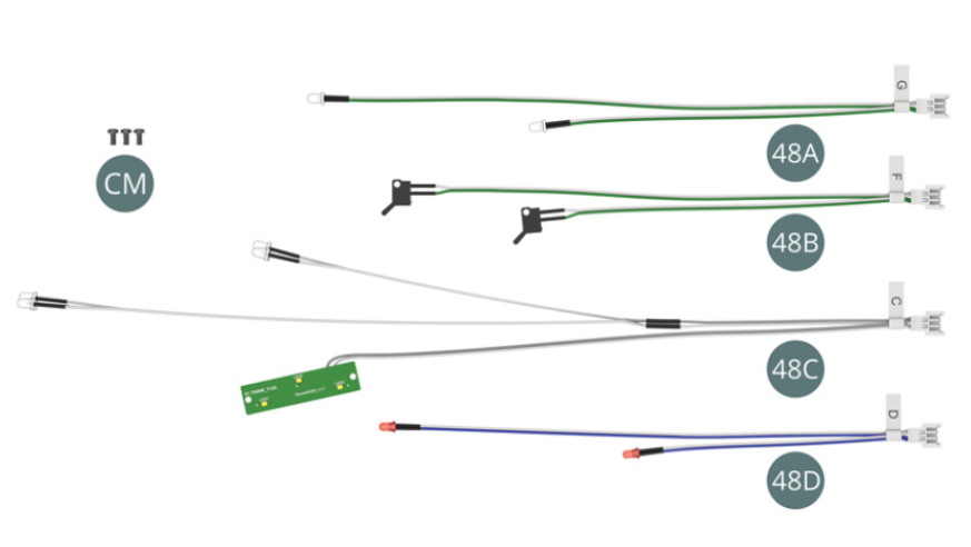
Parts of kit
- 48A LED cable G (green - white)
- 48B Door switch cable F (green - white)
- 48C LED cable C (grey - white)
- 48C LED cable D (blue - white)
- Screw CM M 2.0 x 4 mm (x 3)
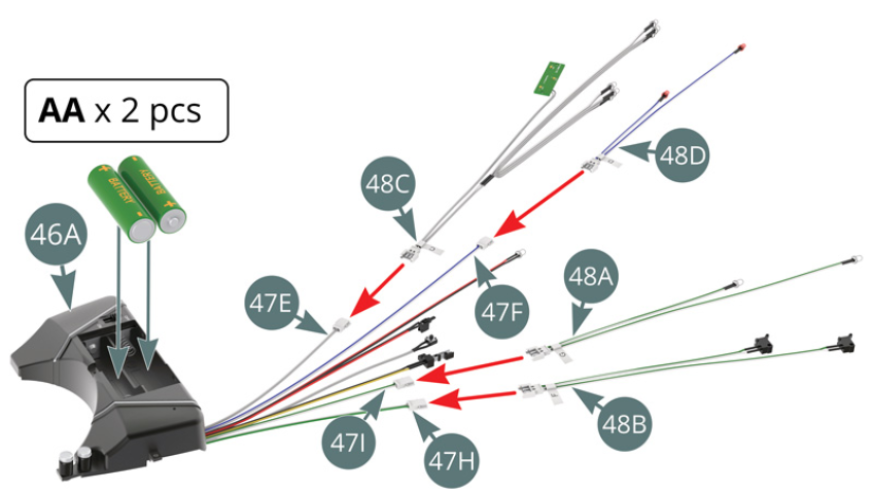
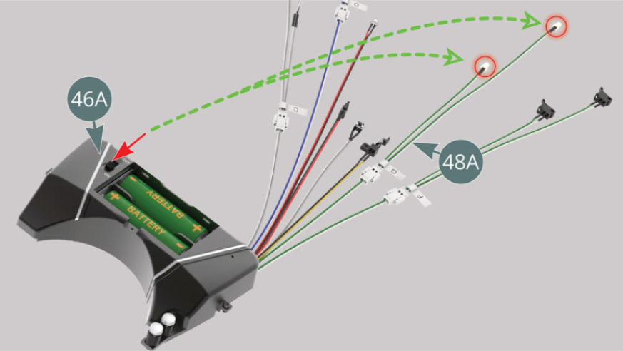
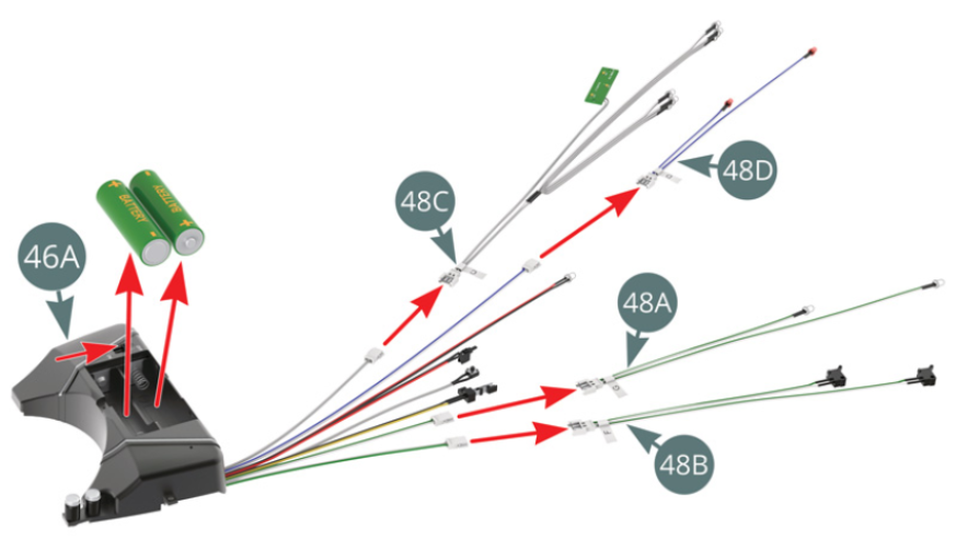
Step 1
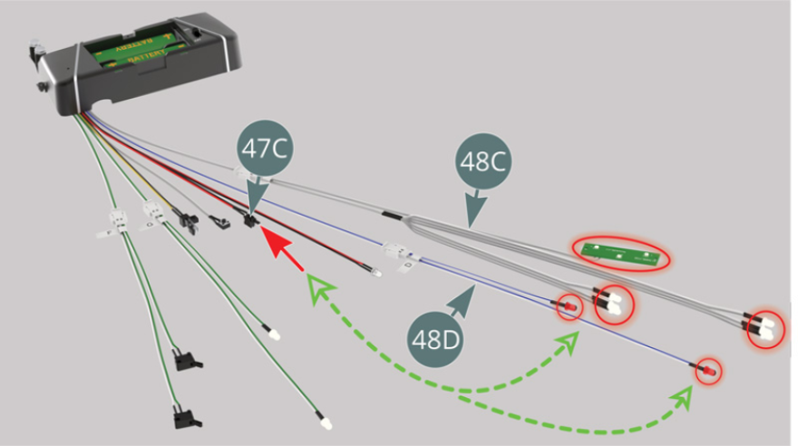
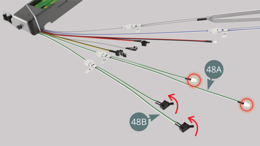
Connect LED cable C (48C) to cable C (47E), LED cable D (48D) to cable D (47F), LED cable G (48A) to cable G (47I), and door switch cable F (48B) to cable F (47H). Insert two AA batteries (not supplied) in the battery compartment on the fuel tank (46A). Turn the switch on the battery compartment (46A) to ON and check that the two LEDs on cable G (48A) light up (green arrows).
Step 2
Turn on the switch for cable A (47C) and check that the lights on cable C (48C) - dashboard and cockpit - and those on cable D (48D) - taillights - light up, then flip the switch to turn them off. Turn on the switch for cable A (47C) to check that the Stop lights are working.
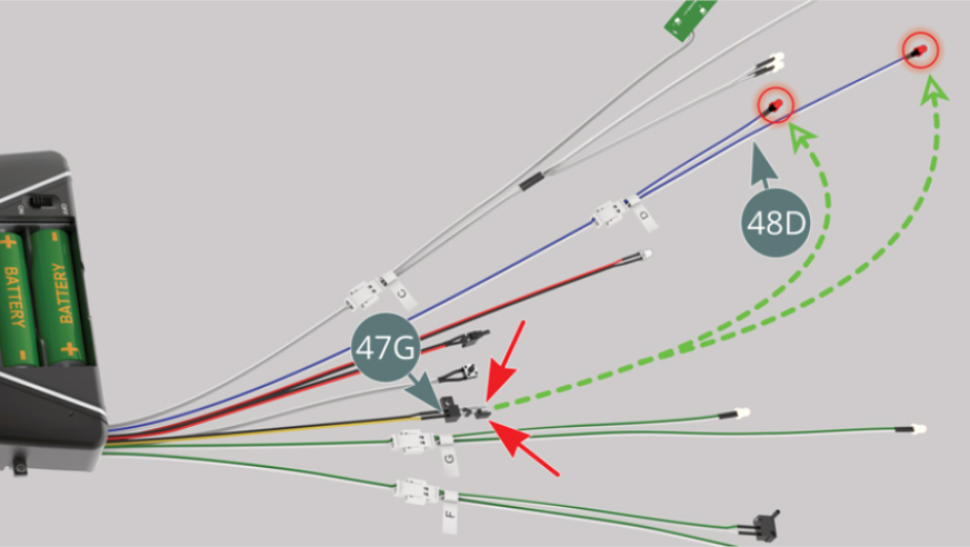
At the same time, turn on the switch of cable E black - yellow (47G) and check that the two red LEDs of cable D (48D) light up more brightly.
Step 3
Operate both switches of the door switch cable F (48B) simultaneously and check that two LEDs on cable G (48A) turn off - corresponding to the car with the doors closed and the passenger compartment light off.
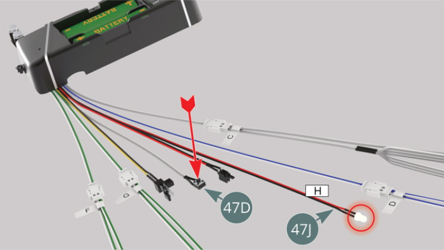
Operate the switch on cable B (47D) - red arrow - and check that the LED on cable H (47J) - reversing light - illuminates.
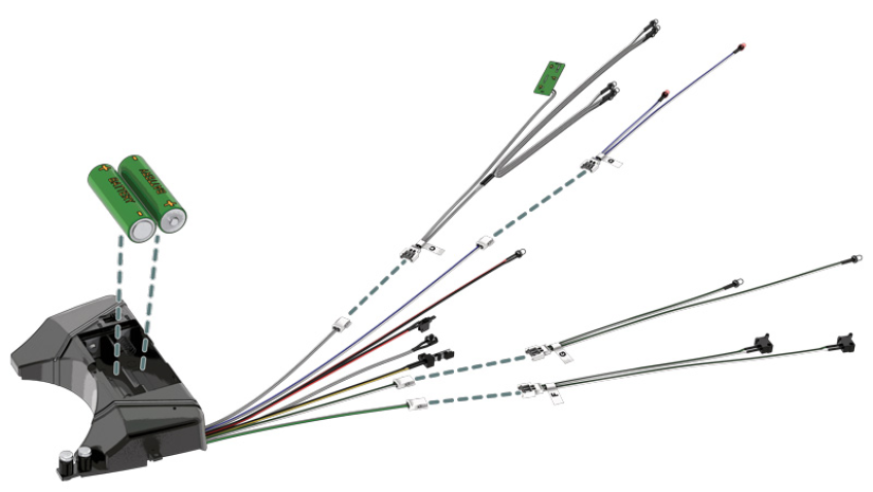
Step 4
Turn the battery compartment switch (46A) to OFF and remove the two AA batteries from their compartment for future use.
Disconnect LED cable C (48C), LED cable D (48D), LED cable G (48A), and door switch cable F (48B).
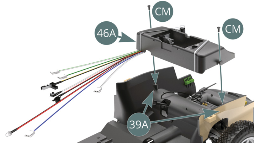
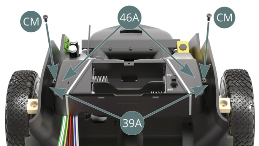
Step 5
Place the fuel tank (46A) on the chassis floor (39A) and secure it with two CM screws (shown above).
ASSEMBLY DIAGRAM
GENERAL VIEW