English
 français
 Deutsch
 español
 italiano
 português


Box 13
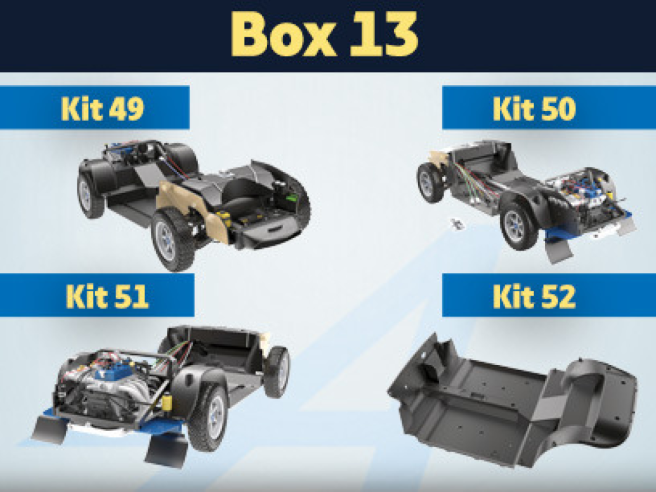
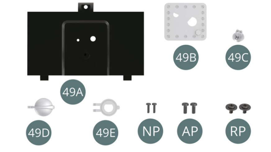
Kit 49 - Assembly and mounting of the battery cover
Parts of kit
- 49A Battery cover
- 49B Support plate
- 49C Fuel Gauge
- 49D Tank cap
- 49E Filling neck
- Screw NP M 1.2 x 4 mm (x 2)
- Screw AP M 1.7 x 4 mm (x 2)
- Screw RP M 1.7 x 3 x 5.5 mm (x 2)
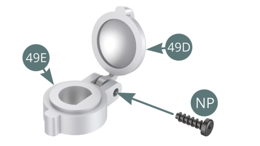
Step 1
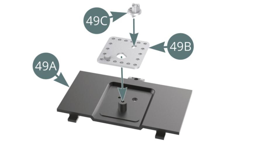
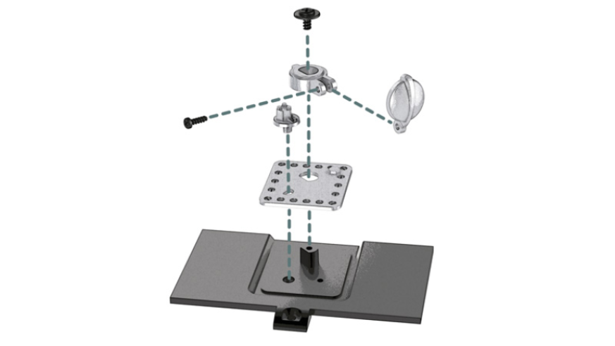
Position the tank cap (49D) on the filler neck (49E) and secure it with an NP screw. Position the fuel gauge (49C) on the support plate (49B), then position the latter on the battery cover (49A).
Step 2
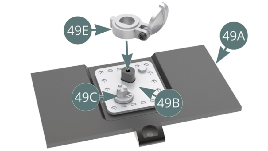
Position the filler neck (49E) on the battery cover (49A) above the support plate (49B).
Step 3
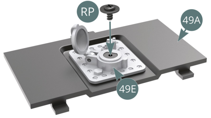
Secure the filler neck (49E) to the battery cover (49A) with a RP screw.
Step 4
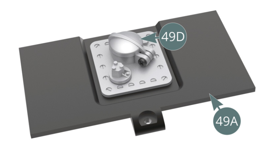
Close the tank cap (49D).
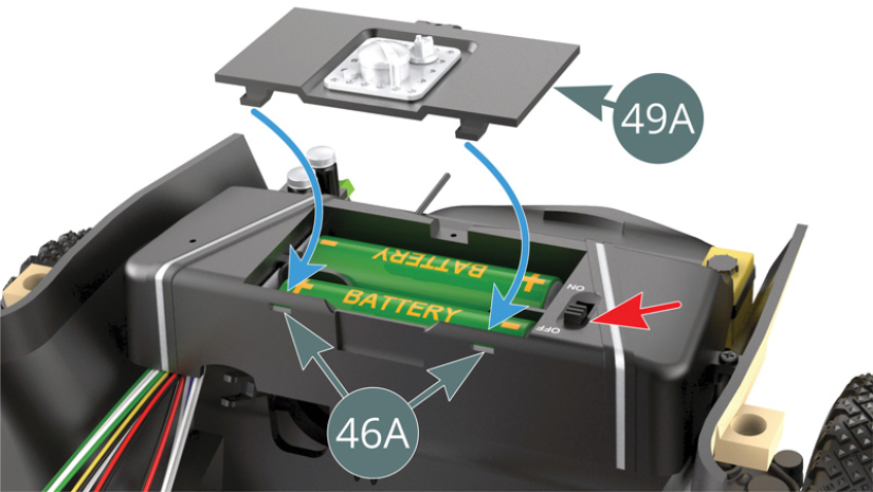
Step 5
Place two AA type batteries (not supplied) in the compartment located in the fuel tank (46A) and move the switch into the off position (red arrow). Place the battery cover (49A) on the fuel tank (46A) by engaging the tabs in the slots provided at the rear of the fuel tank (46A).
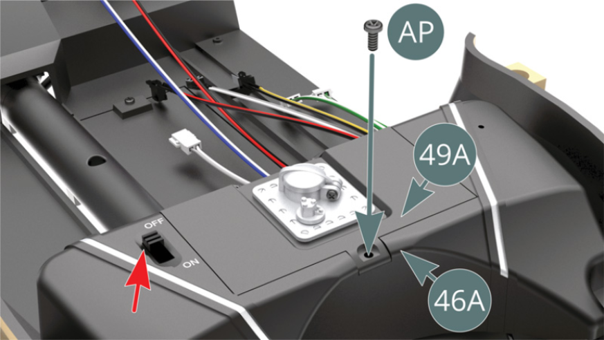
Step 6
Secure the battery cover (49A) to the fuel tank (46A) with an AP screw, be careful not to overtighten as not to damage the threading.
ASSEMBLY DIAGRAM

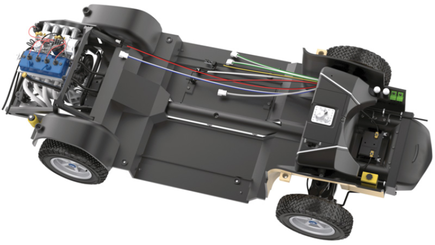
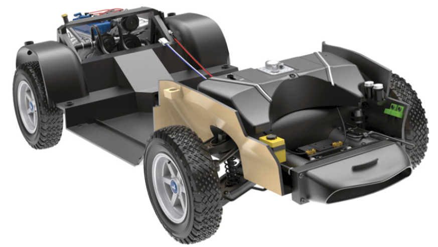
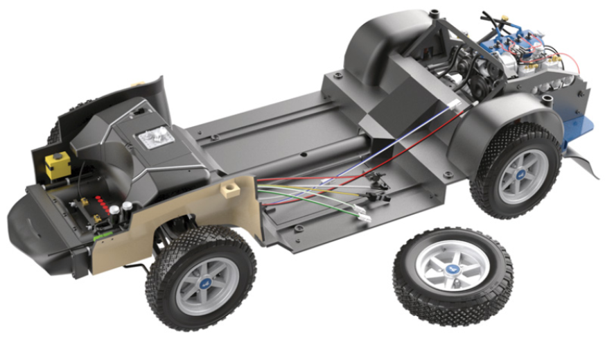
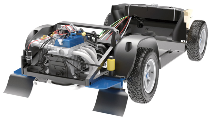
GENERAL VIEW
Kit 50 - Assembly of the jack, fitting of the rear panels and the mudguards
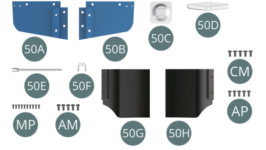
Parts of kit
- 50A Left rear panel
- 50B Right rear panel
- 50C Jack Base
- 50D Jack lever
- 50E Jack pivot
- 50F Jack support
- 50G Left mudguard
- 50H Right mudguard
- Screw MP M 1.2 x 3 mm (x 10)
- Screw AM M 1.7 x 4 mm (x 5)
- Screw CM M 2.0 x 4 mm (x 5)
- Screw AP M 1.7 x 4 mm (x 5)
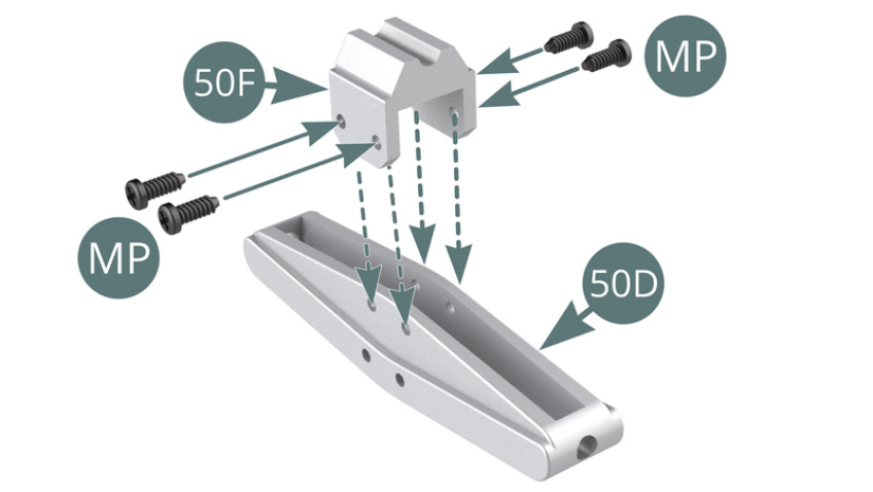
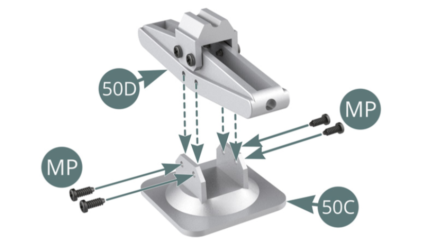
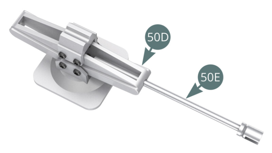
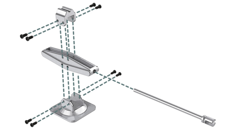
Step 1
Place the jack support (50F) on the jack lever (50D) and secure with two MP screws on each side. Position the jack lever (50D) on the jack base (50C) and secure it with two MP screws on each side.
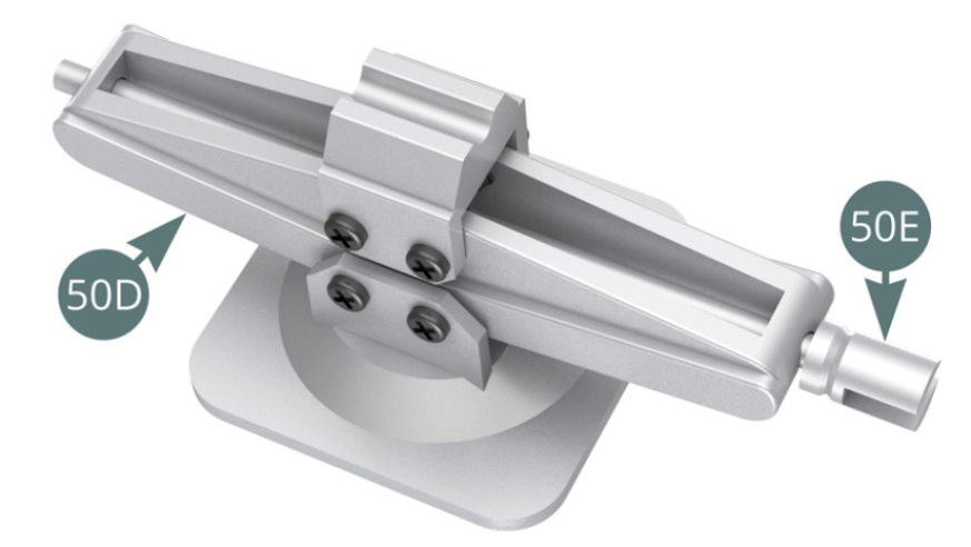
Step 2
Engage the jack pin (50E) through the two openings located at the ends of the jack lever (50D) - illustrations opposite and below.
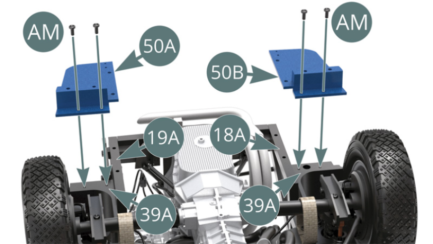
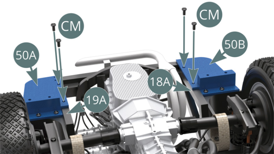
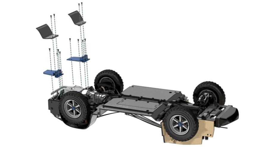
Step 3
Position the left rear (50A) and right rear (50B) panels, respectively onto the left (19A) and right (18A) frames, as well as on the chassis floor (39A), then secure each of them to the latter with two AM screws. Then attach the left rear (50A) and right rear (50B) panels to the left (19A) and right (18A) frames with four CM screws.
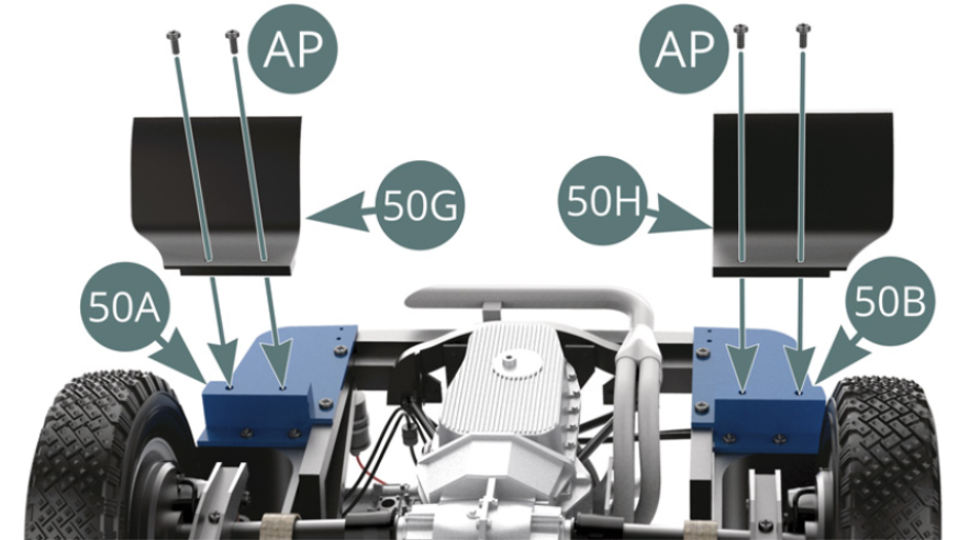
Step 4
Position the left (50G) and right (50H) mudguards, respectively on the edges of the left rear (50A) and right rear (50B) panels, and secure each of them with two AP screws.
Rear mudguards are now mounted to the frame.
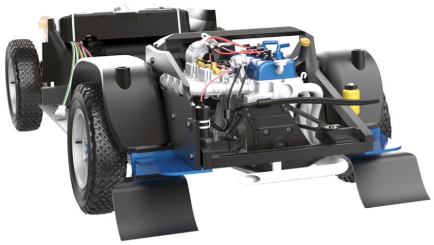
ASSEMBLY DIAGRAM
GENERAL VIEW
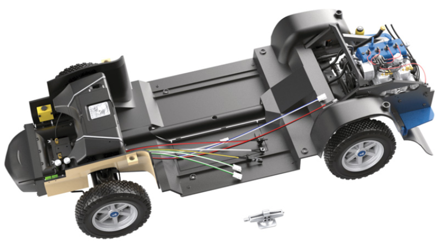
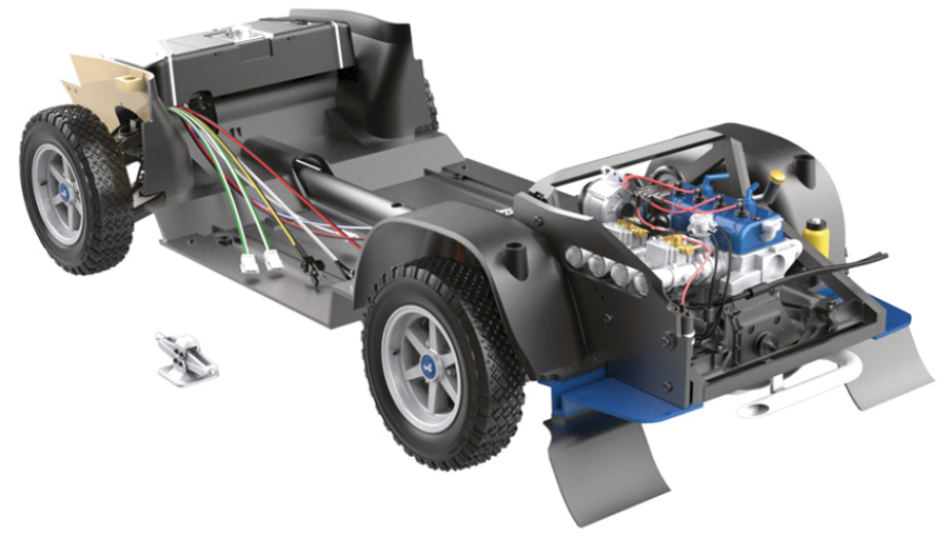
Kit 51 - Assembly of the spare wheel, application of the battery sticker and assembly of the breathers on the engine’s cylinder head
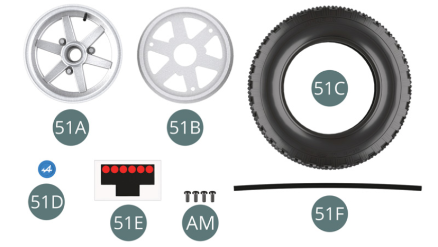
Parts of kit
- 51A Outer wheel rim
- 51B Inner wheel rim
- 51C Tyre
- 51D Hub cap
- 51E Battery Sticker
- 51F Breather hose
- Screw AM M 1.7 x 4 mm (x 4)
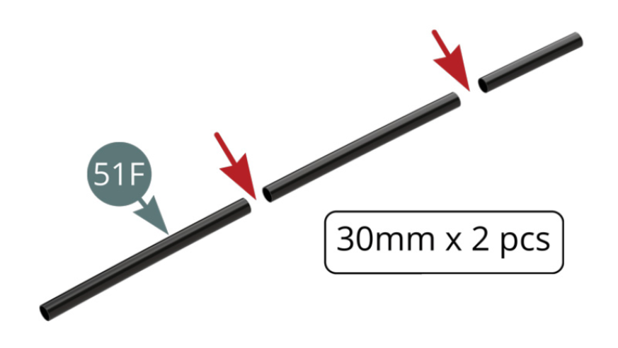
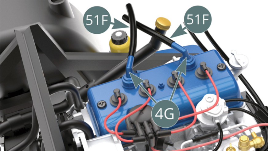
Step 1
Cut two pieces of 30mm each from the breather hose (51F). Position the two breather hoses (51F) on the air inlet pipes (4G).
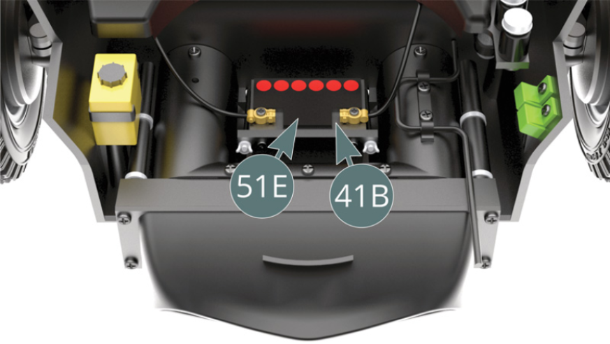
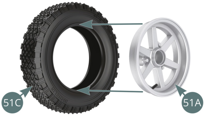
Step 2
Apply the sticker (51E) on the top of the battery (41B). Position the outer wheel rim (51A) in the tyre (51C).
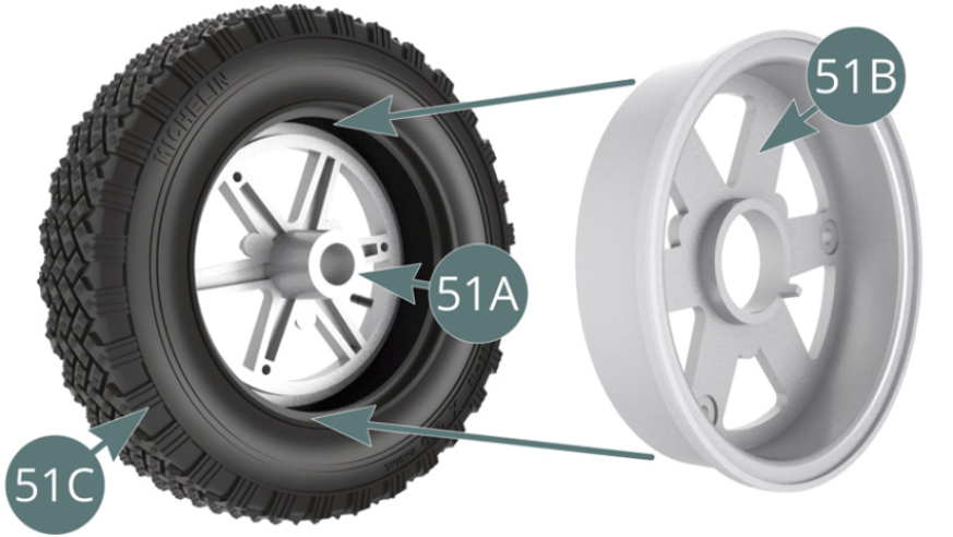
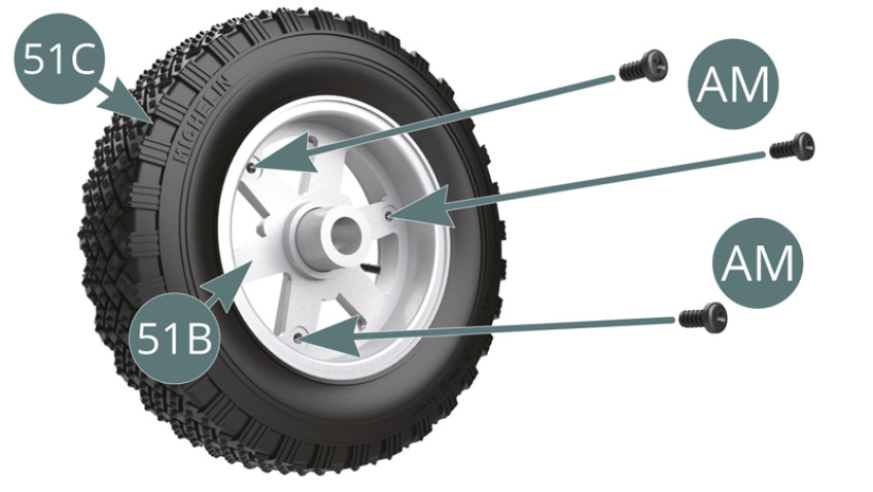
Step 3
Position the inner wheel rim (51B) into the tire (51C) aligning it with the outer rim (51A) and secure with three AM screws (illustrations opposite and below).
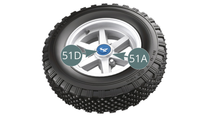
Step 4
Position the hub cap (51D) on the outer wheel rim (51A).
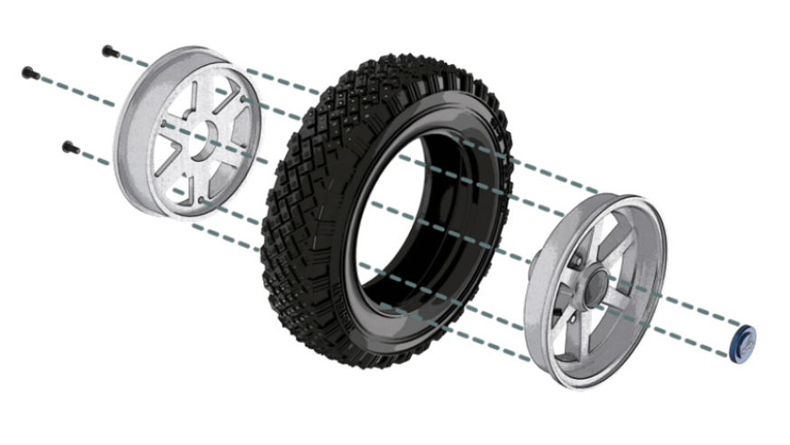
ASSEMBLY DIAGRAM
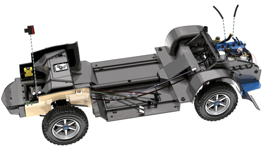
GENERAL VIEW
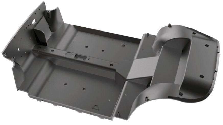
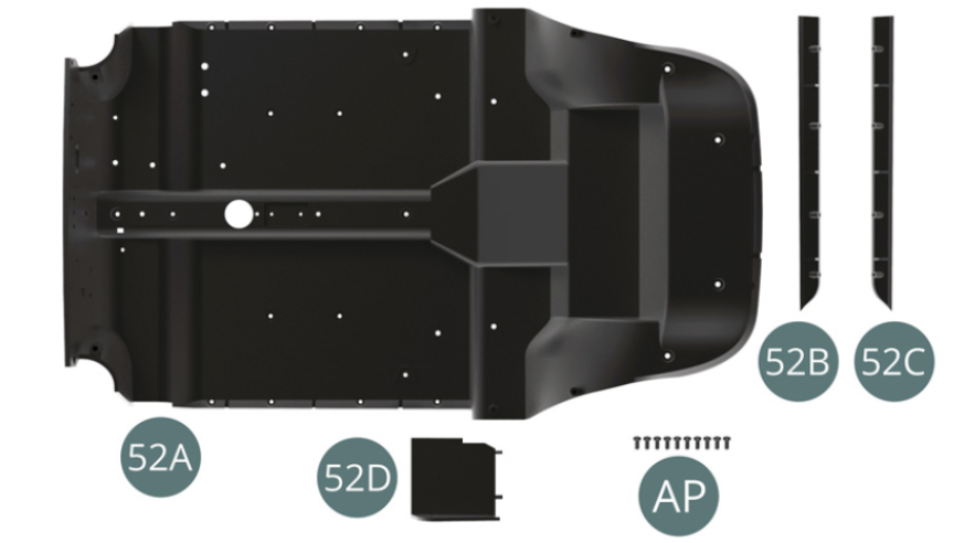
Kit 52 - Assembly of the cabin floor
Parts of kit
- 52A Cabin floor
- 52B Left lateral edge
- 52C Right lateral edge
- 52D Bulkhead
- Screw AP M 1.7 x 4 mm (x 10)
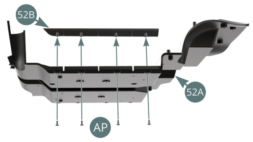
Step 1
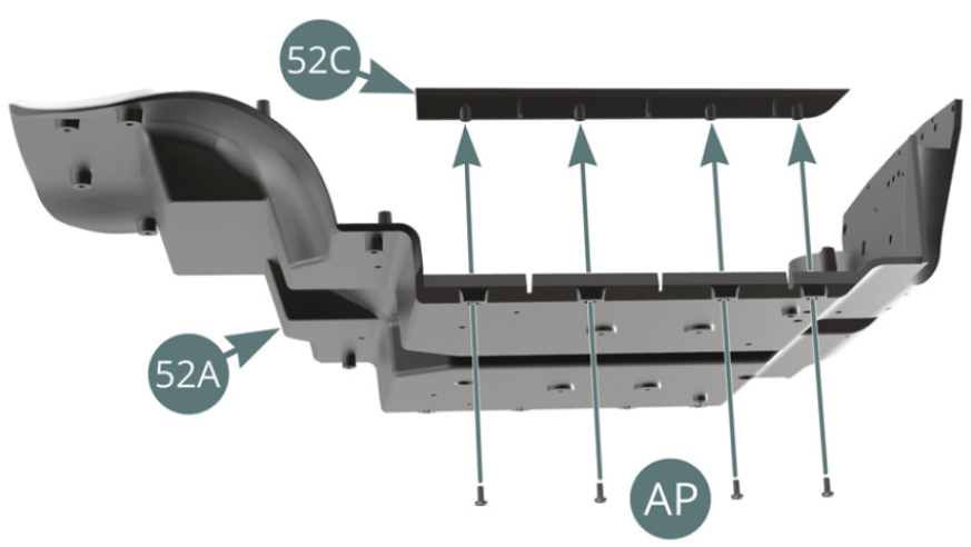
Position the left lateral edge (52B) on the cabin floor (52A) and secure – from below - with four AP screws. Position the right lateral edge (52C) on the cabin floor (52A) and secure – from below - with four AP screws.
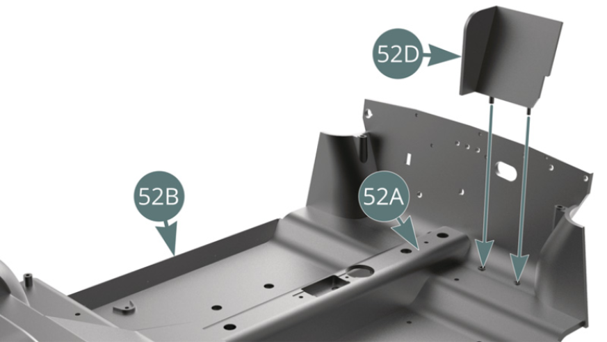
Step 2
Place the bulkhead (52D) on the cabin floor (52A) using the lugs provided for.
ASSEMBLY DIAGRAM
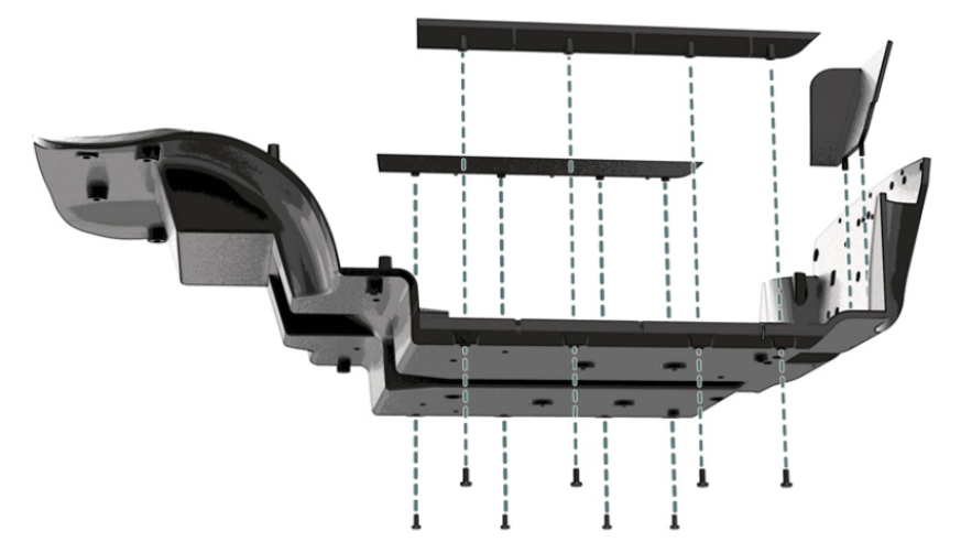
GENERAL VIEW