English
 français
 Deutsch
 español
 italiano
 português


Box 14
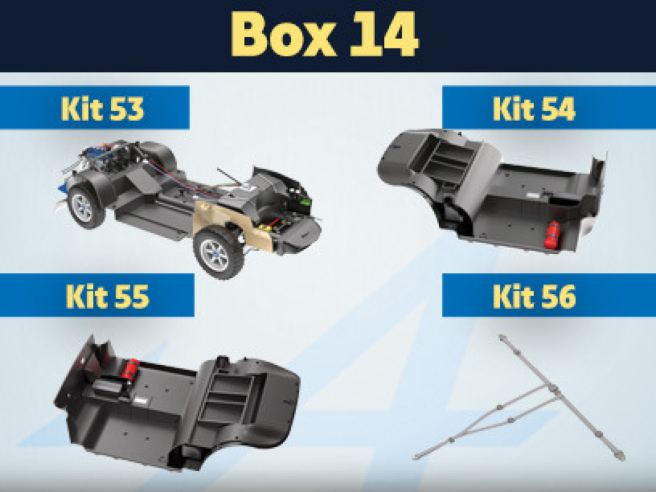
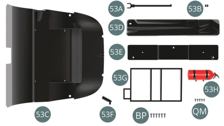
Kit 53 - Assembly of fuel tank and passenger compartment panels. Assembly of the steering column
Parts of kit
- 53A Steering column
- 53B Universal crossbar
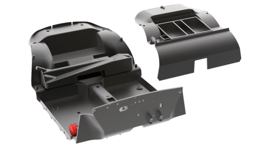
- 53C Rear passenger compartment panel
- 53D Fuel tank
- 53E Fuel tank bottom
- 53F Filler neck
- 53G Rear tray
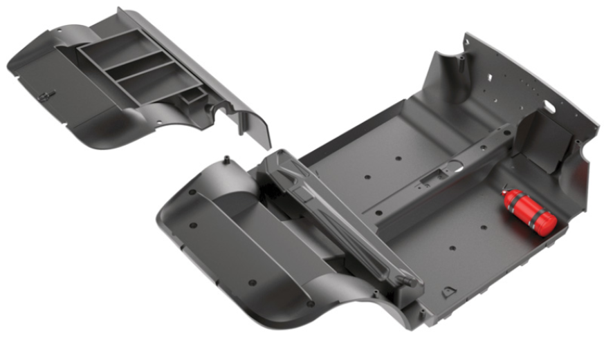
- 53H Fire extinguisher
- Screw BP M 1.7 x 5 mm (x 6)
- Screw QM M 1.4 x 3 mm (x 5)
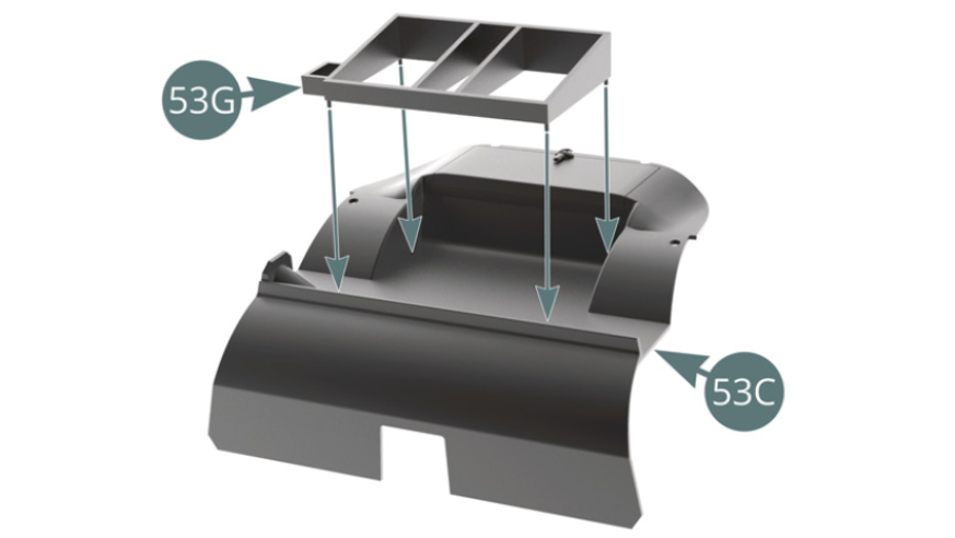
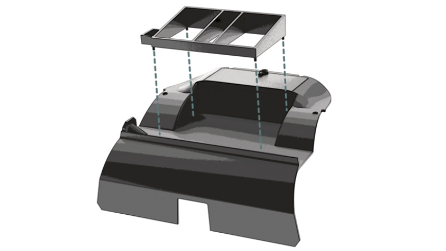
Step 1
Position the rear tray (53G) on the rear passenger compartment panel (53C).
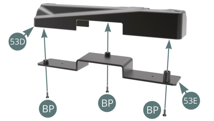
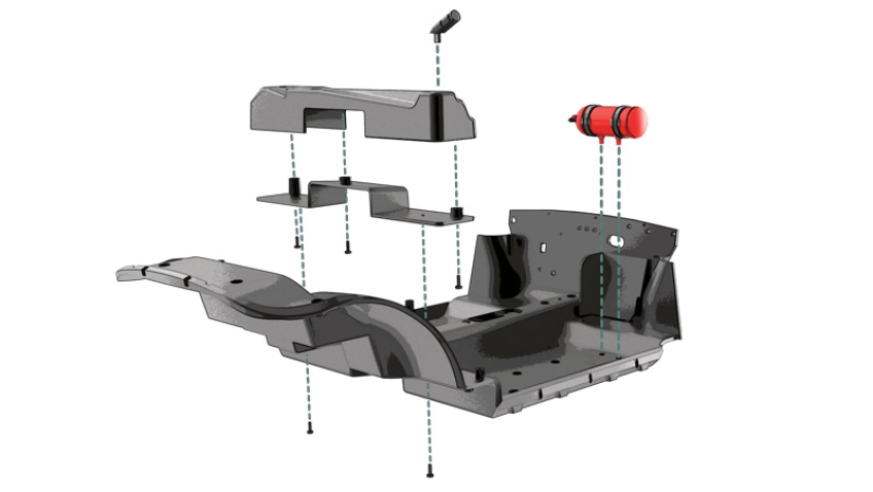
Place the tank base (53E) on the fuel tank (53D) and secure with three BP screws.
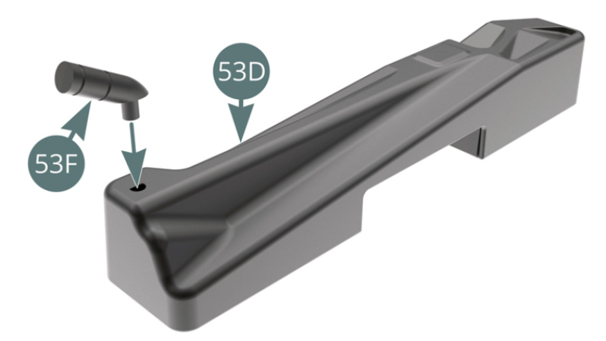
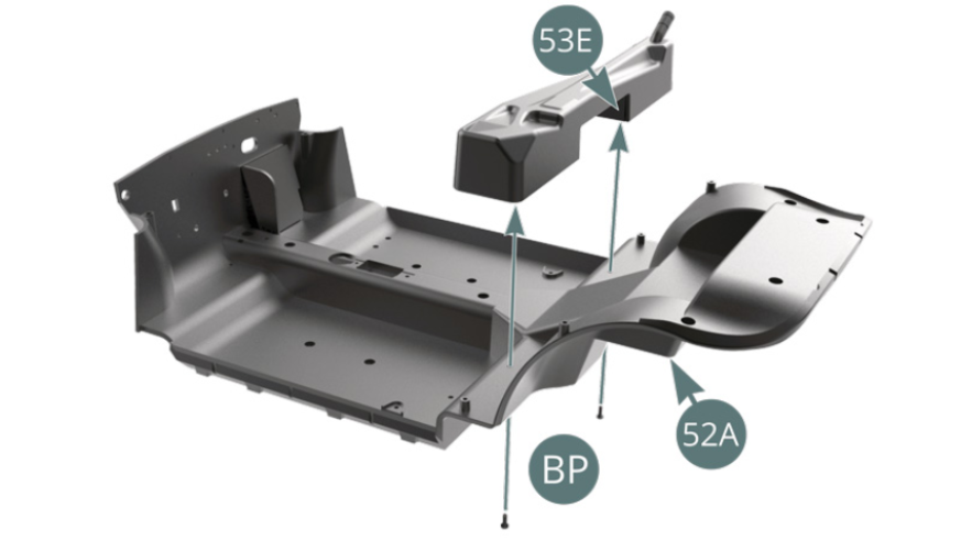
Step 2
Fit the filler neck (53F) onto the fuel tank (53D). Place the fuel tank (53D) with the attached tank bottom (53E) to the passenger compartment floor (52A) and secure it with two BP screws.
Step 3
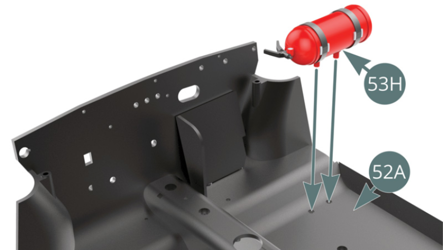
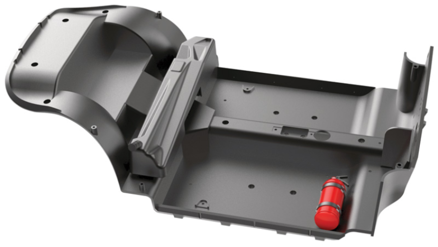
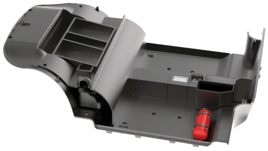
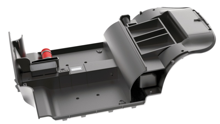
Position the fire extinguisher (53H) by using the two openings in the front right corner of the passenger compartment floor (52A) - see illustrations above.
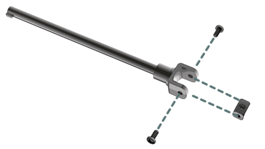
Step 4
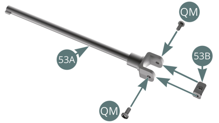
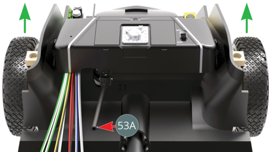
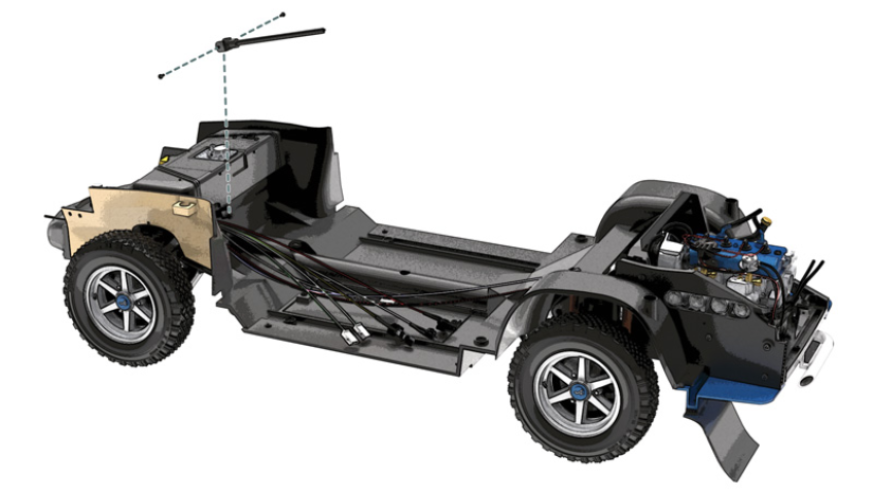
Position the universal crossbar (53B) on the fork of the steering column (53A) and secure it with two QM screws.
Step 5
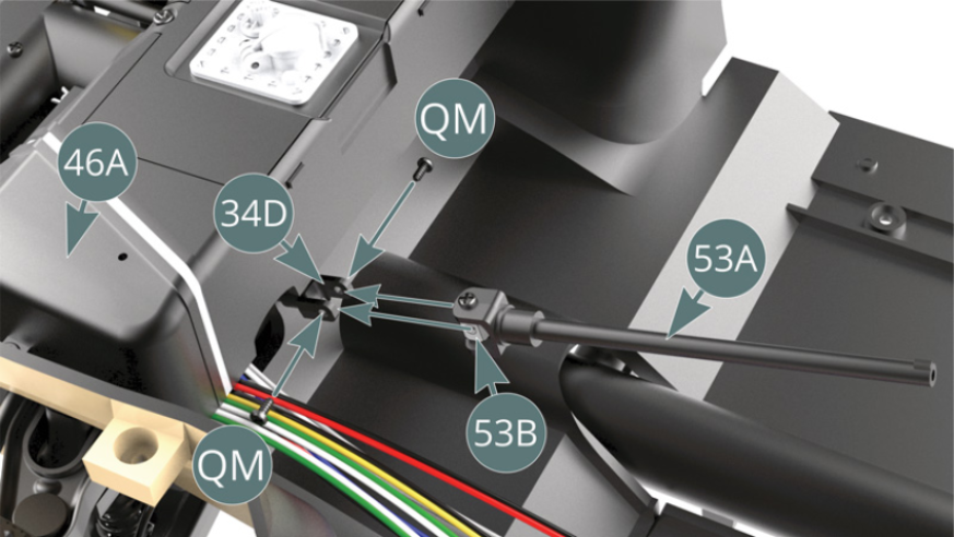
Read the following instructions carefully before starting assembly. Rotate the intermediate shaft (34D) so that its fork is placed on the universal crossbar (53B), then secure it with two QM screws. To facilitate access, the fuel tank (46A) - fitted in parts 48 step 4 - can be temporarily removed. Ensure that when the steering column (53A) is installed, the rack pin is pointing to the right and the wheels are pointing forwards (green arrows).
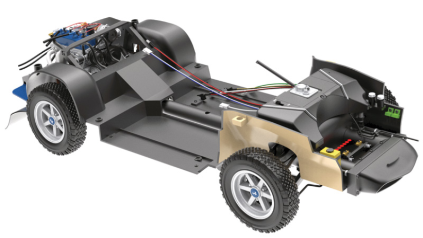
ASSEMBLY DIAGRAM
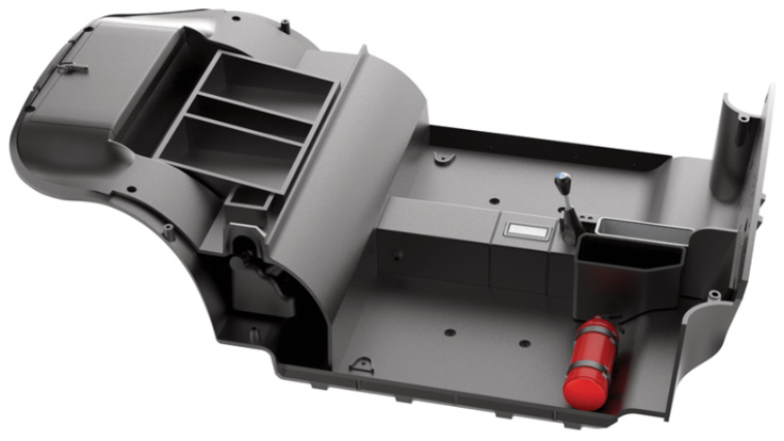
GENERAL VIEW
Kit 54 - Mounting of the centre console, assembly of accessories and map pockets
Parts of kit
- 54A Centre console
- 54B Map pocket
- 54C Map pocket
- 54D Ashtray frame
- 54E Ashtray cover
- 54F Ashtray
- 54G Reverse gear lock
- 54H Locking bracket
- Screw EP M 2.0 x 5 mm (x 3)
- Screw AP M 1.7 x 4 mm (x 3)
- Screw BP M 1.7 x 5 mm (x 8)

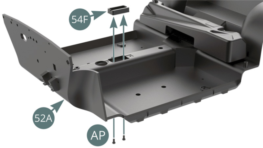
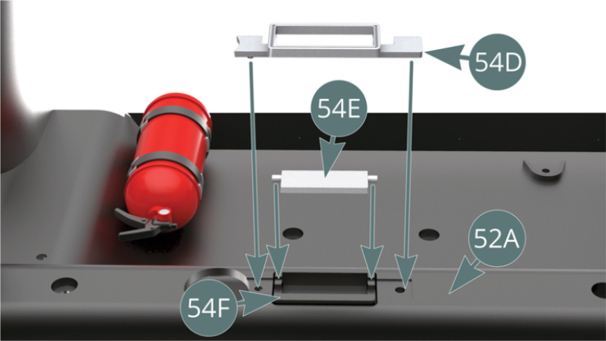
Step 1
Position the ashtray (54F) on the passenger compartment floor (52A) and secure it from below with two AP screws. Position the ashtray cover (54E) on the ashtray (54F) and then mount the ashtray frame (54D) on the passenger compartment floor (52A) and on the ashtray cover (54E).
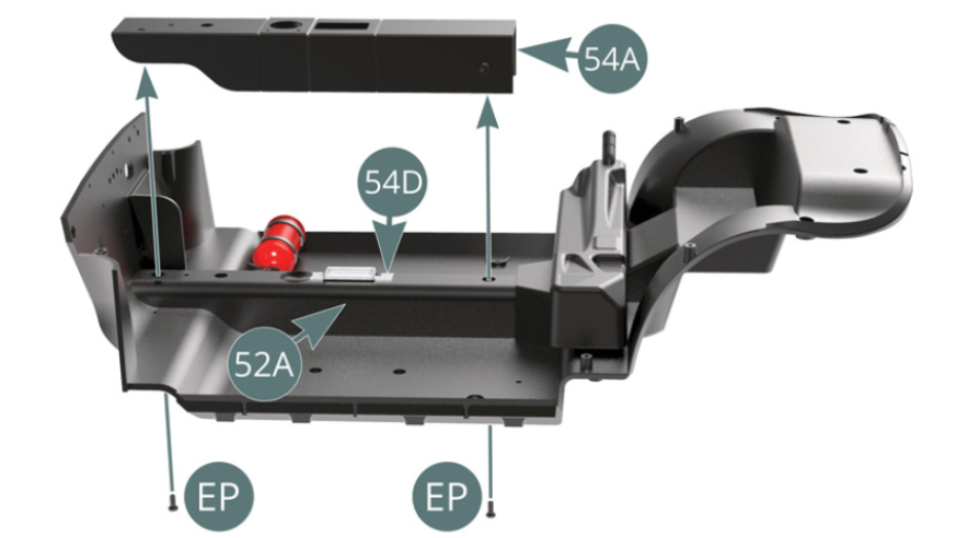
Step 2
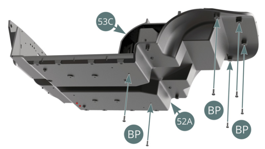
Position the centre console (54A) on the passenger compartment floor (52A) by embedding the ashtray frame (54D), then secure it from below using two EP screws. Place the rear passenger compartment panel (53C) on the passenger compartment floor (52A).
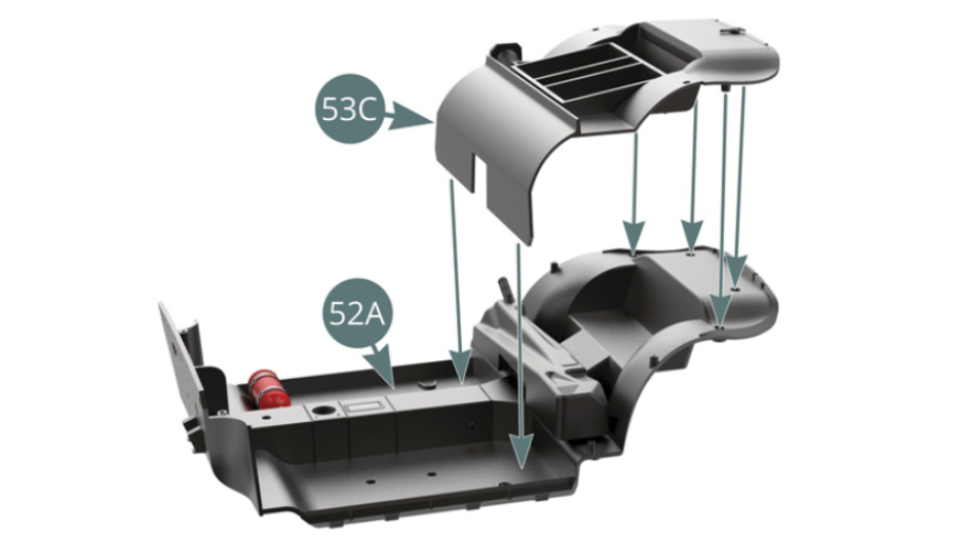
Step 3
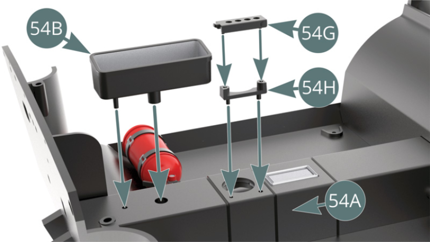
Secure the rear passenger compartment panel (53C) to the passenger compartment floor (52A) from below using six BP screws. Place the reverse gear lock (54G) and its locking bracket (54H) on the centre console (54A). Position the map pockets (54B) on the centre console (54A).
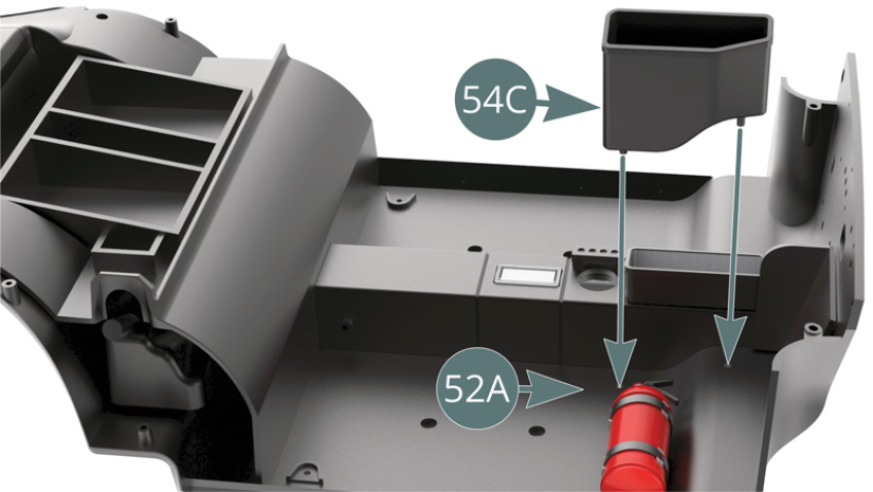
Step 4
Place map pockets (54C) on the centre console (54A).
ASSEMBLY DIAGRAM

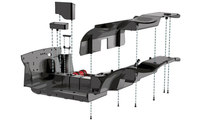
GENERAL VIEW
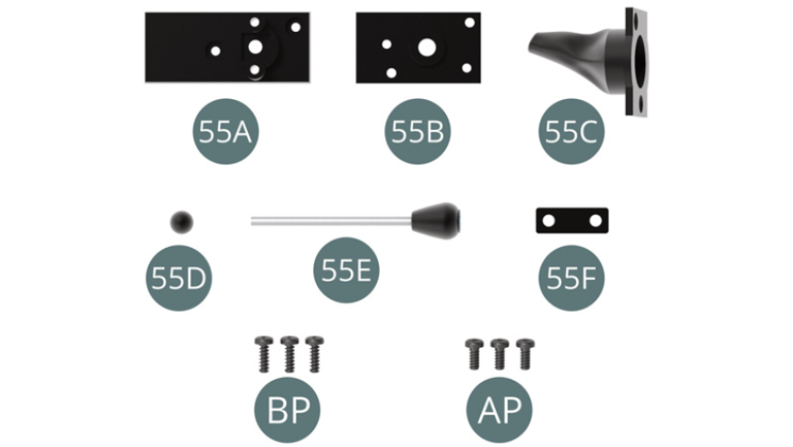
Kit 55 - Assembly and installation of the gear lever
Parts of kit
- 55A Bottom plate
- 55B Middle plate
- 55C Gear lever bellows
- 55D Ball joint
- 55E Gear lever
- 55F Bracket
- Screw BP M 1.7 x 5 mm (x 3)
- Screw AP M 1.7 x 4 mm (x 3)
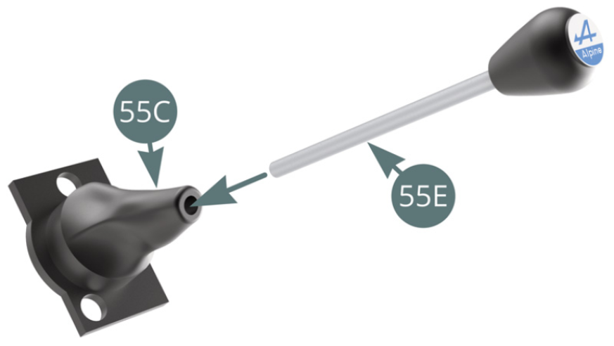
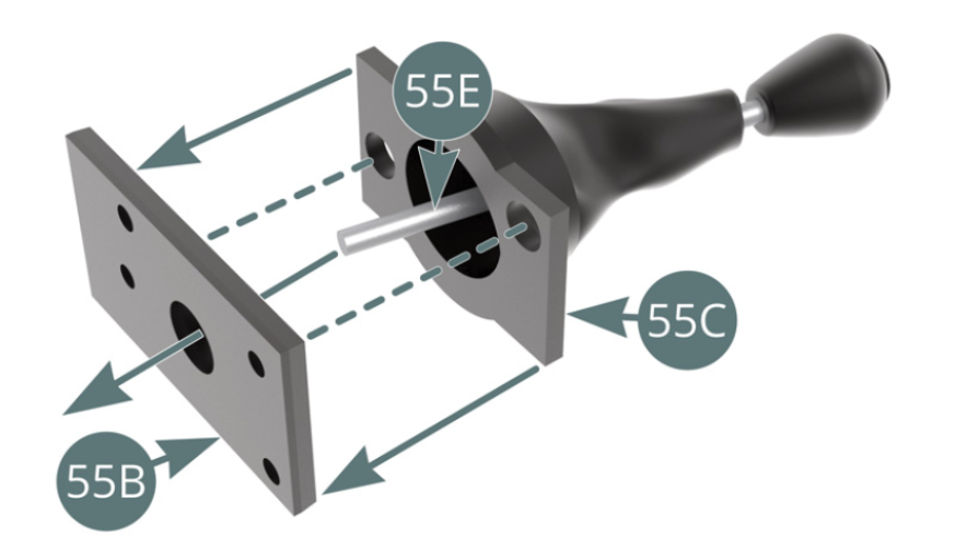
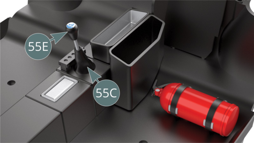
Step 1
Fit the gear lever (55E) into the bellows (55C). Place the bellows (55C) on the middle plate (55B), engaging the gear lever (55E ) in the central and widest opening.
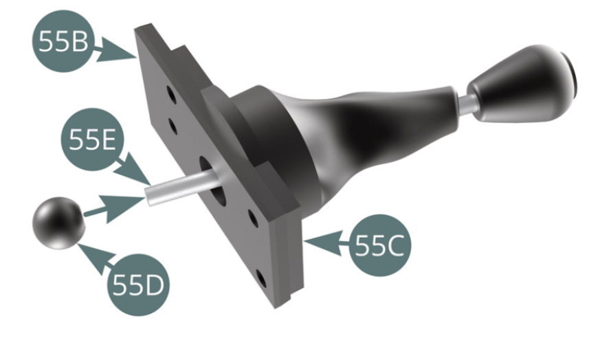
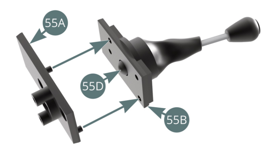
Step 2
Position the ball joint (55D) at the end of the gear lever (55E). Place the bottom plate (55A) on the middle plate (55B) using its two lugs.
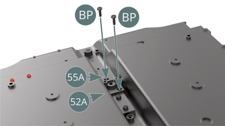
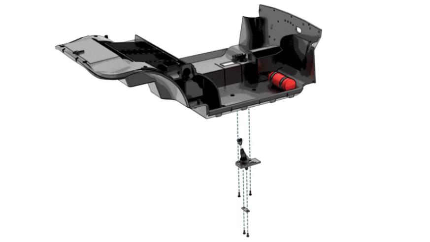
Step 3
Insert the gear lever (55 E) through the opening underneath the passenger compartment floor (52A), then position the bottom plate (55A) and secure with two BP screws (shown above).

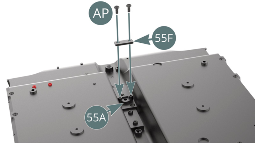
Step 4
Temporarily place the mounting bracket (55F) on the bottom plate (55A), securing it (but not too tightly) with two AP screws.
The gear lever (55E) and its bellows (55C) are positioned
ASSEMBLY DIAGRAM

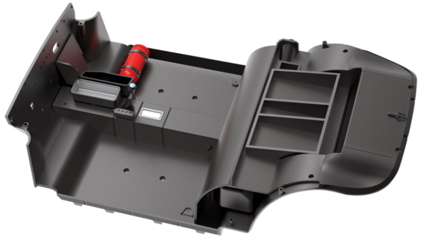
GENERAL VIEW
Kit 56 - Assembly of the driver's seatbelt
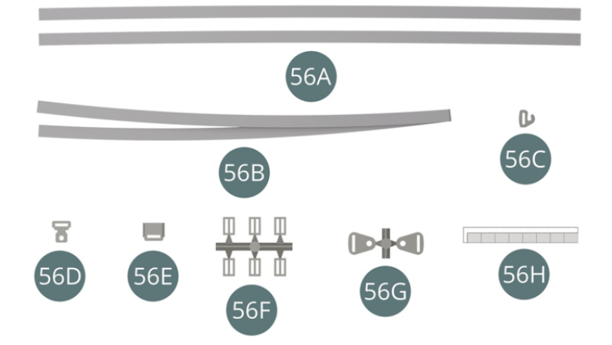
Parts of kit
- 56A Belt strap (x 2)
- 56B Seat belt
- 56C Hook buckle
- 56D Locking buckle
- 56E Locking buckle
- 56F Buckle (x 6)
- 56G Attachment plate (x 2)
- 56H Double-sided tape (x 8)
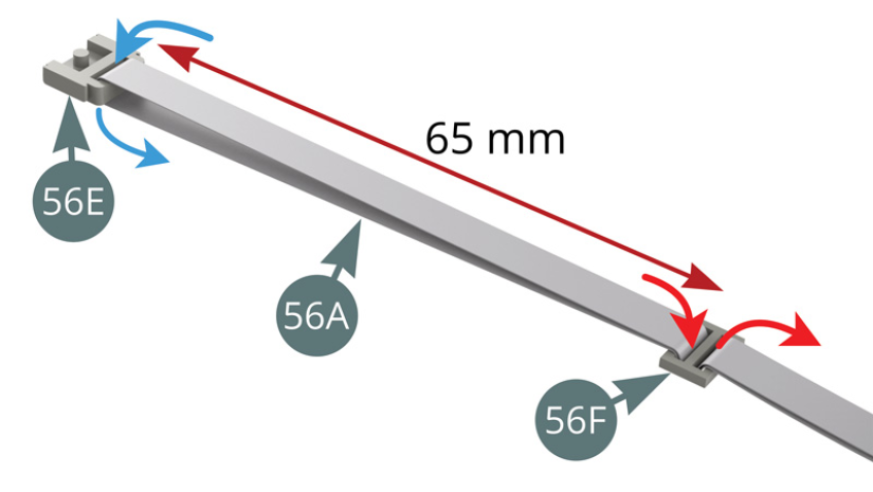
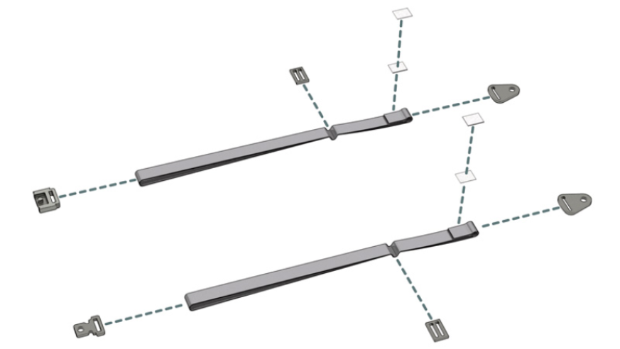
Step 1
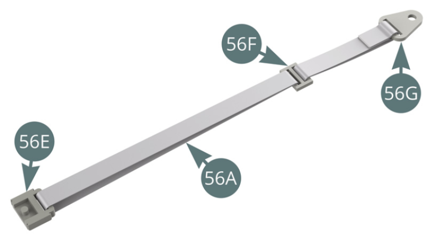
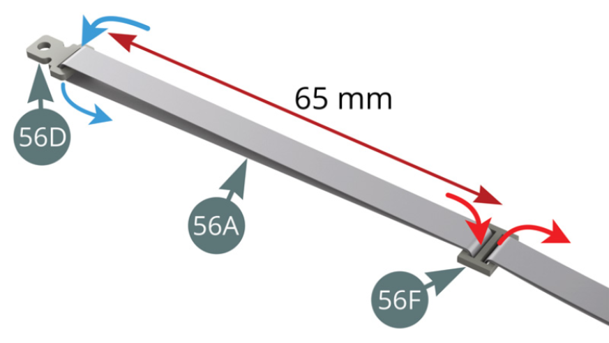
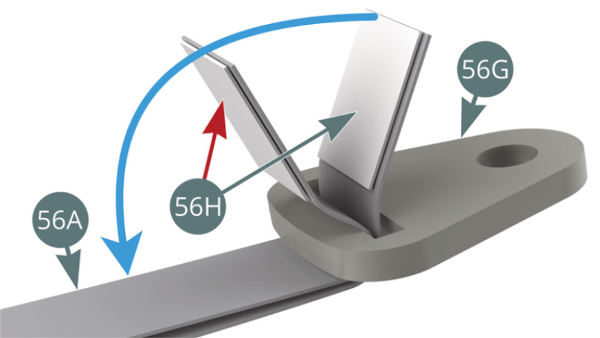
Pass the first belt strap (56A) through the locking buckle (56E), folding it gently in the middle (blue arrows). Join the two ends of the strap (56A) in a buckle (56F) - red arrows - so that it is 65 mm from the locking buckle (56E). Then pass the two parts of the belt strap (56A) together through an attachment plate (56G) - blue arrow, then secure the two ends of the strap with adhesives (56H) as shown below.
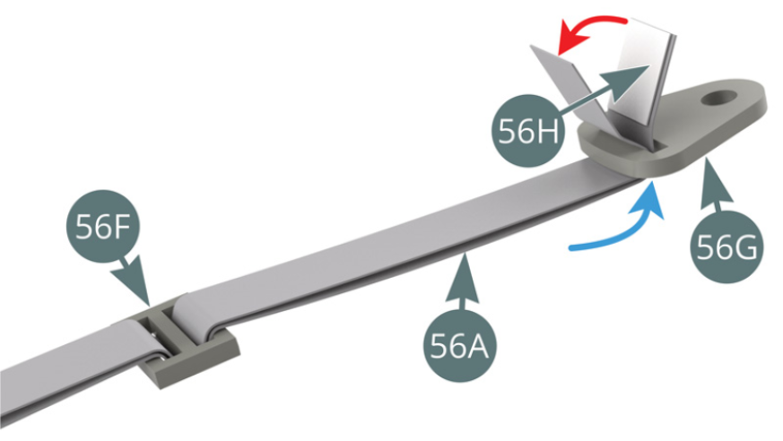
Step 2
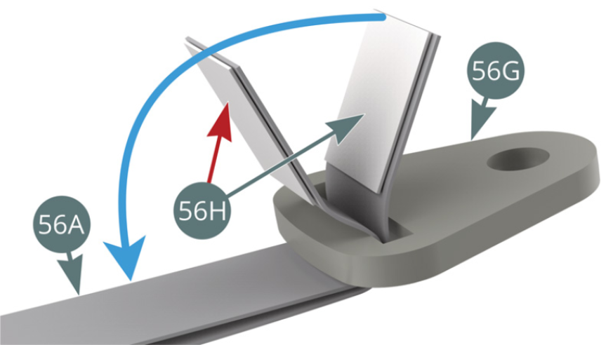
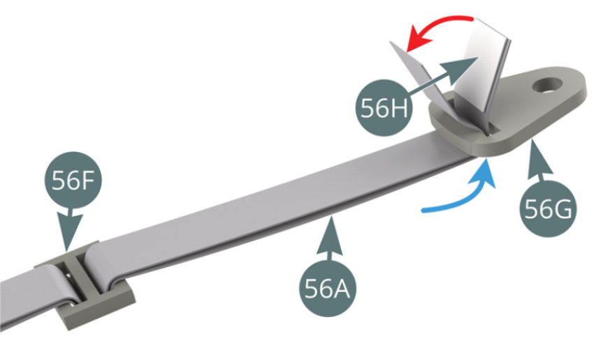
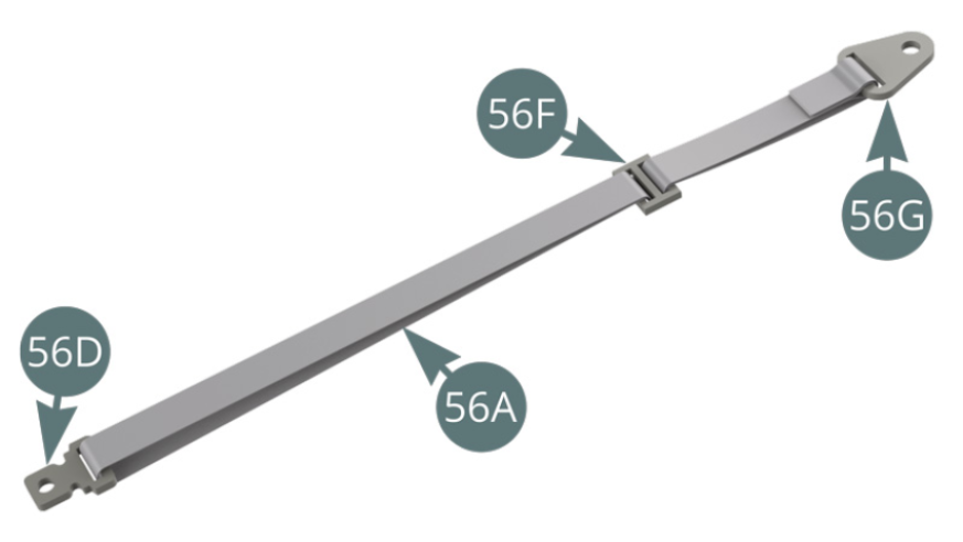
First apply double-sided adhesive (56H) below the end of the strap (56A) - red arrow -, then wind it around the attachment plate (56G) and fold it over to seal it. Then fold over the other end of the strap (56A) and use double-sided adhesive to stick it to the end already attached (blue arrow).
The left belt strap is now assembled.
Step 3
Pass the second belt strap (56A) through the locking buckle (56D), folding it gently in the middle (blue arrows). Pass the two ends of the strap (56A) together through a buckle (56F) - red arrows – so that it is 65 mm from the locking buckle (56D). Then pass the two parts of the belt strap (56A) together through an attachment plate (56G) - blue arrow -, then secure the two ends of the strap with adhesives (56H) as shown below.
Step 4
First apply double-sided adhesive (56H) below the end of the strap (56A) - red arrow -, then wind it around the attachment plate (56G) and fold it over to seal it. Then fold over the other end of the strap (56A) and use double-sided adhesive to the end already attached (blue arrow). The right belt strap is now assembled.

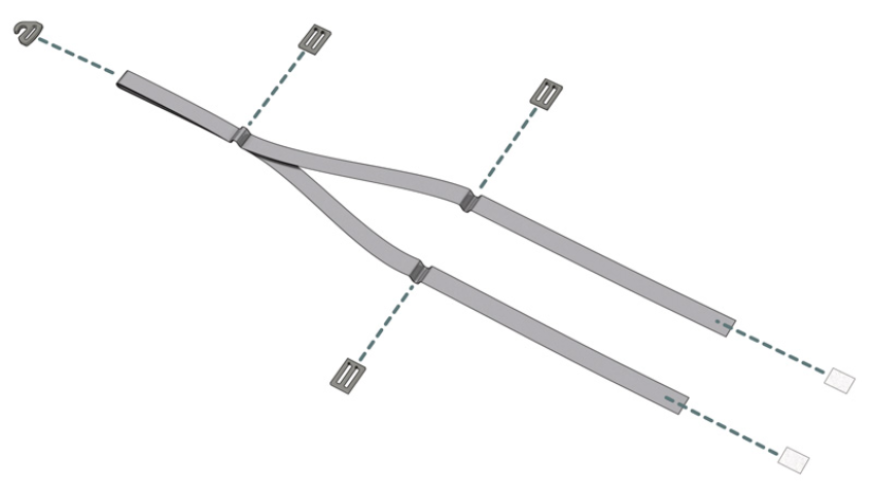
Step 5
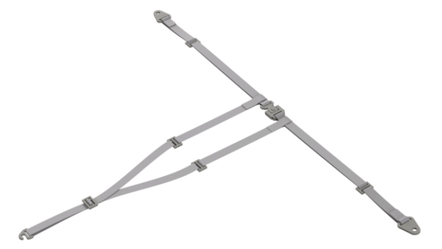
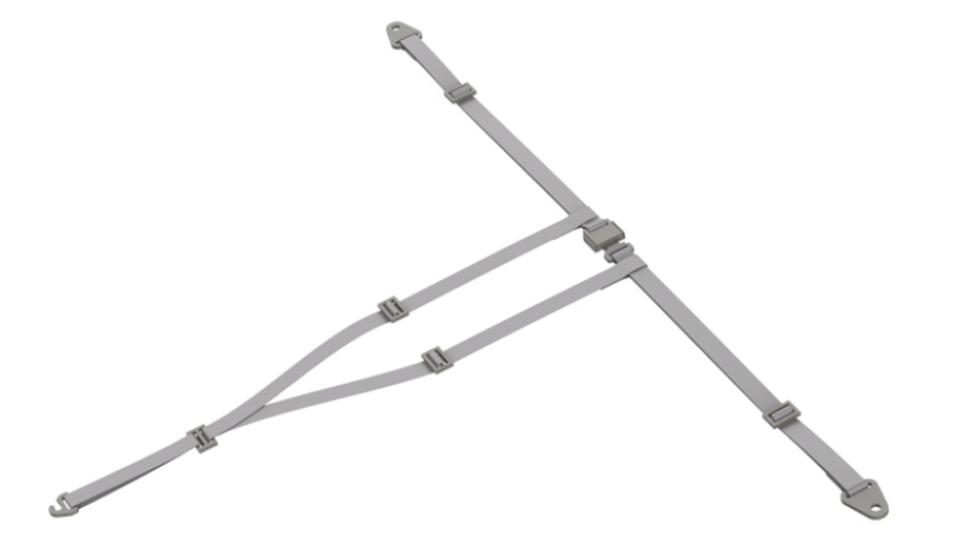
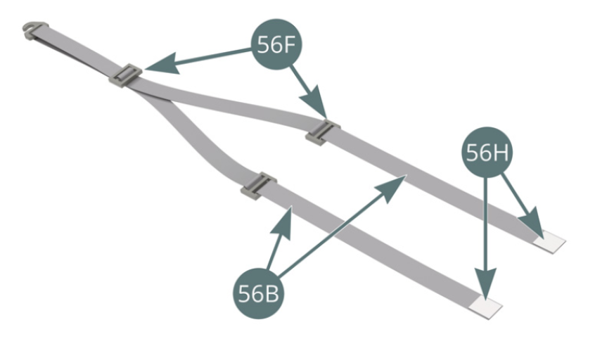
Pass the seatbelt (56B) through the hook buckle (56C), folding it gently in the middle (blue arrows). Bring the two ends of the seat belt (56B) together in a buckle (56F) (red arrows), keeping it 30 mm from the hook buckle (56C).
Then pass each of the two parts of the seat belt (56B) through a buckle (56F) (blue arrows), positioning them 55 mm from the previous buckle (56F).


Step 6

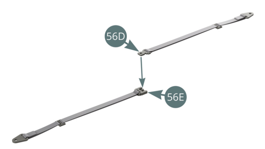
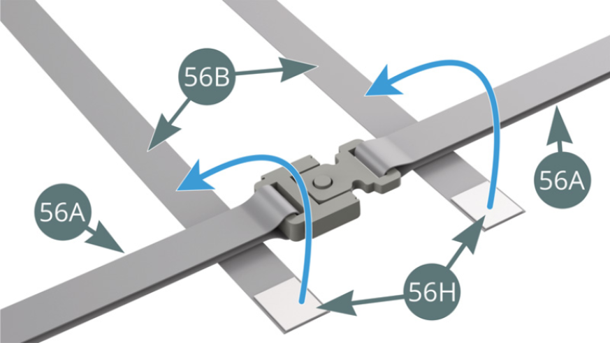
Place a double-sided adhesive tape (56H) on each end of the seat belt (56B). Place the locking buckle (56D) of the right belt strap on the locking buckle (56E) of the left belt strap.

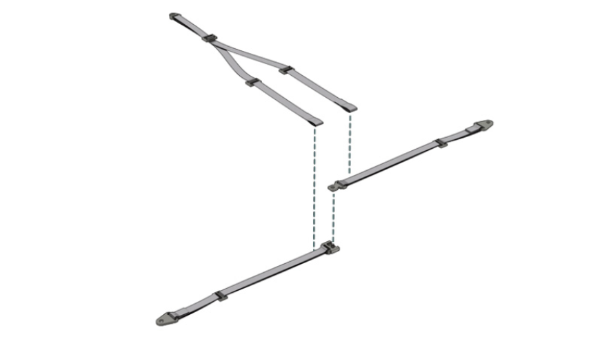
Step 7
Bring the right and left belt straps (56A) (connected by their locking buckles) over the ends of the seat belts (56B). Fold the ends of the seat belts (56B) over the right and left belt straps (56A) and secure them with the double-sided adhesives that are already present (blue arrows).
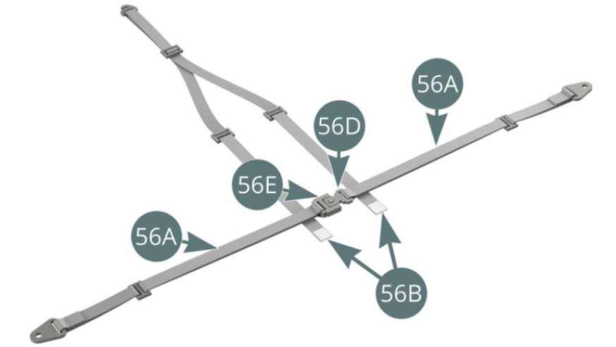
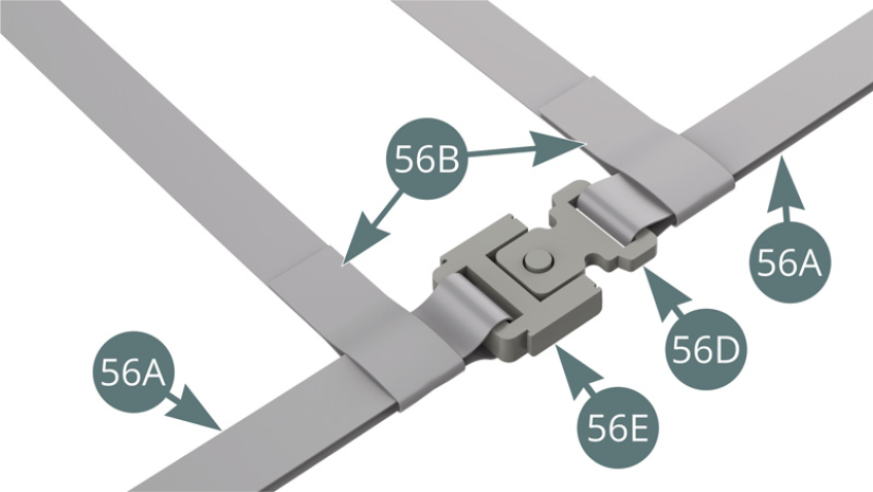
Step 8

The seat belts (56B) are attached to the right and left belt straps (56A).

ASSEMBLY DIAGRAM
GENERAL VIEW