English
 français
 Deutsch
 español
 italiano
 português


Box 15
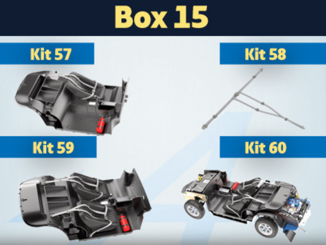
Kit 57 - Assembly and installation of the driver's seat. Installation of electrical cables
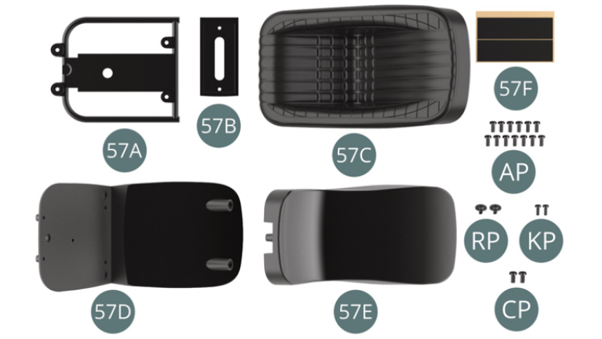
Parts of kit
- 57A Seat frame
- 57B Seat base
- 57C Seat upholstery
- 57D External panel
- 57E Internal panel
- 57F Adhesive tape (x 2)
- Screw AP M 1.7 x 4 mm (x 13)
- Screw RP M 1.7 x 3 x 5.5 mm (x 2)
- Screw KP M 1.4 x 4 mm (x 2)
- Screw CP M 2.0 x 4 mm (x 2)
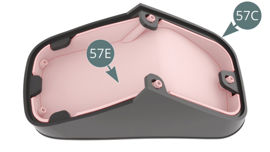
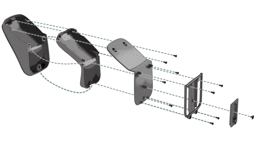
Step 1
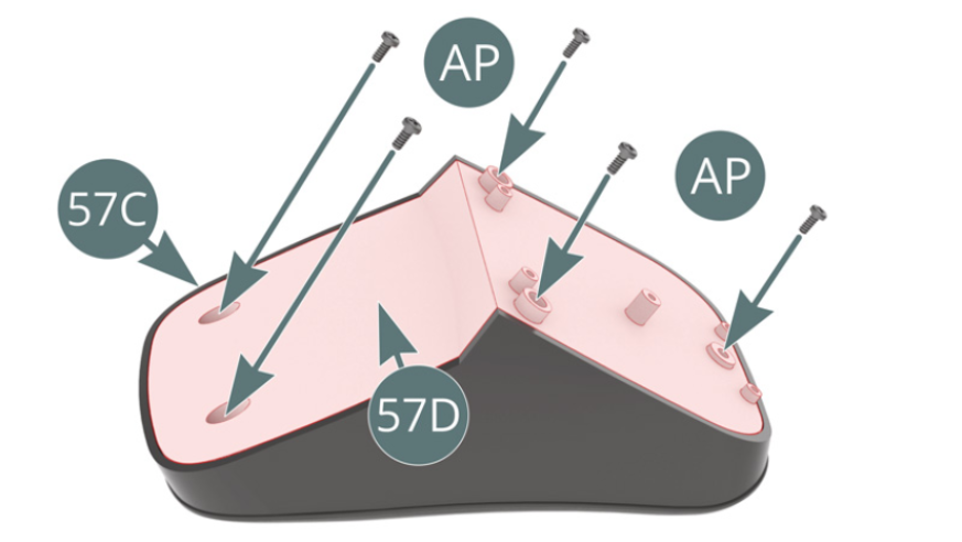
Place the seat upholstery (57C) on the internal panel (57E). Place the external panel (57D) on the seat upholstery (57C) and secure it with five AP screws.
Step 2
Position the seat frame (57A) on the external panel (57D) and secure with four AP screws. Position the seat base (57B) on the external panel (57D) and secure with an RP screw, ensuring that the base slides correctly.


Step 3
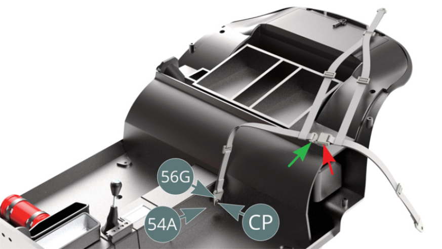
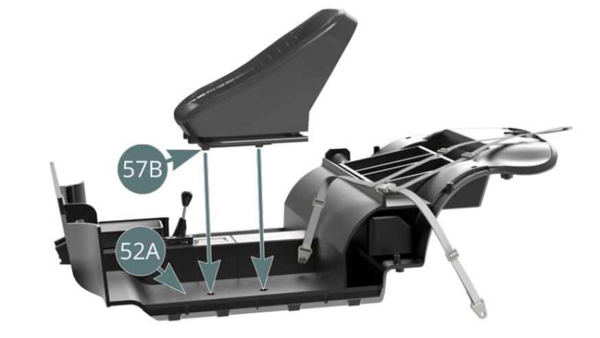
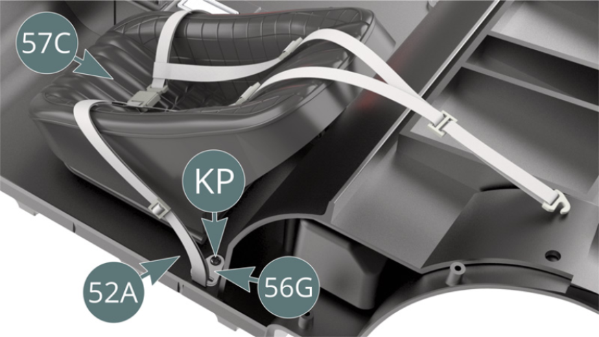
Place the driver's seat belt attachment plate (56G) on the centre console (54A) and secure with a CP screw. Verify that the locking buckles are correctly positioned as indicated by the green and red arrows. Align the seat base brackets (57B) with the seat housing located in the cabin floor (52A) and secure from below with two AP screws as shown in the illustration opposite.
Step 4
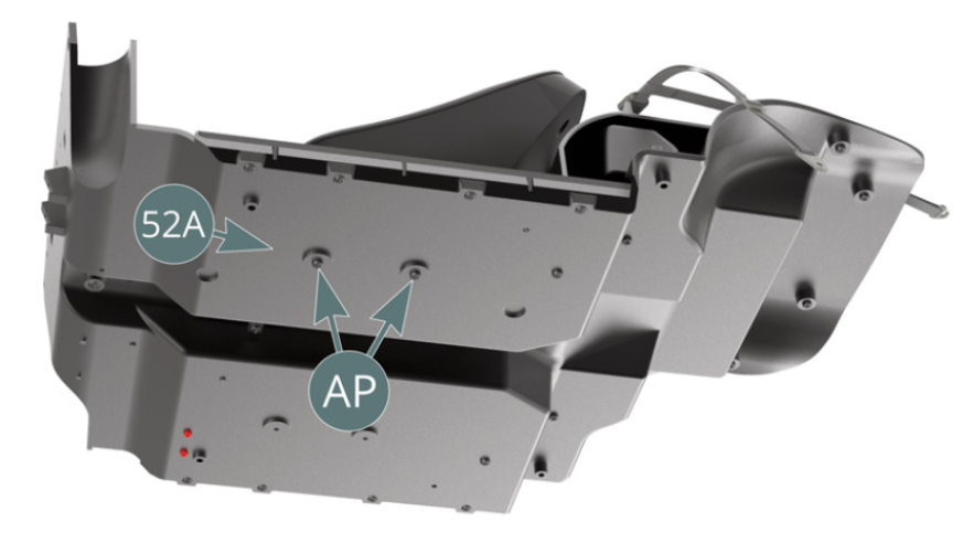
The driver's seat is now fixed to the cabin floor (52A) with two AP screws. Place the seat belt above the seat upholstery (57C) and secure the attachment plate (56G) of the left strap to the cabin floor (52A) with a KP screw.
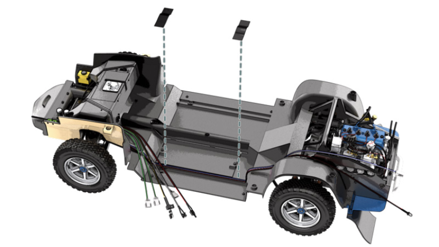
Step 5
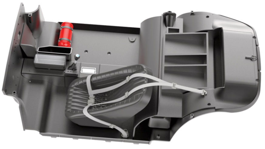
The driver's seat and its belt are fixed to the cabin floor.
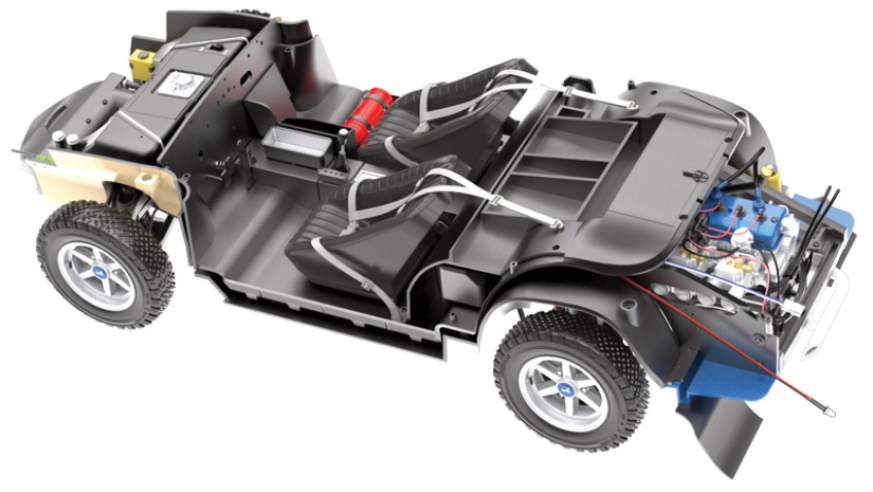
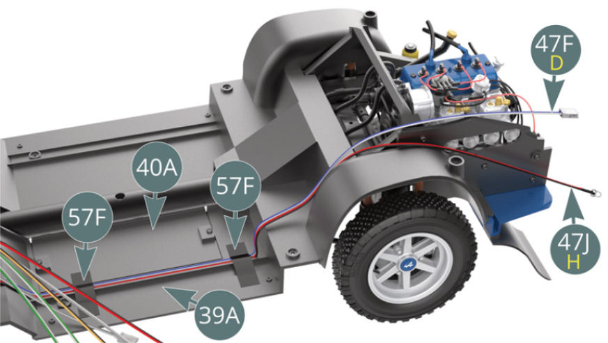
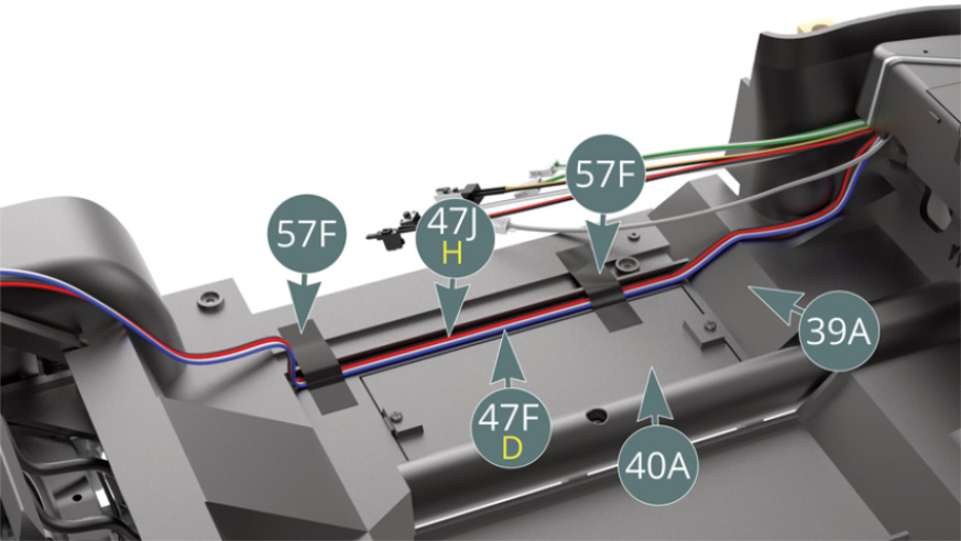
Guide the LED cable H / red – black (47J) and the cable D / blue – white (47F) along the edge of the chassis floor (39A) and the floor panel (40A), then secure them with two adhesive tapes (57F).
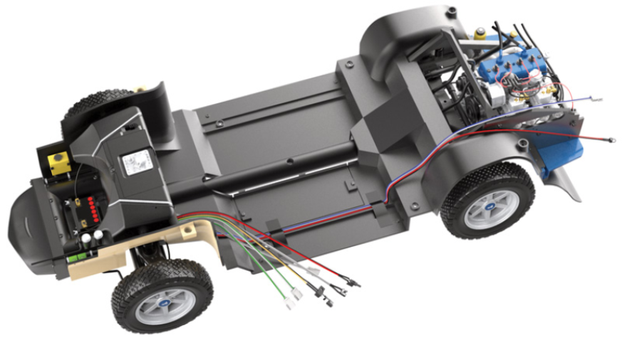
Step 6
The LED H cable (47J) and D cable (47F) are attached to the chassis floor (39A) and floor panel (40A) with two adhesive tapes (57F).
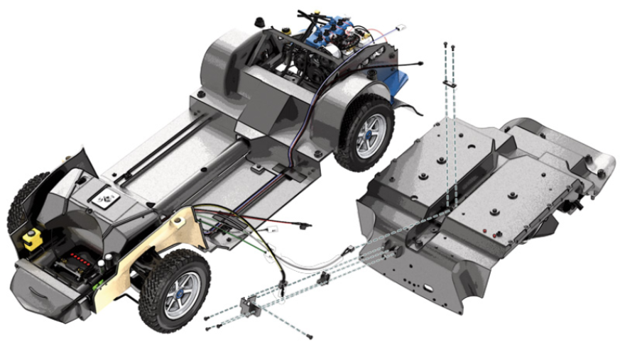
ASSEMBLY DIAGRAM

GENERAL VIEW
Kit 58 - Assembly of the passenger’s seat belt
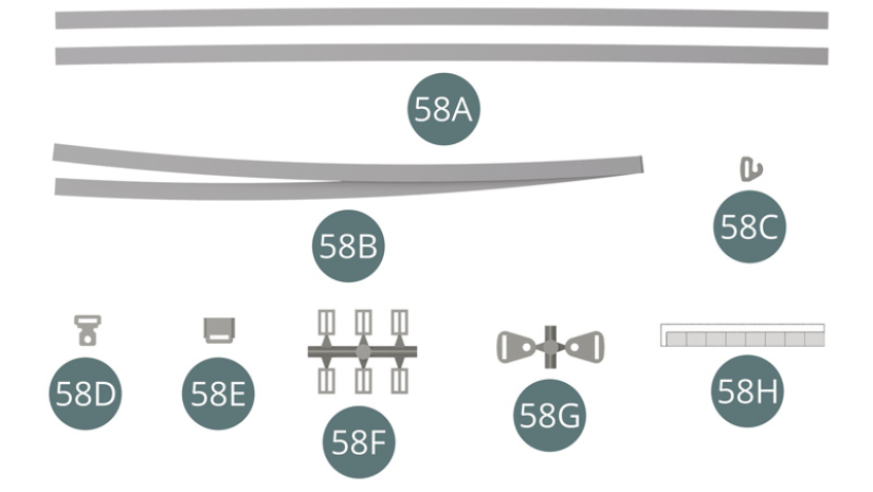
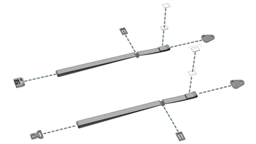
Parts of kit
- 58A Belt strap (x 2)
- 58B Safety belt
- 58C Hook buckle
- 58D Locking buckle
- 58E Locking buckle
- 58F Buckle (x 6)
- 58G Attachment plate (x 2)
- 58H Double-sided tape (x 8)
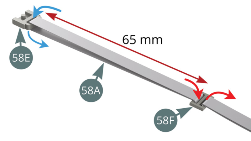
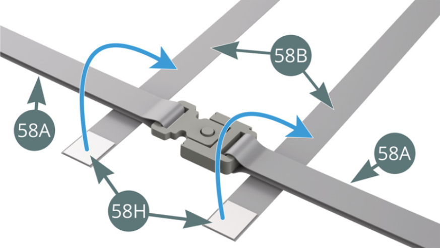
Step 1
Pass the first belt strap (58A) through the locking buckle (58E), folding it gently in the middle (blue arrows). Join the two ends of the strap (58A) in a buckle (58F) - red arrows - so that it is 65 mm from the locking buckle (58E). Then pass the two parts of the belt strap (58A) together through an attachment plate (58G) - blue arrow, then secure the two ends of the strap with adhesives (58H) as shown above.
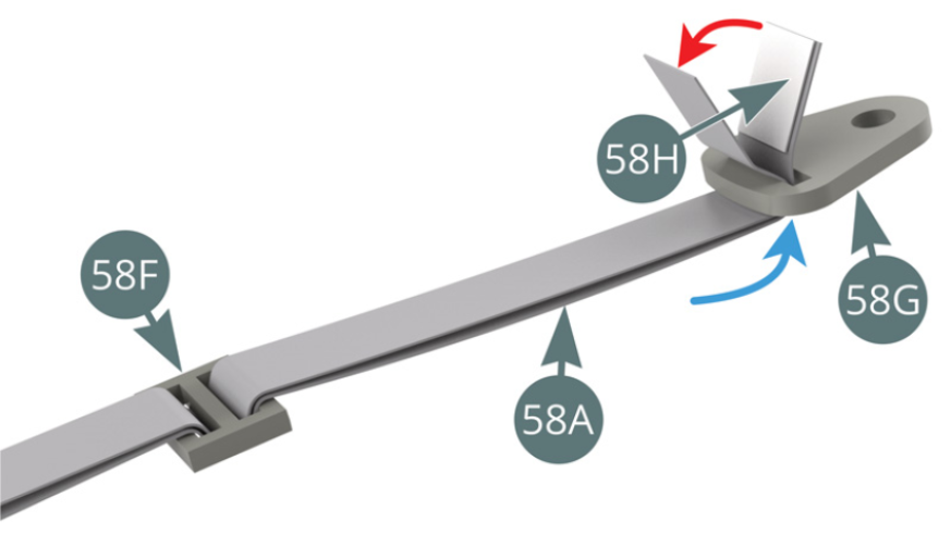
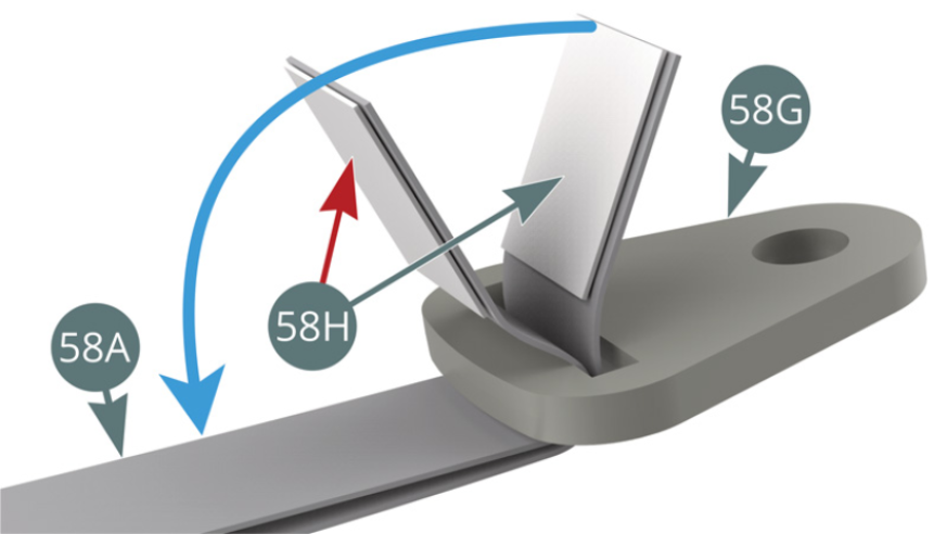
Step 2
First apply double-sided adhesive (58H) below the end of the strap (58A) - red arrow -, then wind it around the attachment plate (58G) and fold it over to seal it. Then fold over the other end of the strap (58A) and use double-sided adhesive to stick it to the end already attached (blue arrow).
The right belt strap is now assembled.

Step 3
Pass the second belt strap (58A) through the locking buckle (58D), folding it gently in the middle (blue arrows). Pass the two ends of the strap (58A) together through a buckle (58F) - red arrows – so that it is 65 mm from the locking buckle (58D).
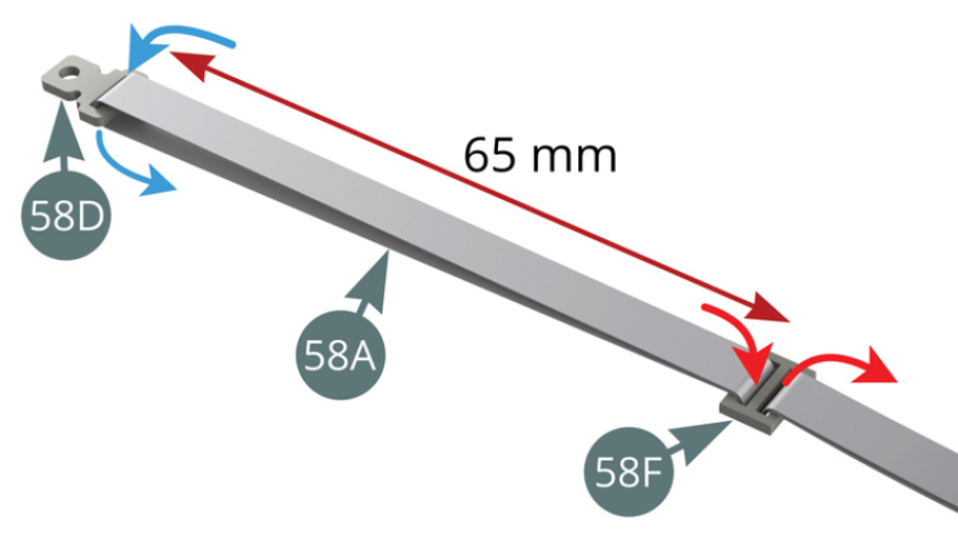
Then pass the two parts of the belt strap (58A) together through an attachment plate (58G) - blue arrow -, then secure the two ends of the strap with adhesives (58H) as shown below.
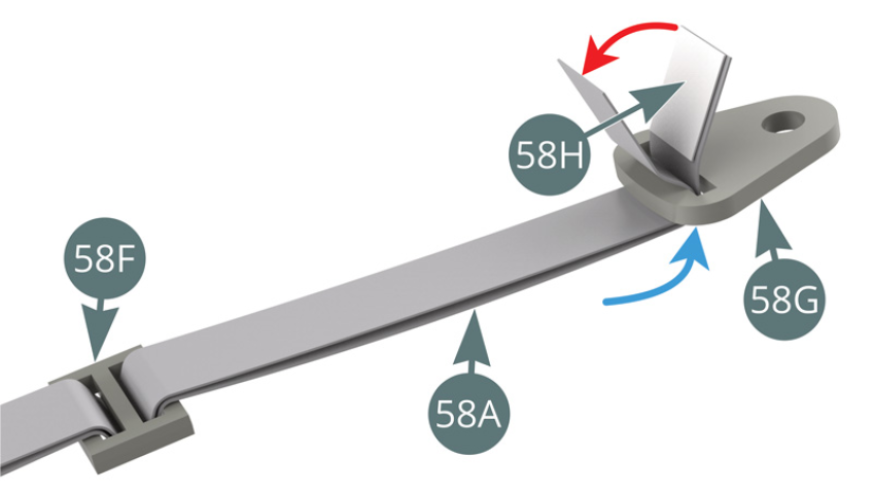
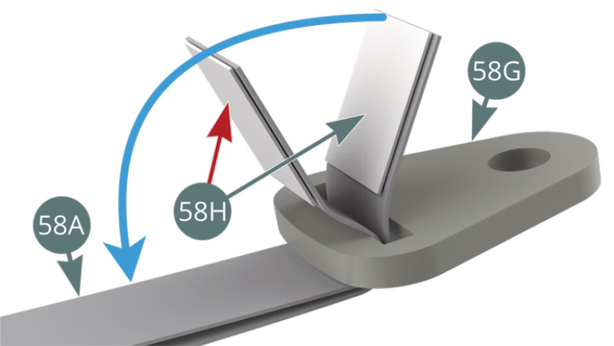
Step 4
First apply double-sided adhesive (58H) below the end of the strap (58A) - red arrow -, then wind it around the attachment plate (58G) and fold it over to seal it. Then fold over the other end of the strap (58A) and use double-sided adhesive to the end already attached (blue arrow).
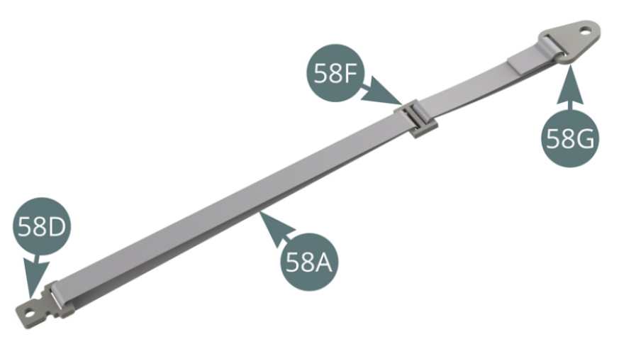
The left belt strap is now assembled.
Step 5
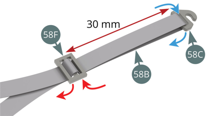
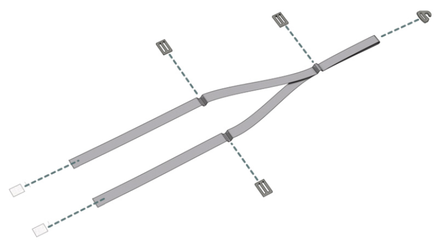
Pass the seatbelt (58B) through the hook buckle (58C), folding it gently in the middle (blue arrows). Bring the two ends of the seat belt (58B) together in a buckle (58F) (red arrows), keeping it 30 mm from the hook buckle (58C).
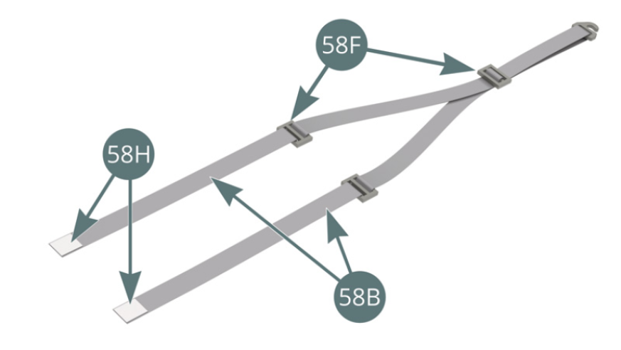
Then pass each of the two parts of the seat belt (58B) through a buckle (58F) (blue arrows), positioning them 55 mm from the previous buckle (58F).

Step 6
Place a double-sided adhesive tape (58H) on each end of the seat belt (58B).
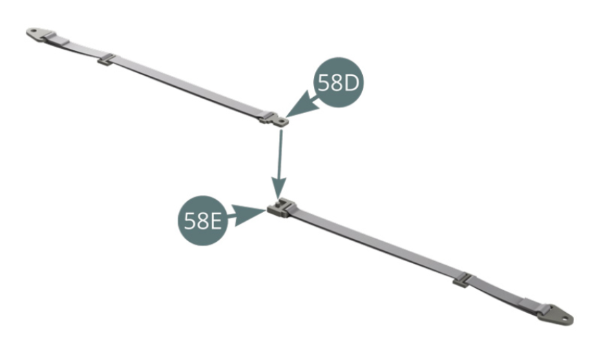
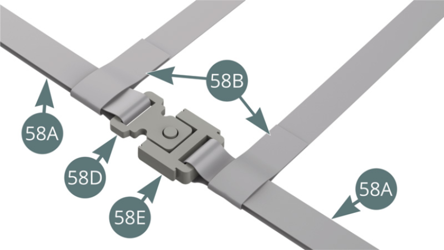
Place the locking buckle (58D) of the left belt strap on the locking buckle (58E) of the right belt strap.
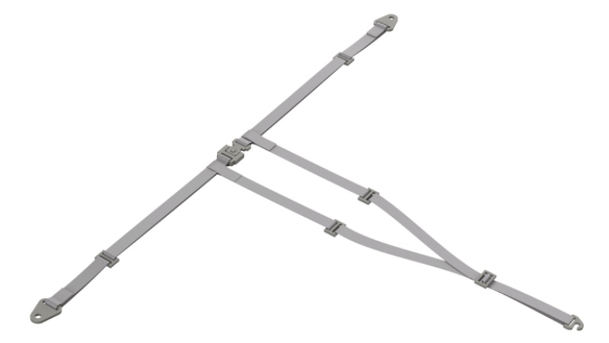
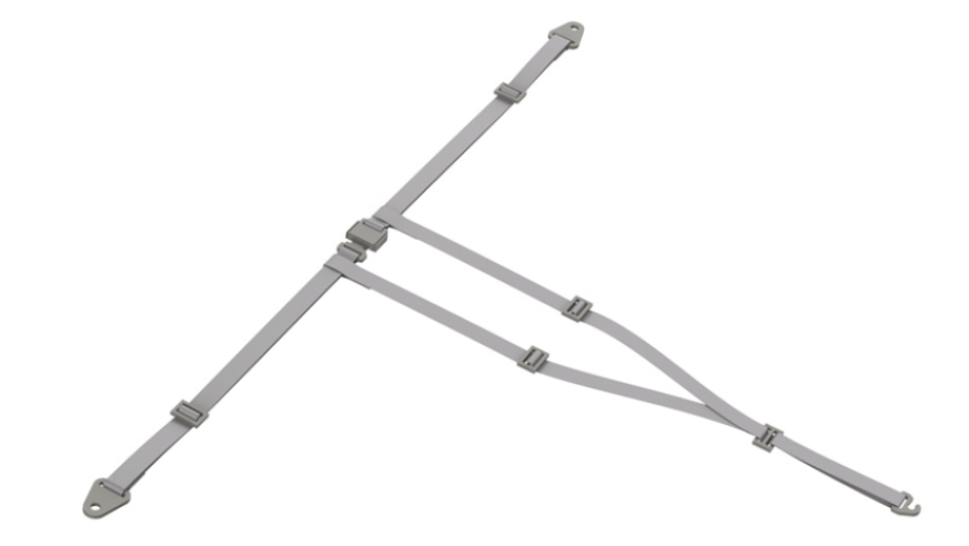
Step 7
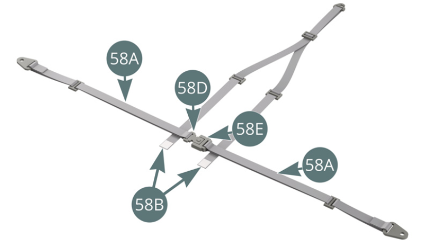
Bring the right and left belt straps (58A) (connected by their locking buckles) over the ends of the seat belts (58B).
Step 8
Fold the ends of the seat belts (56B) over the right and left belt straps (56A) and secure them with the double-sided adhesives that are already present (blue arrows).
Step 9
The seat belts (58B) are attached to the right and left belt straps (58A).
ASSEMBLY DIAGRAM

GENERAL VIEW
Kit 59 - Assembly and installation of the passenger’s seat
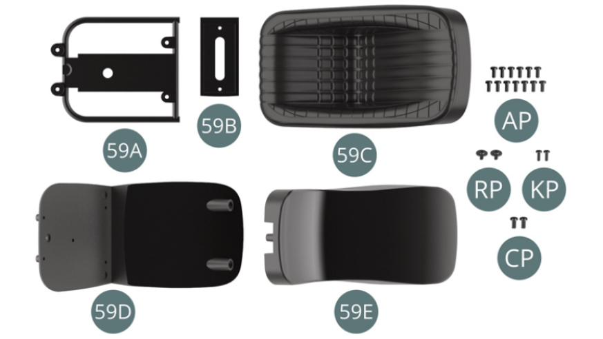
Parts of kit
- 59A Seat frame
- 59B Seat base
- 59C Seat upholstery
- 59D Exterior panel
- 59E Interior panel
- Screw AP M 1.7 x 4 mm (x 13)
- Screw RP M 1.7 x 3 x 5.5 mm (x 2)
- Screw KP M 1.4 x 4 mm (x 2)
- Screw CP M 2.0 x 4 mm (x 2)
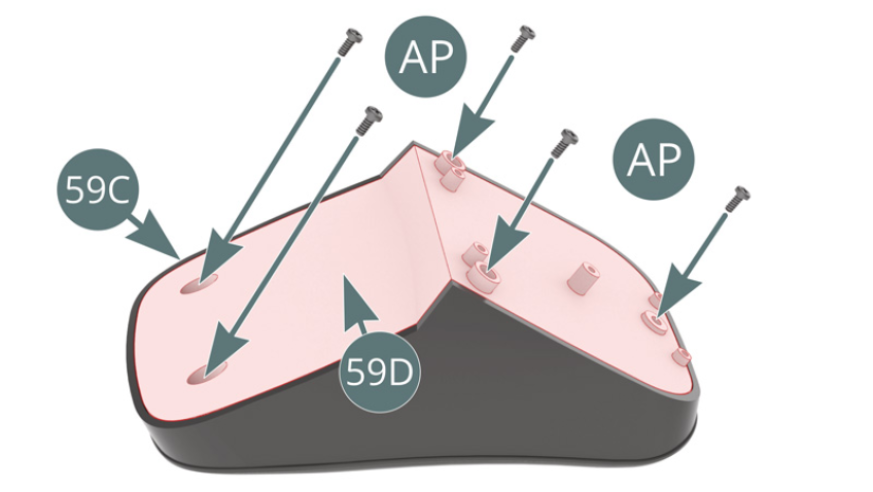
Step 1
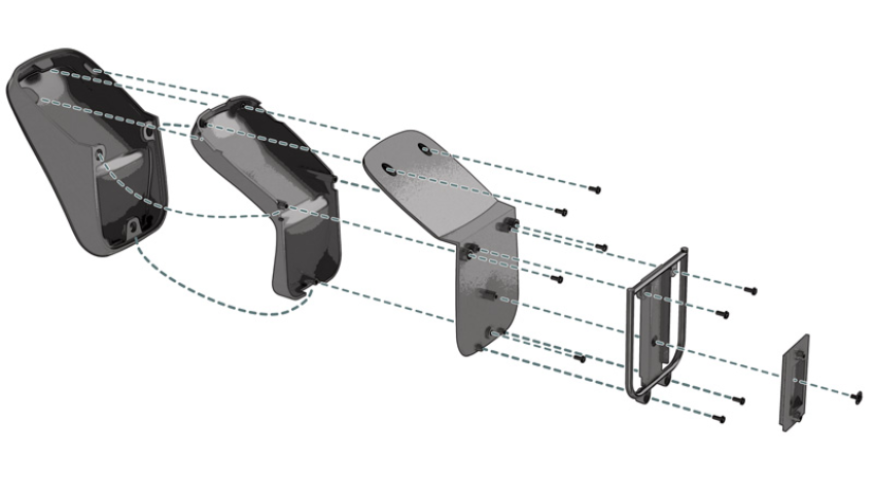
Place the seat upholstery (59C) on the interior panel (59E). Place the exterior panel (59D) on the seat upholstery (59C) and secure with five AP screws.

Step 2
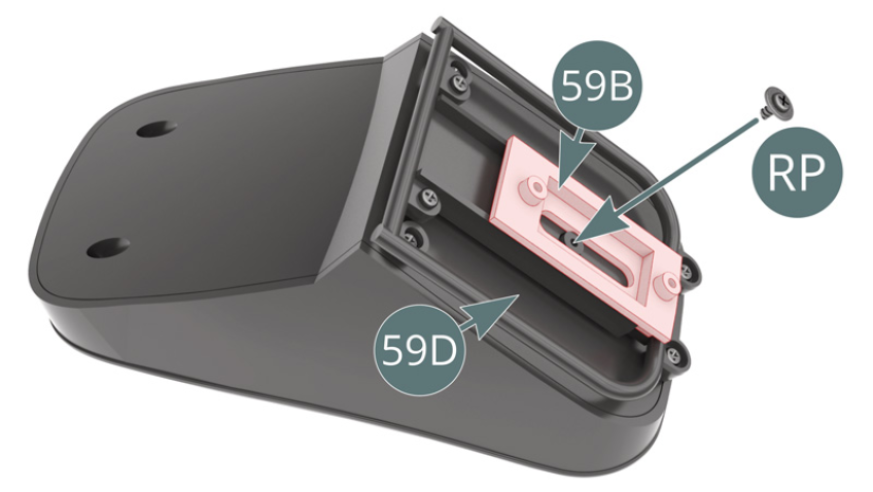
Place the seat frame (59A) on the external panel (59D) and secure with four AP screws. Position the seat base (59B) onto the external panel (59D) and secure it with an RP screw, ensuring that the base slides correctly.

Step 3
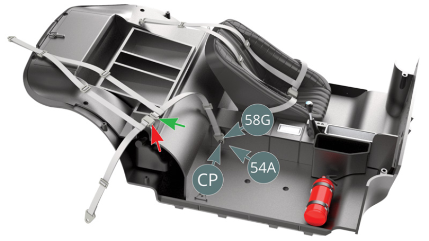
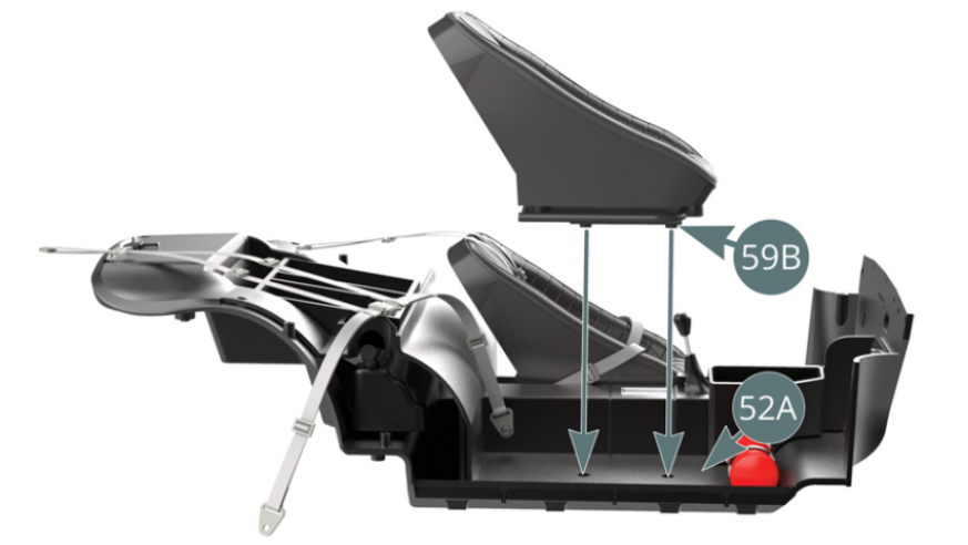
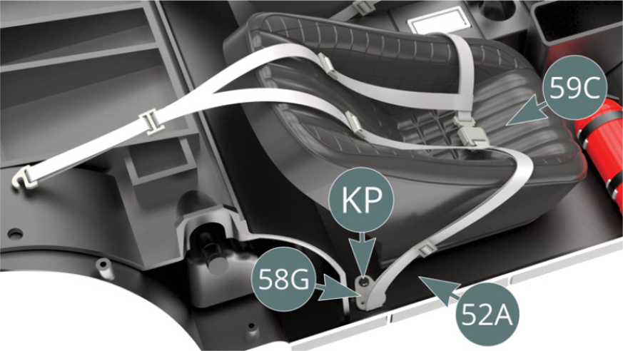
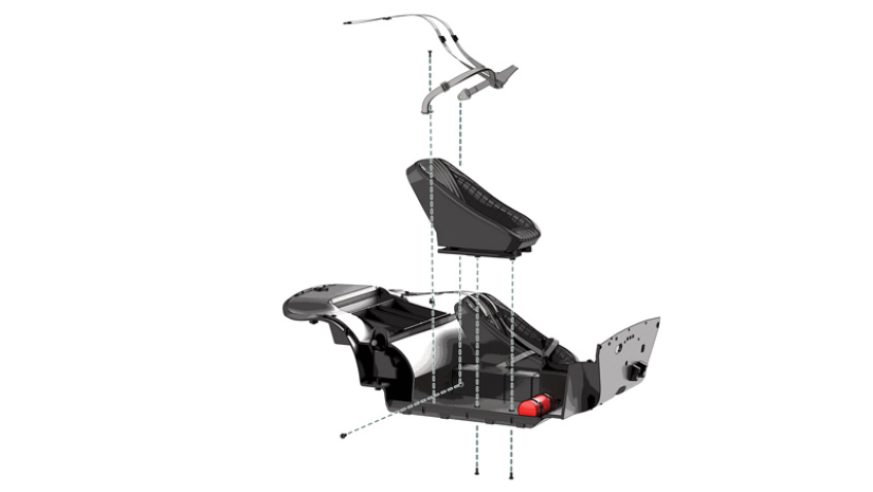
Place the attachment plate (58G) of the passenger's seat belt on the center console (54A) and secure with a CP screw. Check that the locking buckles are correctly positioned as indicated by the green and red arrows. Align the seat base brackets (59B) with the seats housings located in the cabin floor (52A) and secure them from below with two AP screws as shown.
Step 4
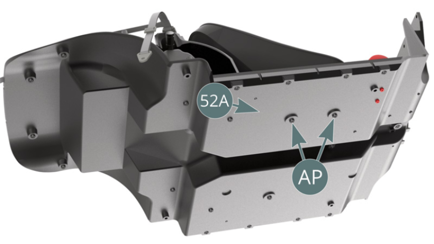
The passenger’s seat is fixed to the cabin floor (52A) with two AP screws. Place the seat belt above the seat upholstery (59C) and secure the attachment plate (58G) of the right strap to the cabin floor (52A) with a KP screw.
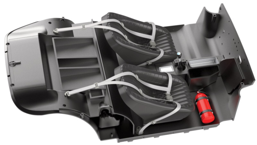
ASSEMBLY DIAGRAM
GENERAL VIEW

Kit 60 - Mounting of the pedals and electronical connections
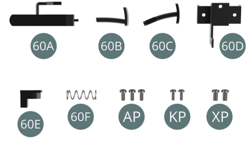
Parts of kit
- 60A Accelerator pedal
- 60B Clutch pedal
- 60C Brake pedal
- 60D Bracket
- 60E Switch
- 60F Return spring
- Screw AP M 1,7 x 4 mm (x 3)
- Screw KP M 1,4 x 4 mm (x 2)
- Screw XP M 2,3 x 4 mm (x 2)
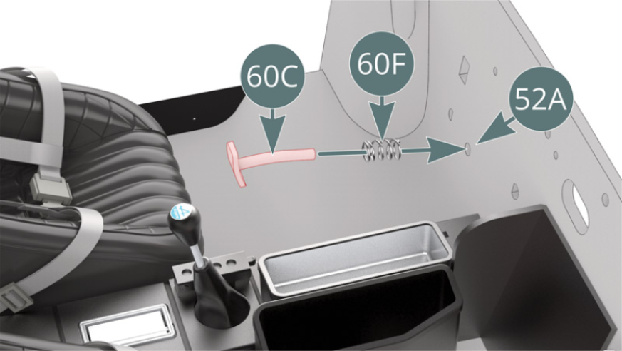
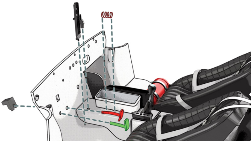
Step 1
Pass the brake pedal (60C) through the return spring (60F) and the front cabin floor panel (52A) (illustration above). Position the switch (60E) on the brake pedal (60C) from the other side of the front cabin floor panel (52A).

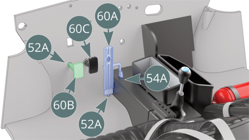
Step 2
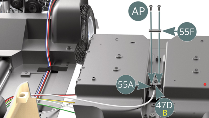
Place the accelerator pedal (60A) on the cabin floor (52A) and the central console (54A). Position the clutch pedal (60B) on the cabin floor (52A). Unscrew the two AP screws from the bottom plate (55A) and remove the mounting bracket (55F). Position cable connector B (47D) into the bottom plate housing (55A).
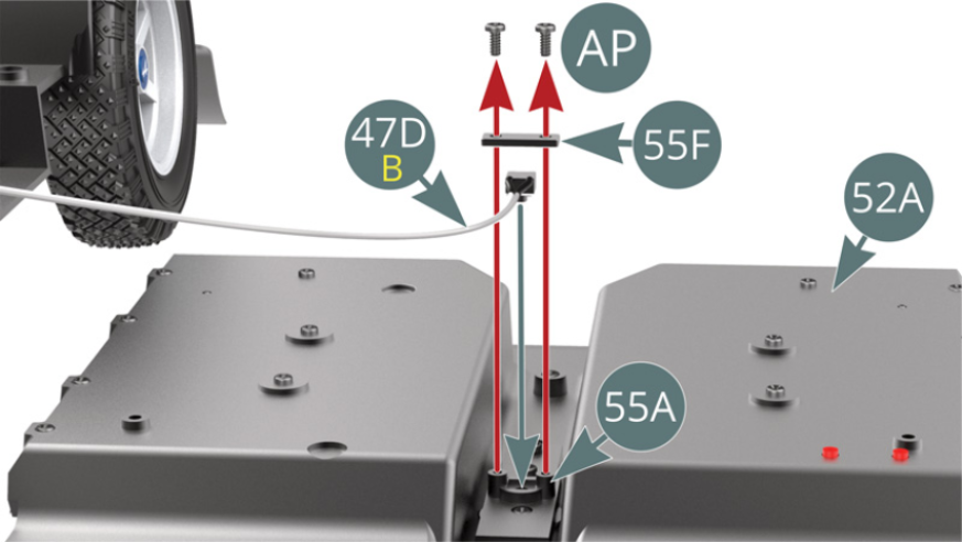
Step 3
Ensure that the connector of switch cable B (47D) is held in place with the bracket (55F) secured by two AP screws (illustrations above).
Step 4
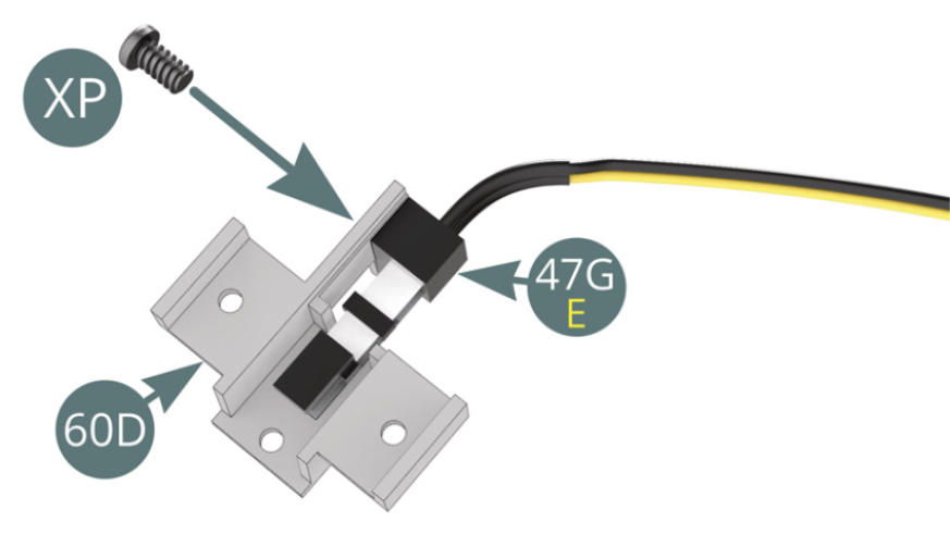
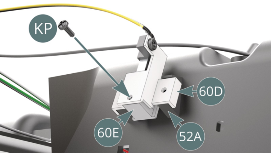
Place the switch cable connector E (47G) on the support (60D) and secure with an XP screw. Secure the bracket (60D) to the switch (60E) with a KP screw.
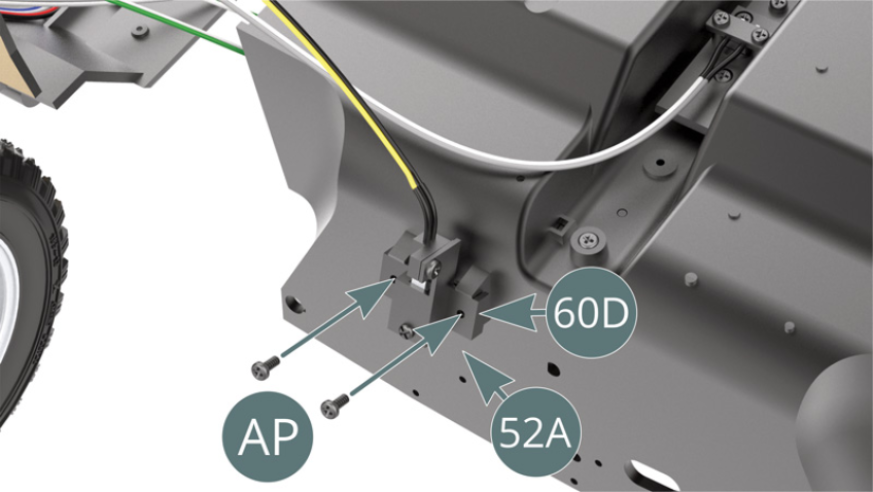
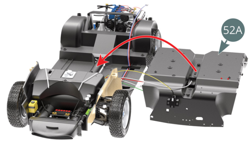
Step 5
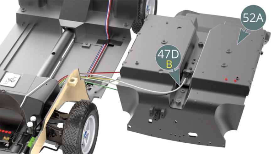
Secure the bracket (60D) to the front panel of the cabin floor (52A) with two AP screws. Position the cabin floor (52A) on the chassis with both cables connected.
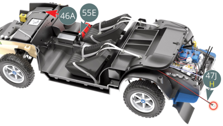
Step 6
Push the battery switch (positioned on the fuel tank - 46A) to the “On” position. Press the gear lever (55E) and check that the LED cable H / reverse light (47J) lights up. Return the battery switch (46A) to the “Off” position.
ASSEMBLY DIAGRAM
GENERAL VIEW