English
 français
 Deutsch
 español
 italiano
 português


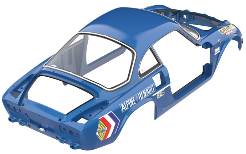
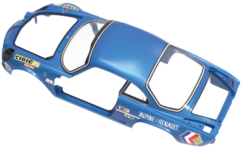
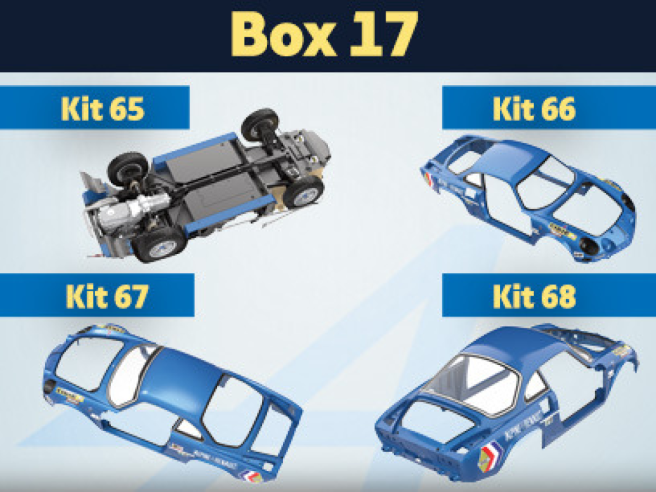
Box 17
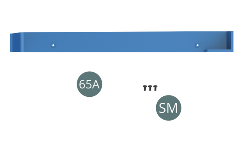
Parts of kit
- 65A Right rocker panel
Etape 1
- Screw SM M 1.7 x 3 mm (x 3)

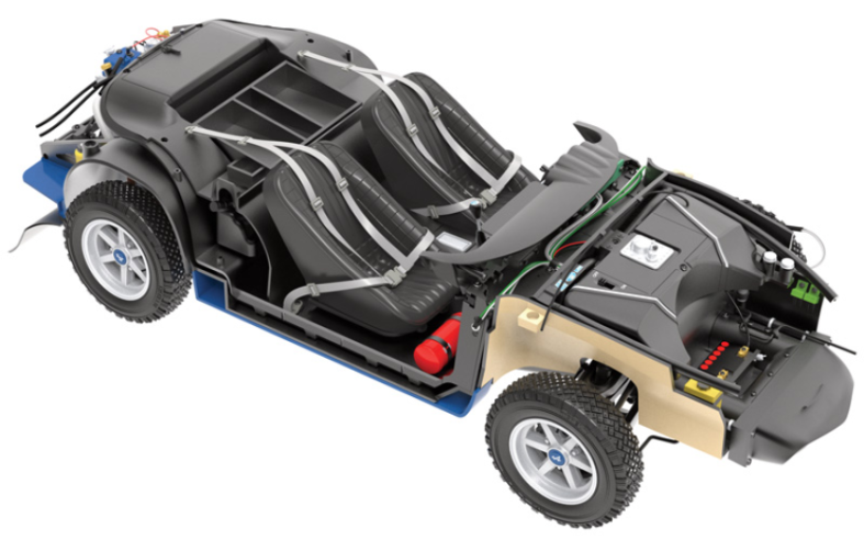
Positionner le bas de caisse droit 65A sur le plancher du châssis 39A et le fixer avec deux vis SM (Illustrations ci-dessus).
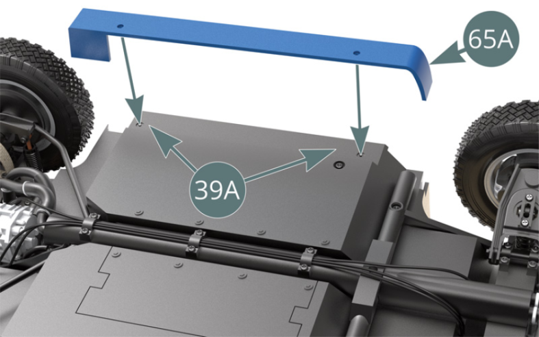
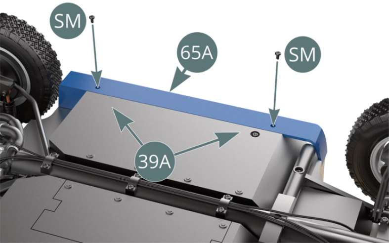
Schéma d’assemblage
Position the right rocker panel (65A) on the chassis floor (39A) and secure it with two SM screws (Illustrations above).

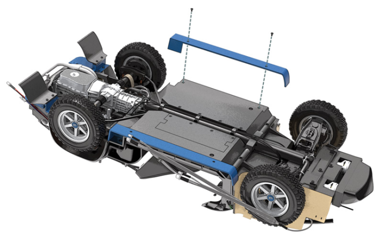
ASSEMBLY DIAGRAM

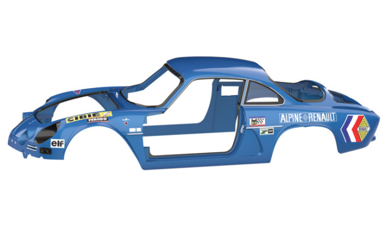
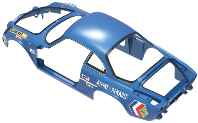
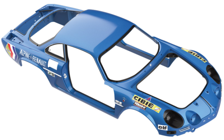
Kit 66
Parts of kit
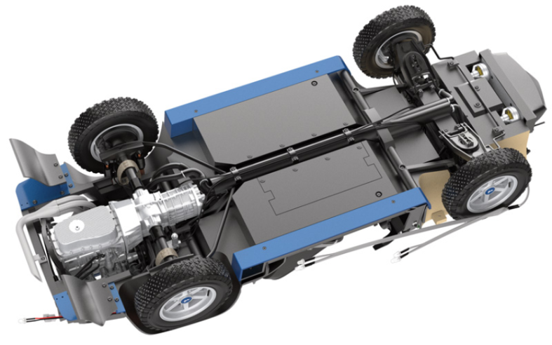
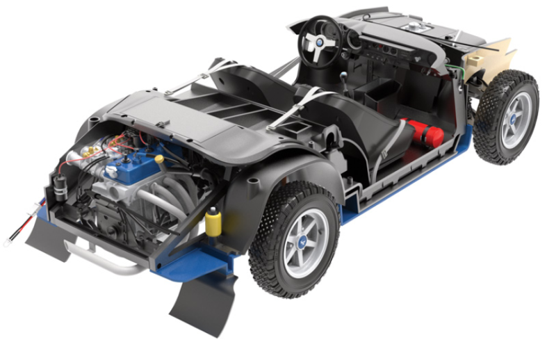
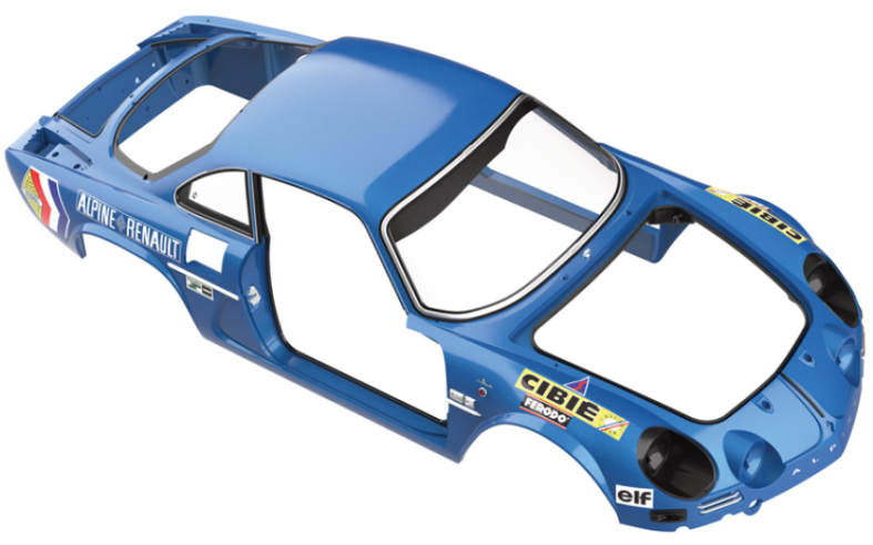
Vue générale
- 628E Attache
- 62F Contacteur de démarrage
- AP Vis M 1,7 x 4 mm (x 8)
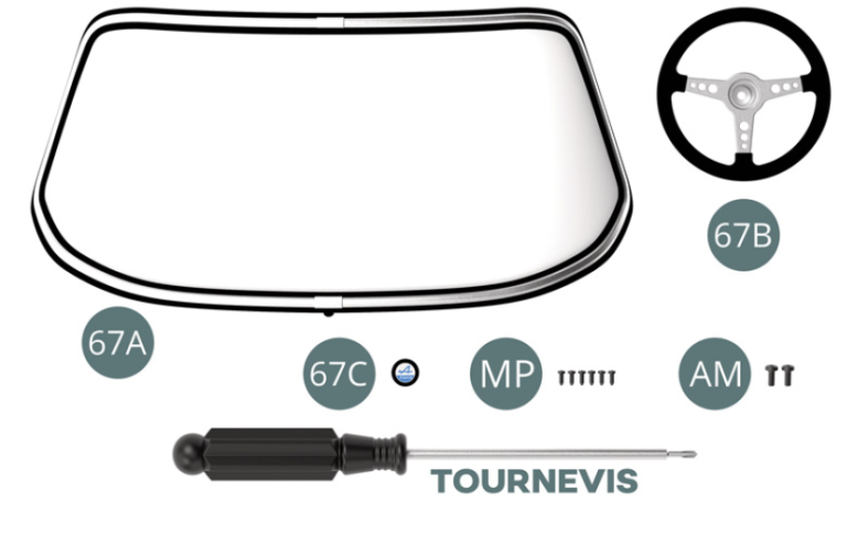
Kit 67 - Montage du volant de direction et du pare-brise
Parts of kit

Etape 1
- Screw MP M 1.2 x 3 mm (x 6)
- Screw AM M 1.7 x 4 mm (x 2)
- Screwdriver
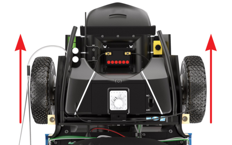
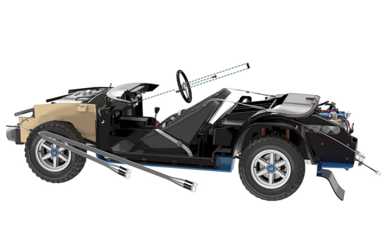
Disposer les roues bien droites et les maintenir dans cette position durant la fixation du volant de direction.

Etape 2
Position the wheels in a straight line and hold them in this position while you fit the steering wheel.
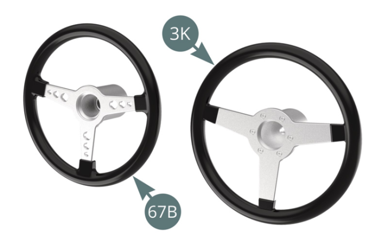
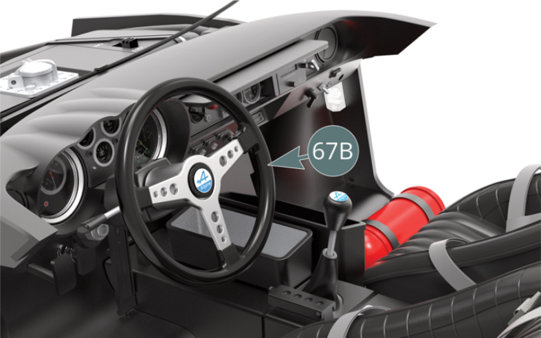
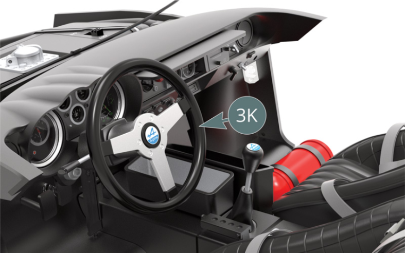
Choisir le modèle de volant 67B ou 3K selon son goût. Le montage est identique pour les deux types.

Etape 3
Choose the steering wheel model (67B or 3K) according to your preference. The assembly is identical for both types.
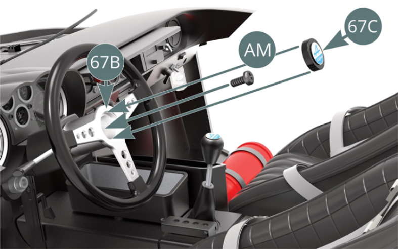
Positionner le volant de direction 67B ou 3K sur la colonne de direction 53A, puis le fixer avec une vis AM. Positionner l’écusson de volant 67C sur le volant de direction 67B ou 3K (illustrations ci-dessus).
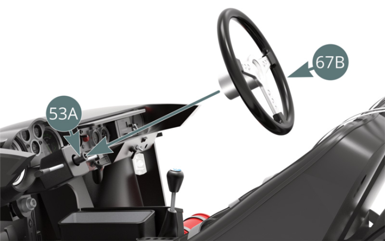

Etape 4
Place the steering wheel (67B or 3K) on the steering column (53A), then secure it with an AM screw. Position the steering wheel emblem (67C) on the steering wheel (67B or 3K) - illustrations above.

Le volant de direction 67B est monté.
Etape 5
The steering wheel (67B) is installed.

Le volant de direction 3K est monté.
Etape 6
The steering wheel (3K) is installed.

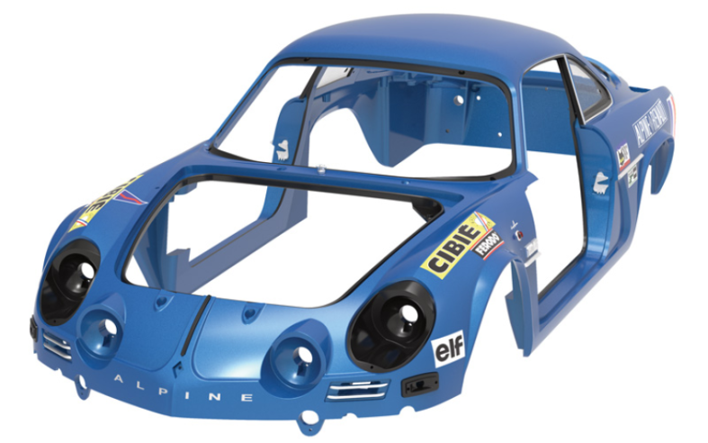
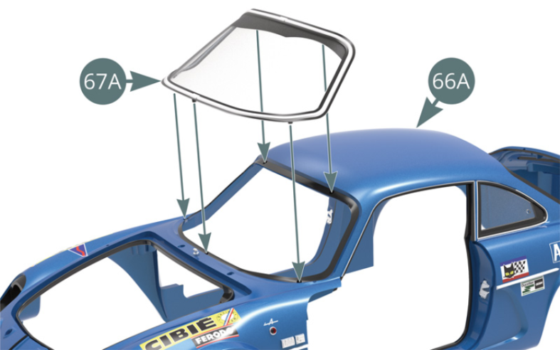
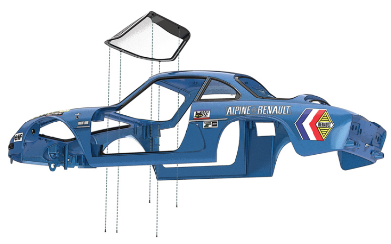
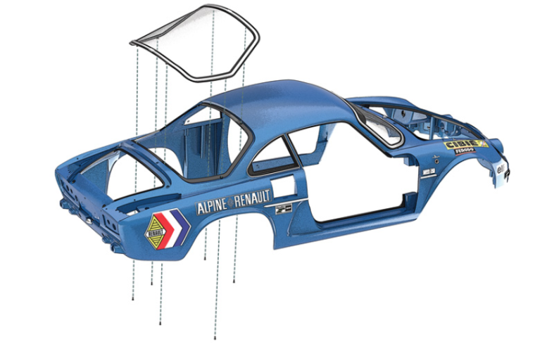
Positionner le pare-brise 67A sur la carrosserie 66A et le fixer par en-dessous avec cinq vis MP (illustrations ci-dessus).

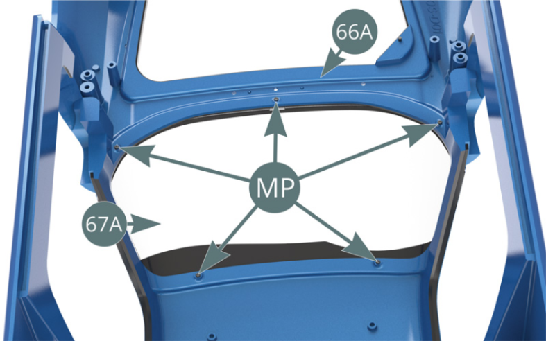
Schéma d’assemblage
Place the windshield (67A) on the bodywork (66A) and secure it from below with five MP screws (illustrations above).
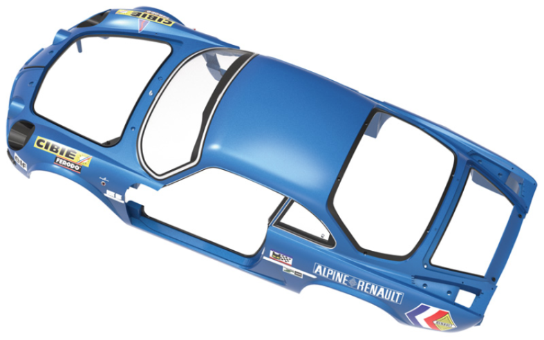
Vue générale

Kit 68 - Montage de la vitre arrière
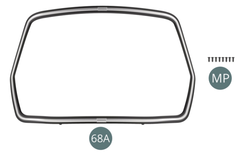
Parts of kit

Etape 1
- Screw MP M 1.2 x 3 mm (x 8)
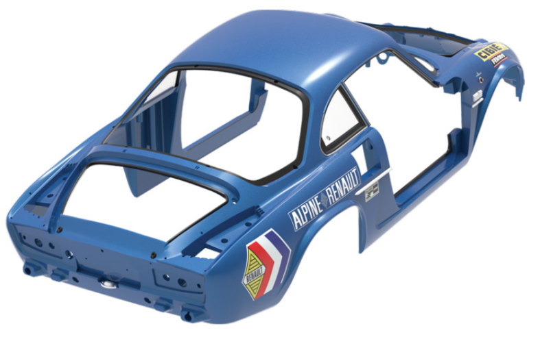
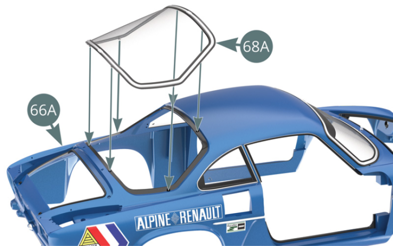
Positionner la vitre arrière 68A sur la carrosserie 66A et la fixer par en-dessous avec six vis MP (illustrations ci-dessus et ci-dessous).


Schéma d’assemblage
Position the rear window (68A) on the body (66A) and secure it from below with six MP screws (illustrations above and below).
ASSEMBLY DIAGRAM