English
 français
 Deutsch
 español
 italiano
 português


Box 19

Parts of kit
- 73A Left ventilation vent
- 73B Right ventilation vent
- 73C Left ventilation grill
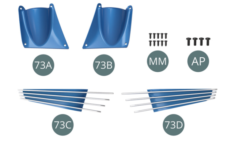
Etape 1
- 73D Right ventilation grill
- Screw MM M 1.2 x 3 mm (x 10)
- Screw AP M 1.7 x 4 mm (x 4)

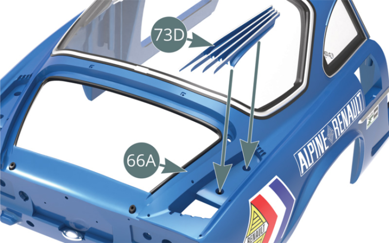
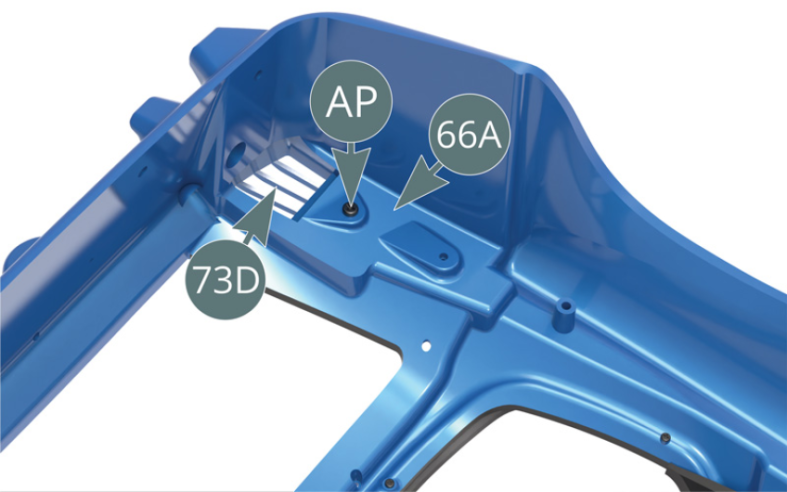
Positionner la grille d’aération droite 73D sur l’arrière de la carrosserie 66A et la fixer par en-dessous avec une vis AP (illustrations ci-contre et ci-dessous).


Etape 2
Position the right ventilation grill (73D) on the rear of the bodywork (66A) and secure it from below with an AP screw (illustrations opposite and below).
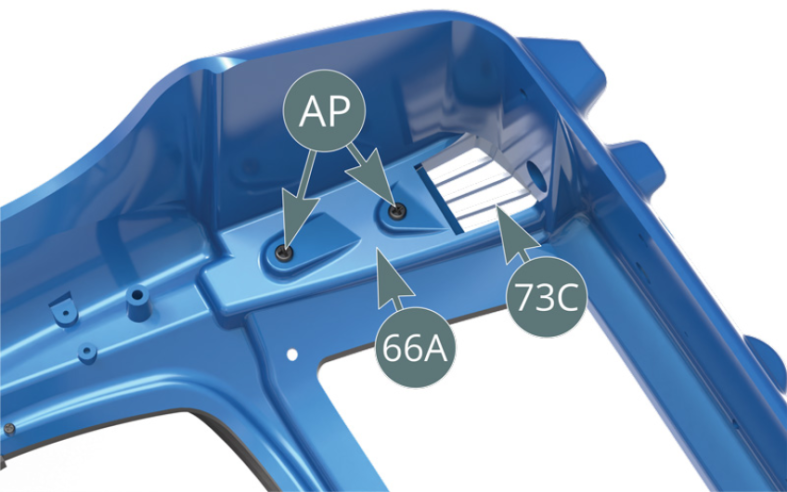
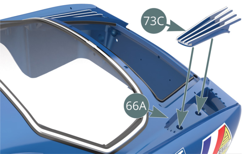
Positionner la grille d’aération gauche 73C sur l’arrière de la carrosserie 66A et la fixer par en-dessous avec deux vis AP (illustrations ci-contre et ci-dessous).

Etape 3
Place the left ventilation grill (73C) on the rear of the bodywork (66A) and secure it from below with two AP screws (illustrations opposite and below).

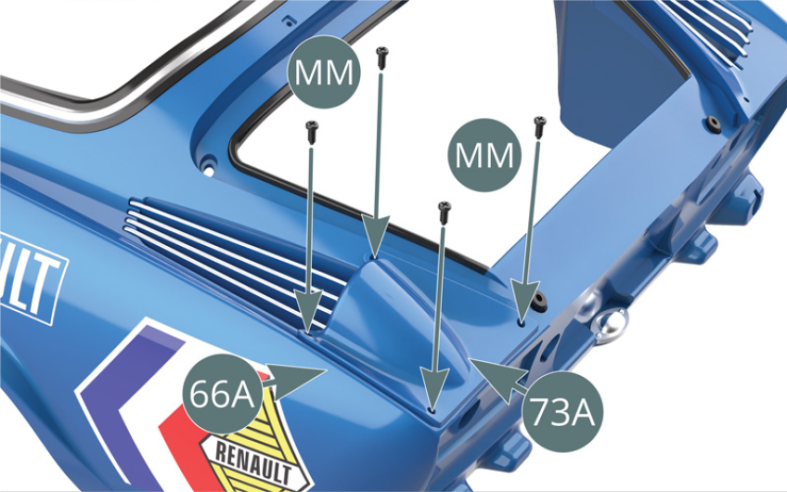
Positionner l’écope d’aération gauche 73A sur la carrosserie 66A et la fixer avec quatre vis MM.

Etape 4
Place the left ventilation vent (73A) on the bodywork (66A) and secure with four MM screws.
Positionner l’écope d’aération droite 73B sur la carrosserie 66A et la fixer avec quatre vis MM.
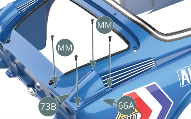
Schéma d’assemblage
Place the right ventilation vent (73B) on the bodywork (66A) and secure with four MM screws.

ASSEMBLY DIAGRAM
Kit 74 - Assemblage et montage du feu arrière gauche
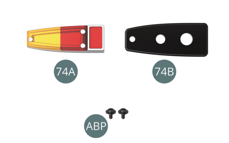
Parts of kit

Etape 1
- Screw ABP M 1.4 x 3 x 4 mm (x 2)
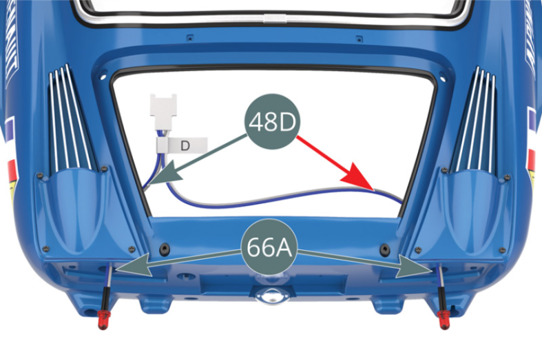
Engager les LEDs rouges du câble D-48D (déconnecté lors de l’étape 48) à travers les trous situés de chaque côté du panneau arrière de la carrosserie 66A. Noter que le fil le plus long est destiné au côté droit (flèche rouge).
Etape 2
Engage the red LEDs of cable D (48D) (disconnected in step 4 of components 48) through the openings located on each side of the rear panel of the body (66A). Note that the longest wire is intended for the right side (red arrow).

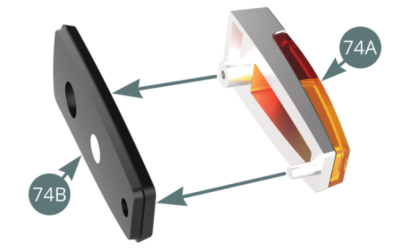
Positionner le feu arrière gauche 74A sur le support arrière gauche 74B.

Etape 3
Place the left rear light (74A) on the left rear light bracket (74B).
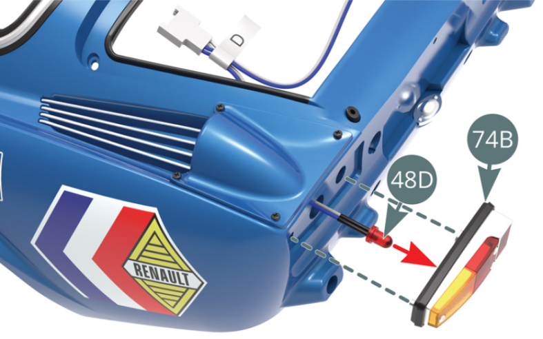
Insérer la LED gauche (fil le plus court) du câble D-48D dans le support arrière gauche 74B, puis fixer le feu arrière gauche 74A et le support 74B sur le côté gauche du panneau arrière de la carrosserie 66A (illustrations ci-contre et ci-dessous).


Etape 4
Insert the left LED (shortest wire) of the cable D (48D) into the left rear bracket (74B), then attach the left rear light (74A) and bracket (74B) to the left side of the rear panel of the bodywork (66A) (illustrations opposite and below).
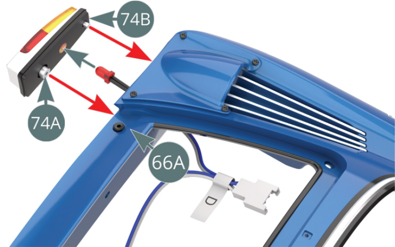
Fixer le feu arrière gauche sur la carrosserie 66A depuis l’intérieur avec une vis ABP.
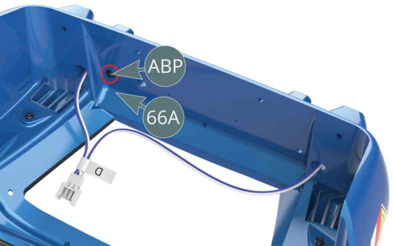
Schéma d’assemblage
Secure - from the inside - the left rear light (74A) to the bodywork (66A) with an ABP screw.

ASSEMBLY DIAGRAM

Kit 75 - Assemblage et montage du feu arrière droit
Parts of kit
Etape 1
- Screw ABP M 1.4 x 3 x 4 mm (x 2)
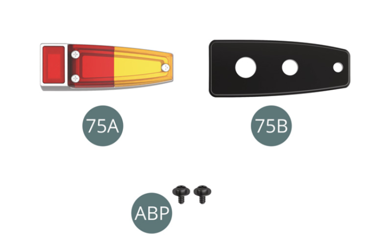
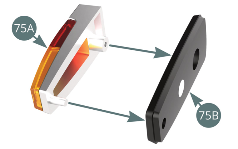
Positionner le feu arrière droit 75A sur le support arrière droit 75B.

Etape 2
Place the right rear light (75A) on the right rear support (75B).
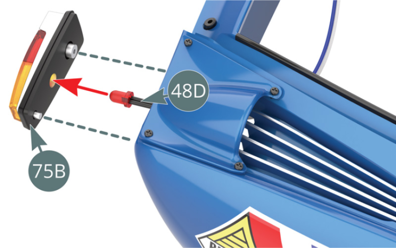
Insérer la LED droite (fil le plus long) du câble D-48D dans le support arrière droit 75B.

Etape 3
Insert the right LED (longest wire) of the cable D (48D) into the right rear light bracket (75B).
Positionner le support droit 75B et le feu arrière droit 75A sur le côté droit du panneau arrière de la carrosserie 66A, puis les fixer depuis l’intérieur avec une vis ABP (illustrations ci-dessus).
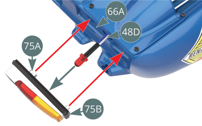
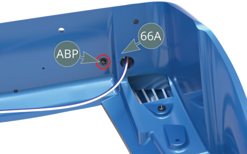
Schéma d’assemblage
Position the right bracket (75B) and the right rear light (75A) on the right side of the rear panel of the bodywork (66A), then secure them from the inside with an ABP screw (illustrations above).

ASSEMBLY DIAGRAM
Kit 76 - Assemblage et montage du ventilateur de radiateur d’huile. Fixation du câble des feux arrière
Parts of kit

Etape 1
- 76D Adhesive tape (x 3)
- Screw UP M 1.7 x 6 mm (x 2)
- Screw NP M 1.2 x 4 mm (x 2)
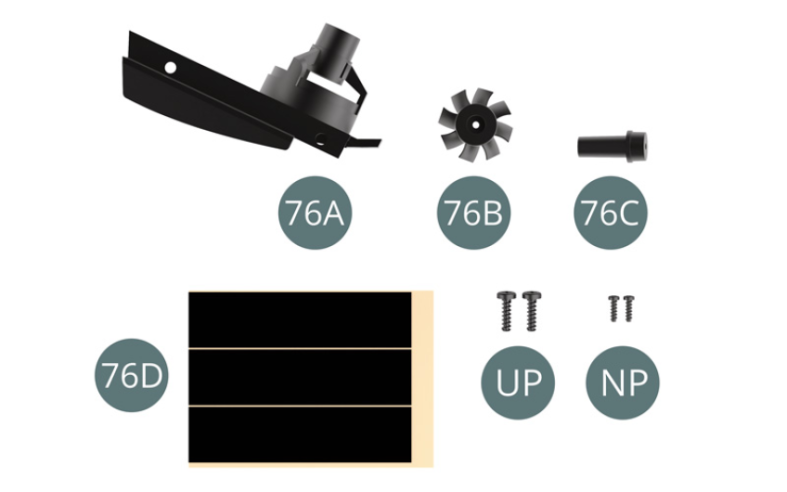
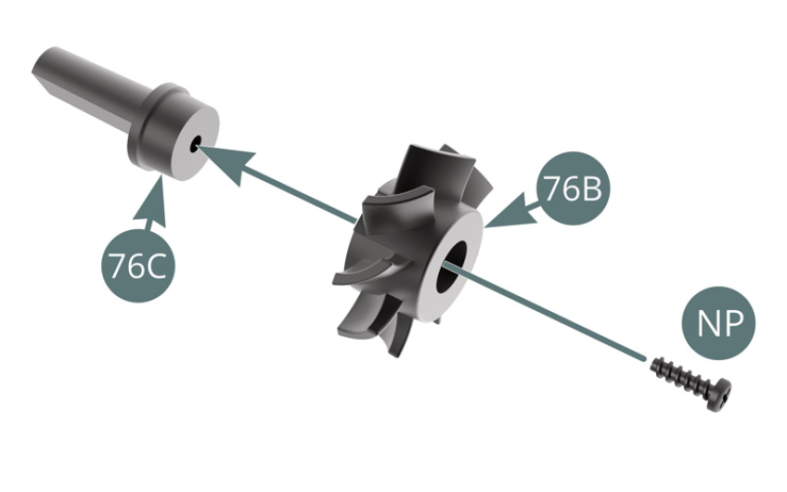
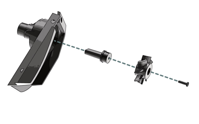
Positionner l’hélice de ventilateur 76B sur l’axe 76C et la fixer avec une vis NP.

Etape 2
Position the fan propeller (76B) on the axis (76C) and secure with an NP screw.
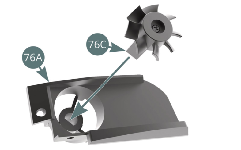
Positionner l’axe 76C sur le support du boîtier de ventilateur de radiateur d’huile 76A.

Etape 3
Place the axis (76C) on the oil radiator fan housing bracket (76A).
Positionner le boîtier de ventilateur de radiateur d’huile 76A sous la carrosserie 66A et le fixer avec une vis UP.
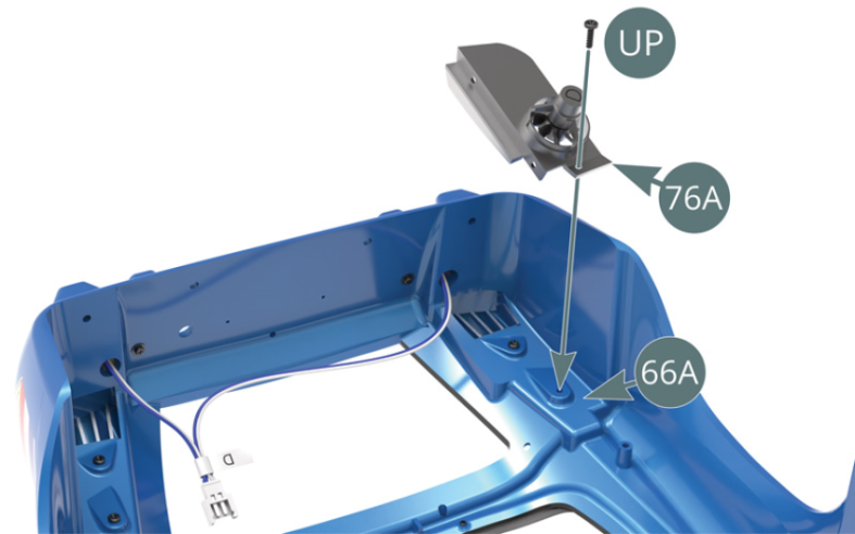
Etape 4
Position the oil radiator fan housing (76A) underneath the bodywork (66A) and secure with a UP screw.

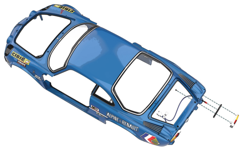
Guider le fil le plus long du câble D-48D le long de l’intérieur du panneau arrière de la carrosserie 66A et le fixer avec deux rubans adhésifs 76D.
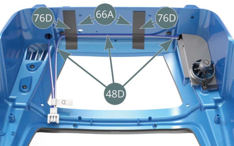
Schéma d’assemblage
Guide the longest wire of cable D (48D) along the inside of the rear panel of the bodywork (66A) and secure it with two adhesive tapes (76D).

Vue générale