English
 français
 Deutsch
 español
 italiano
 português


Box 2
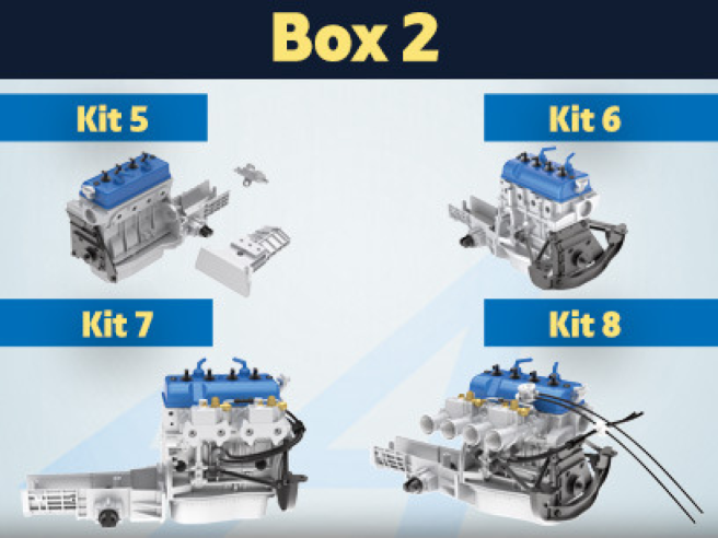
Kit 5 - Assembly of the engine
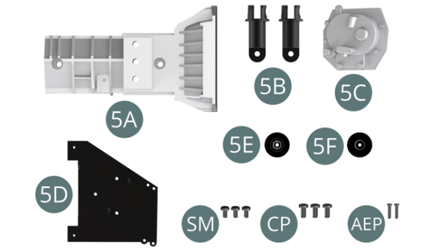
Parts of kit
- 5A Gearbox housing top
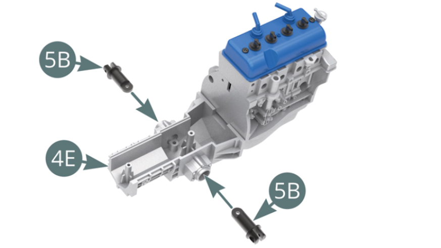
- 5B Transmission joint (x 2)
- 5C Gearbox rear cover
- 5D Engine spacer
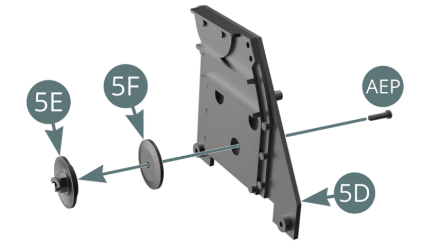
- 5E Engine pulley outer rim
- 5F Engine pulley inner rim
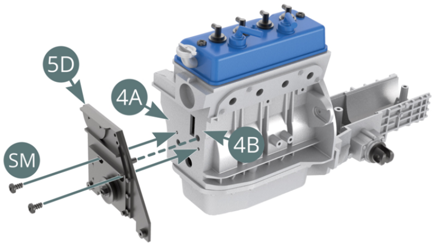
- SM M 1.7 x 3 mm screw (x 3)
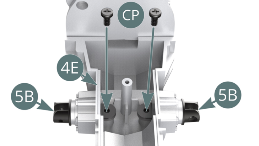
- CP M 2.0 x 4 mm screw (x 3)
- AEP Screw M 1.2 x 5 mm (x 2)
STEP 1
Position the two transmission joints (5B) in the housings of the lower gearbox housing (4E) and secure them with two CP screws (shown below).
STEP 2
Position the inner (5F) and outer (5E) motor pulley rims on the spacer (5D) and secure with an AEP screw.
Position the spacer (5D) on the left (4A) and right (4B) end of the motor block and secure with two SM screws.
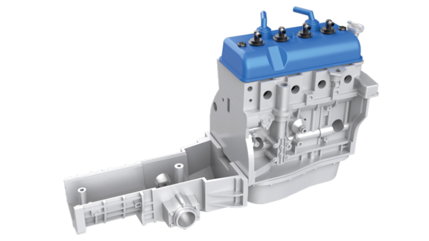
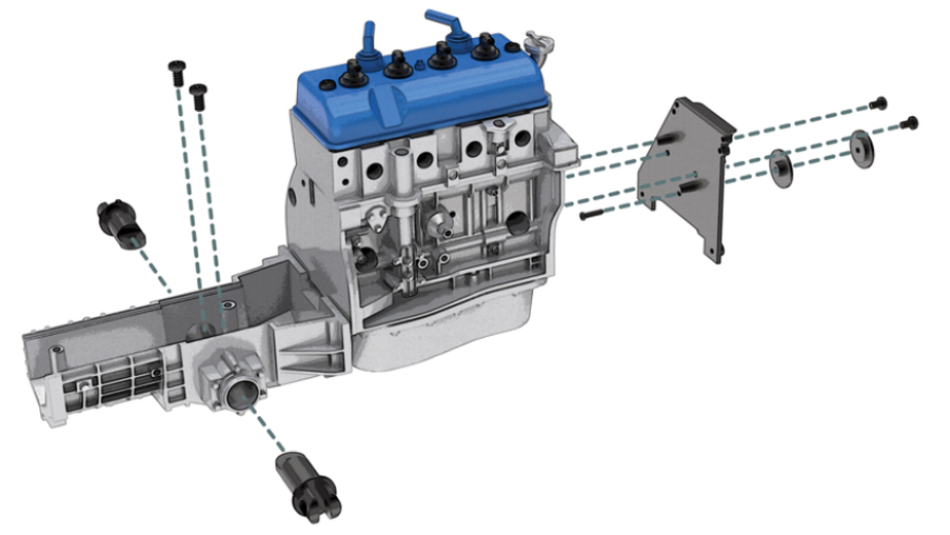
ASSEMBLY DIAGRAM
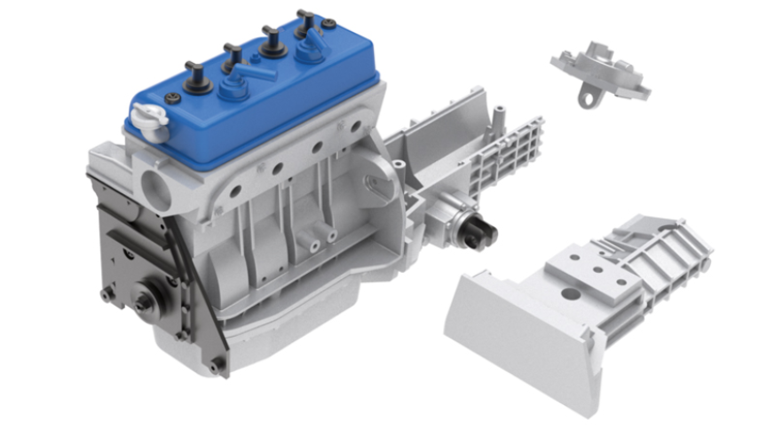
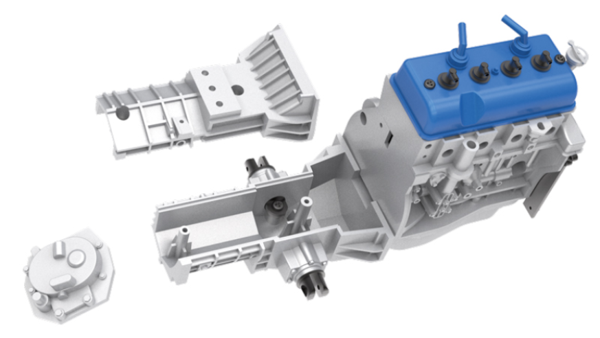
GENERAL VIEW
Kit 6 - Mounting of the motor support
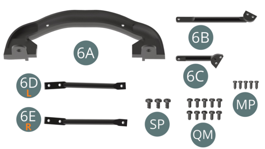
Parts of kit
- 6A Engine support frame
- 6B Upper right engine support arm
- 6C Upper left engine support arm
- 6D Lower left engine support arm L
- 6E Lower right motor support arm D
- SP Screw M 1.7 x 3 mm (x 3)
- QM Screw M 1.4 x 3 mm (x 10)
- MP Screw M 1.2 x 3 mm (x 5)
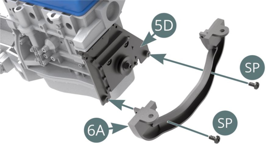
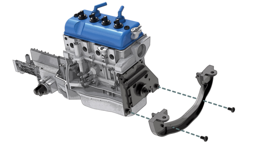
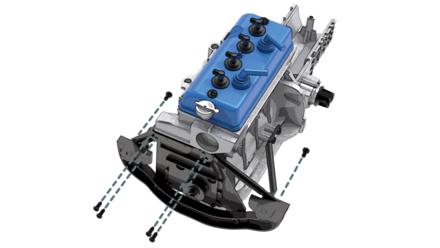
STEP 1
Position the engine support bracket (6A) on the spacer (5D) and secure with two SP screws. Position the left lower engine support arm (6D) onto the left engine block (4A) and support bracket (6A) and secure with three QM screws.

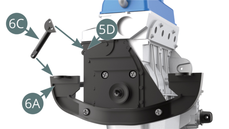
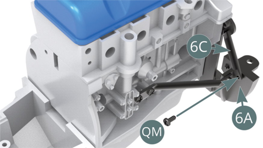
STEP 2
Position the left upper engine support arm (6C) onto the spacer (5D) and support bracket (6A). Attach the lower end of the left upper engine support arm (6C) to the engine support bracket (6A) with a QM.
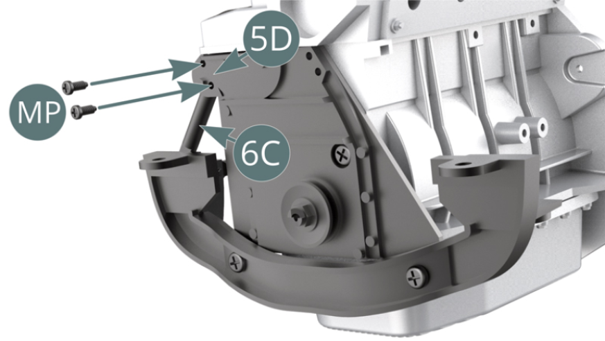
STEP 3
Attach the upper end of the left upper arm (6C) to the spacer (5D) with two MP screws.
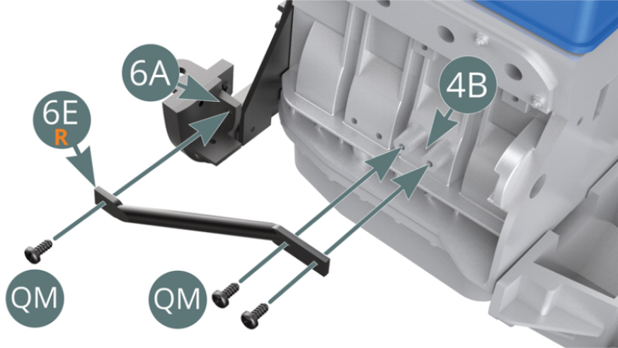
Position the lower right engine support arm (6E) onto the right engine block (4B) and support bracket (6A) and secure with three QM screws.
STEP 4
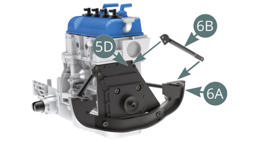
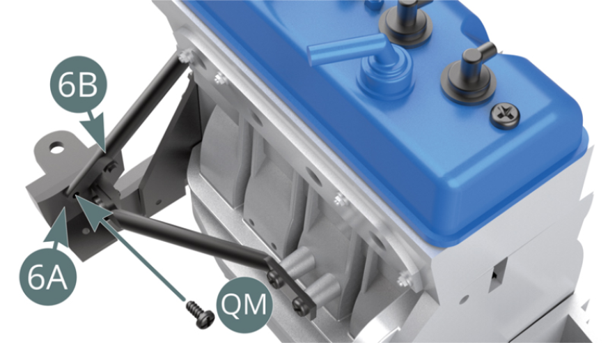
Position the right upper engine support arm (6B) onto the spacer (5D) and support bracket (6A). Attach the lower end of the upper right arm (6B) to the motor support cradle 6A with a QM screw.
STEP 5
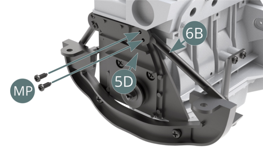
Attach the upper right arm end (6B) to the spacer (5D) with two MP screws.
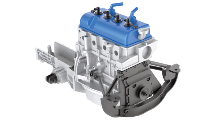
ASSEMBLY DIAGRAM
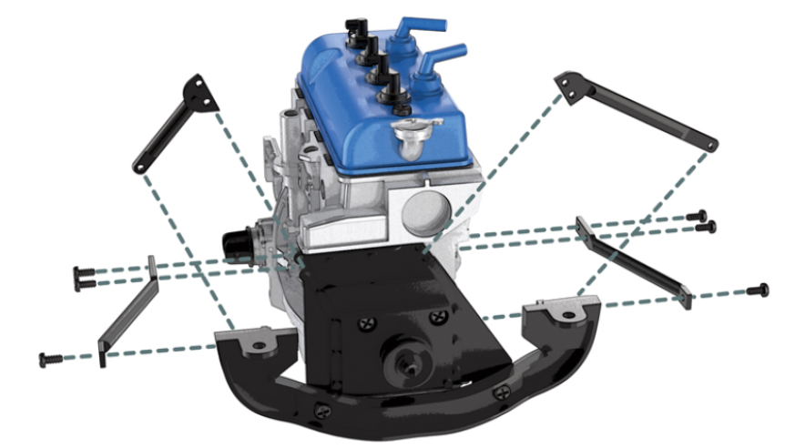
GENERAL VIEW
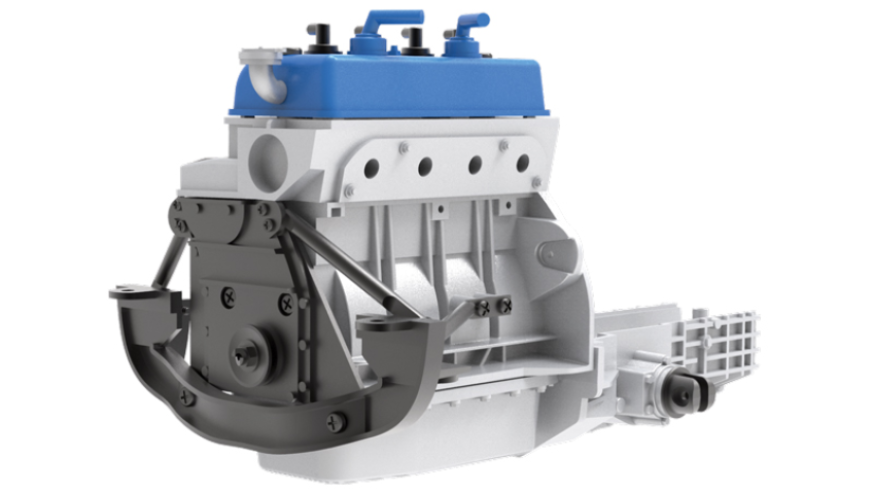
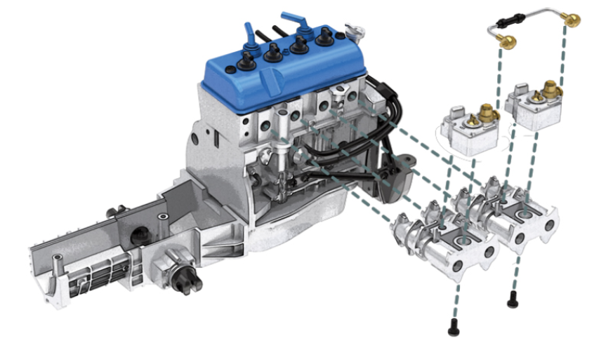
Kit 7 - Carburettor assembly and engine installation
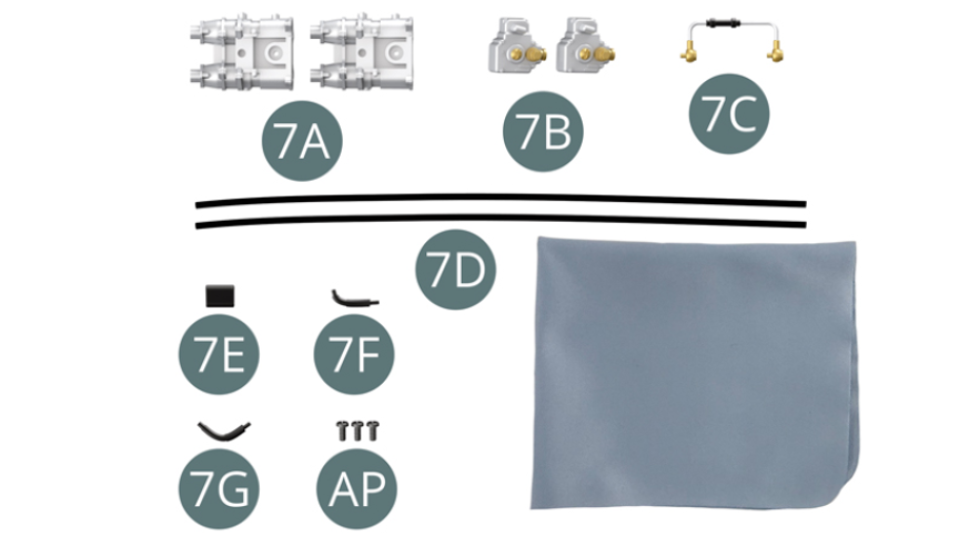
Parts of kit
- 7A Intake manifold (x 2)
- 7B Carburettor (x 2)
- 7C Connecting hose
- 7D Oil line (x 2)
- 7E Clamp
- 7F Elbow fitting
- 7G Elbow fitting
- AP Screw M 1.7 x 4 mm (x 3)
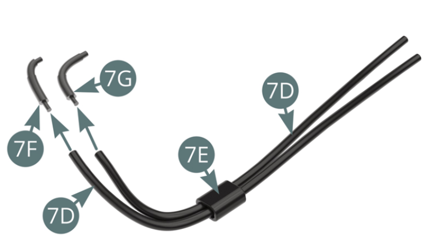
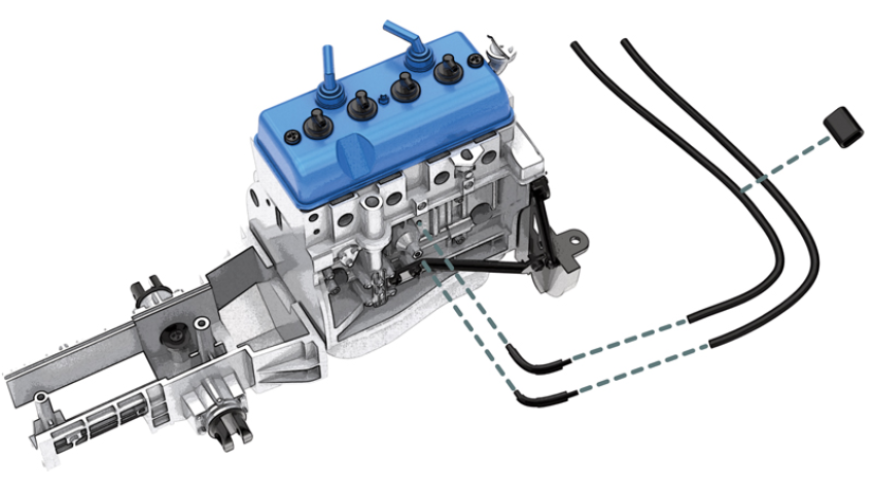
STEP 1
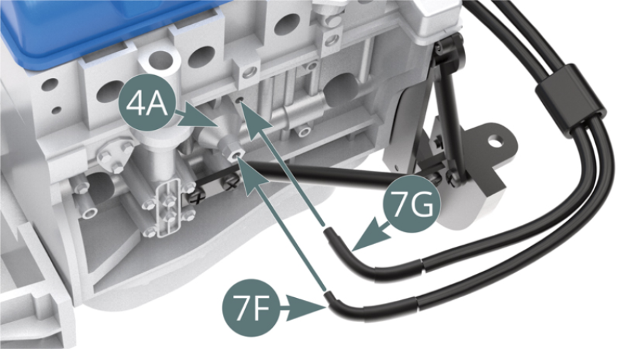
Pass the two oil lines (7D) through the clamp (7E). Position the two oil lines (7D) on the elbows (7F) and (7G).
Position the elbows (7F) and (7G) on the left engine block (4A).
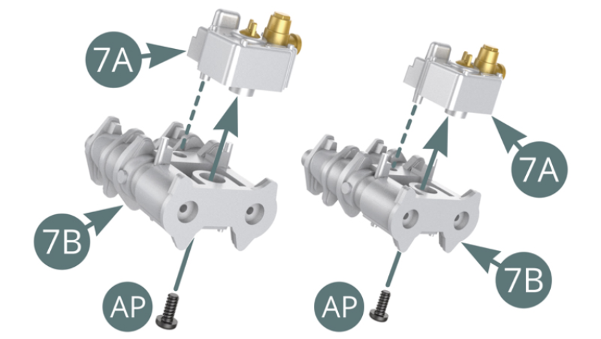
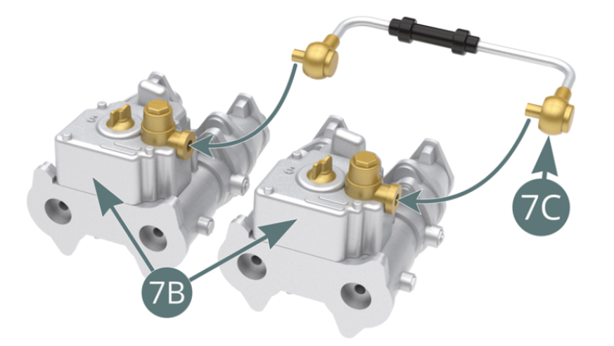
STEP 2
Position the intake manifolds (7A) on the carburettors (7B) and secure them with two AP screws. Connect the two carburettors (7B) with the connecting hose (7C).
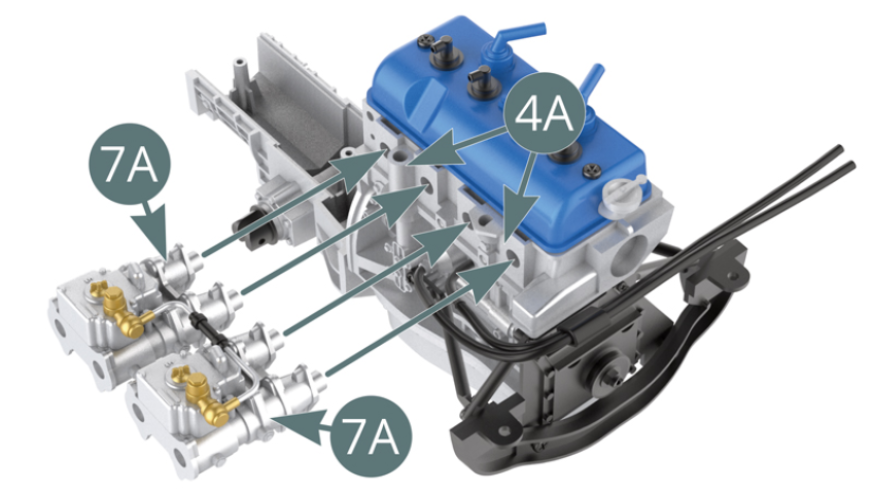
STEP 3
Position the intake manifolds (7A) on top of the left engine block (4A).
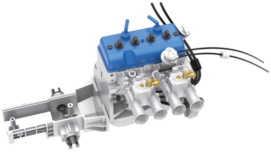
ASSEMBLY DIAGRAM
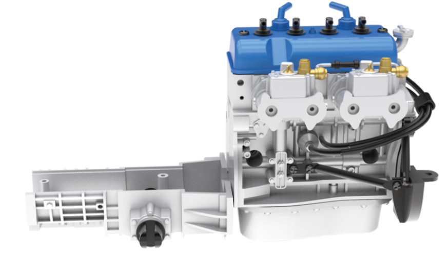
GENERAL VIEW
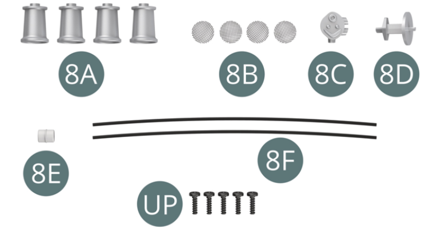
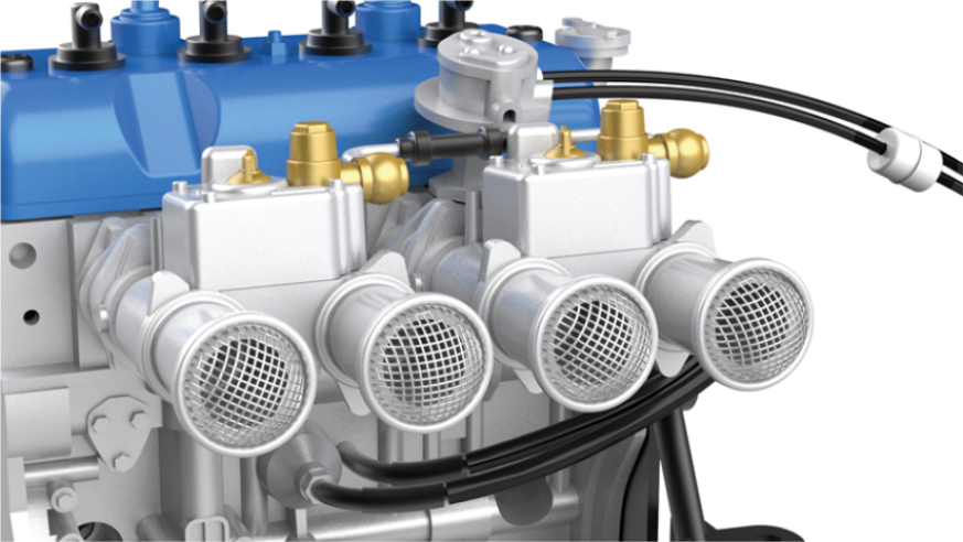
Kit 8 - Assembly of the air intake trumpets and oil pump and installation on the engine block
Parts of kit
- 8A Air intake trumpet (x 4)
- 8B Air filter grill (x 4)
- 8C Oil pump
- 8D Oil pump support
- 8E Oil filter
- 8F Oil line (x 2)
- Screw UP M 1.7 x 6 mm (x 5)
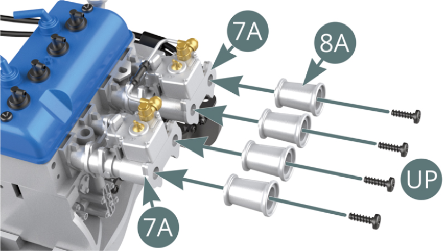
STEP 1
Position four air intake trumpets (8A) on the intake manifold (7A) and secure with four UP screws.
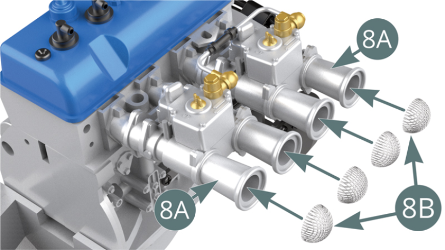
Position the four air filter grilles (8B) on the air intake trumpets (8A).
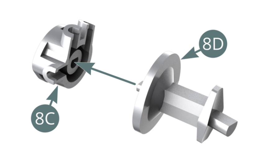
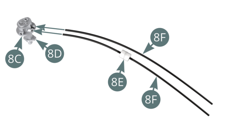
STEP 2
Position the oil pump (8C) on the oil pump support (8D). Run one oil line (8F) through the oil filter (8E). Position the two oil lines (8F) on the oil pump (8C).
STEP 3
Position the oil pump support (8D) on top of the engine block (4C). The air intake trumpets and oil pump are positioned on the engine block.

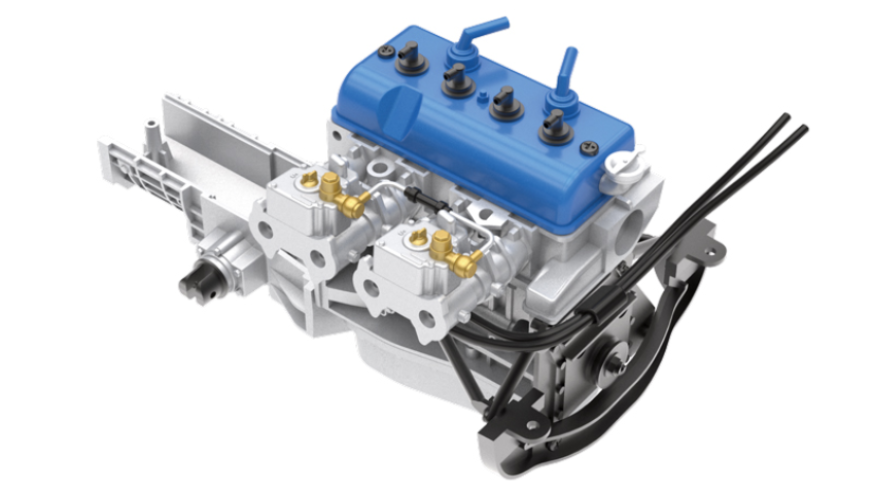
ASSEMBLY DIAGRAM
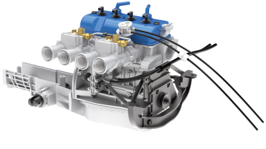
GENERAL VIEW