English
 français
 Deutsch
 español
 italiano
 português


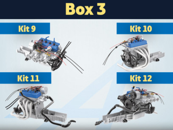
Box 3
Kit 9 - Assembly and installation of the alternator and ignition distributor to the engine
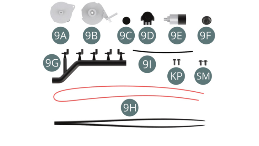
Parts of kit
- 9A Alternator
- 9B Alternator bracket
- 9C Cover
- 9D Distributor head
- 9E Ignition distributor
- 9F Vacuum valve
- 9G Distributor terminal (x 5)
- 9H High voltage cable
- 9I High voltage cable
- Tweezers
- Screw KP M 1.4 x 4 mm (x 2)
- Screw SM M 1.7 x 3 mm (x 2)
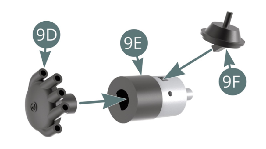
STEP 1
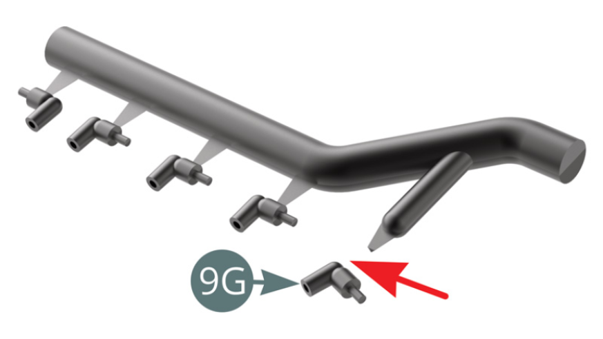
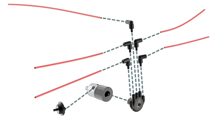
Position the distributor head (9D) and vacuum valve (9F) onto the ignition distributor (9E). Detach the five distributor terminals (9G) from the sprue.
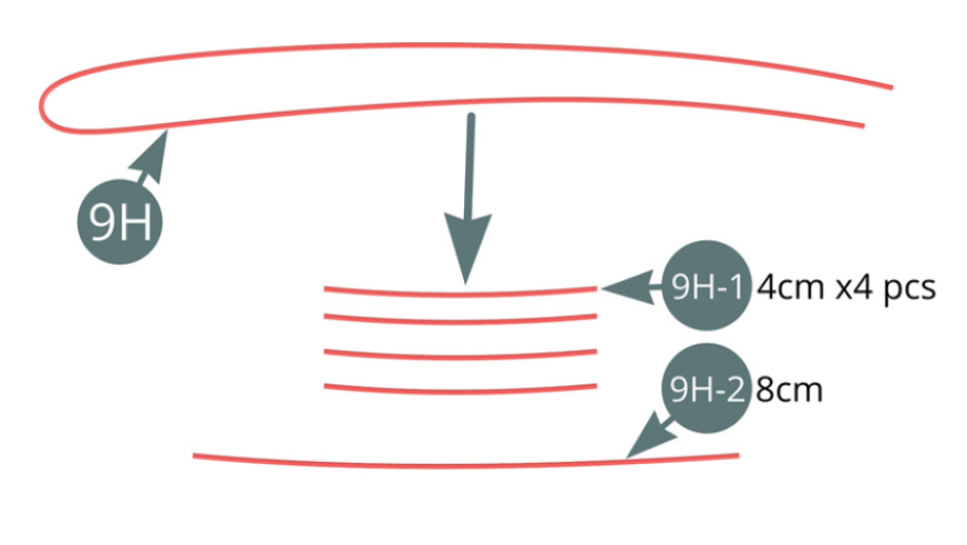
Etape 2
Cut four sections of 4 cm length (9H-1) and one section of 8 cm length (9H-2) from the high voltage cable (9H).
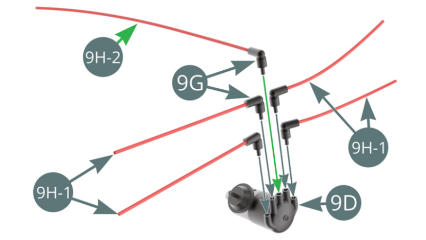
Connect one end of the four high voltage cables (9H-1) and cable (9H-2) - green arrow - to the distributor terminals (9G). Position the terminals (9G) on the distributor head (9D).
STEP 3
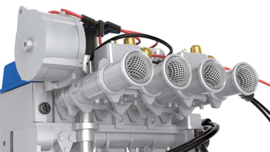
Position the ignition distributor (9E) on top of the engine block (4C).

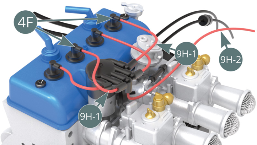
Connect the first and third high voltage cables (9H-1) to the first and third spark plugs (4F) respectively - working from left to right.
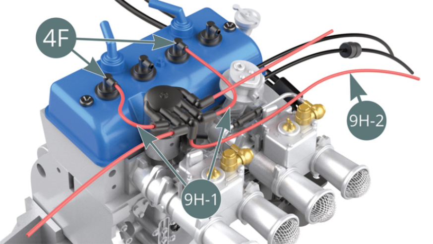
STEP 4
Connect the second and fourth high voltage cable (9H-1) to the second and fourth spark plug (4F) respectively - working from left to right.
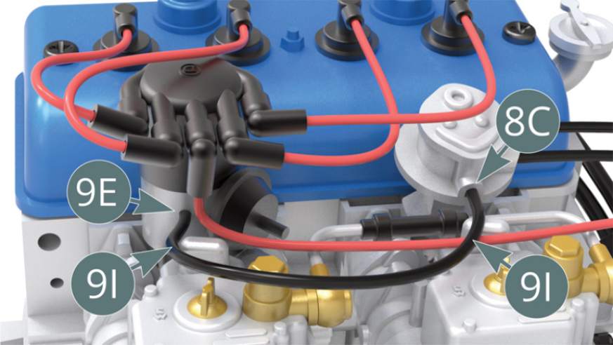
Connect the high voltage cable (9I) to the ignition distributor (9E) and oil pump (8C).
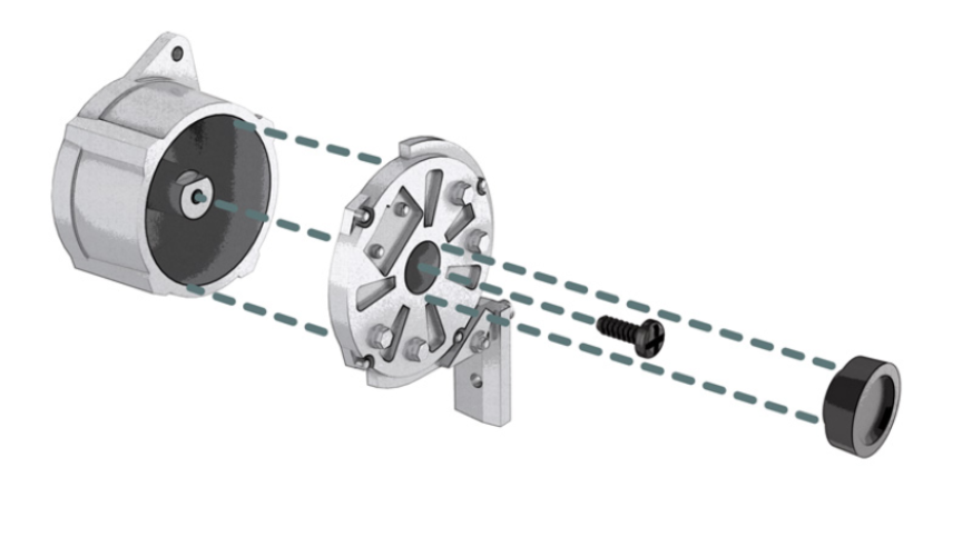
STEP 5
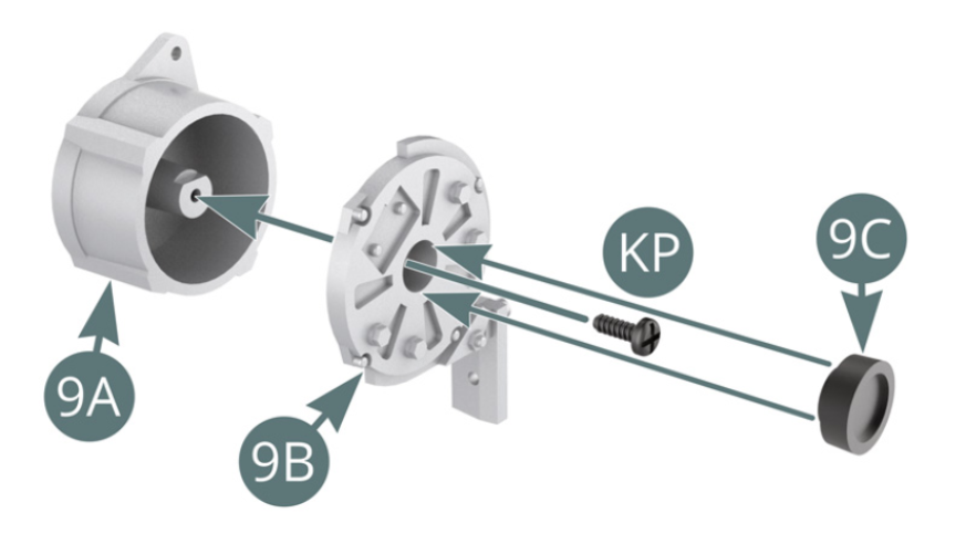
Position the alternator (9A) onto the alternator bracket (9B) and secure with a KP screw. Position the cover (9C) onto the alternator bracket (9B).
STEP 6
Position the alternator bracket (9B) onto the top of the engine block (4C) and secure with an SM screw (shown opposite and below).

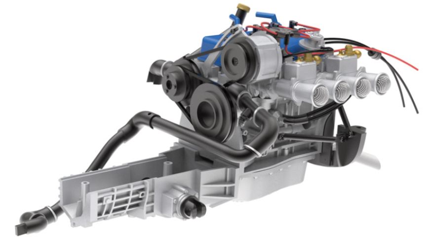
ASSEMBLY DIAGRAM
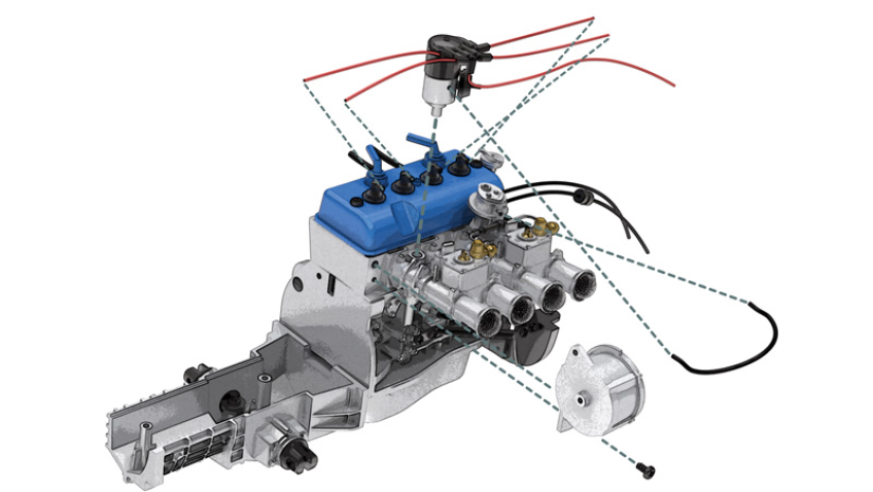
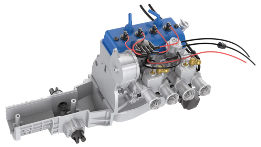
GENERAL VIEW
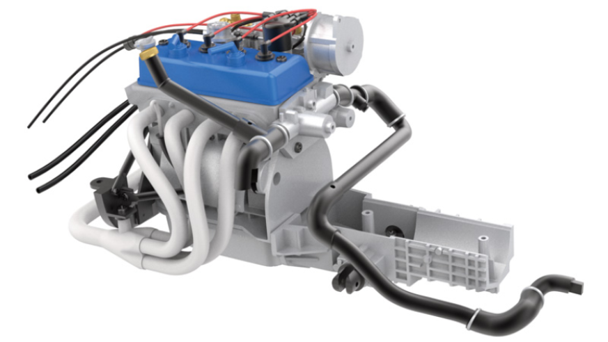
Kit 10 - Assembly of the starter and exhaust manifold
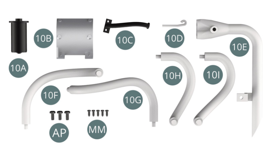
Parts of kit
- 10A Starter
- 10B Heat shield
- 10C Dipstick tube
- 10D Oil dipstick
- 10E Connecting pipe
- 10F Exhaust manifold #1
- 10G Exhaust manifold #2
- 10H Exhaust manifold #3
- 10I Exhaust manifold #4
- Screw AP M 1.7 x 4 mm (x 3)
- Screw MM M 1.2 x 3 mm (x 5)
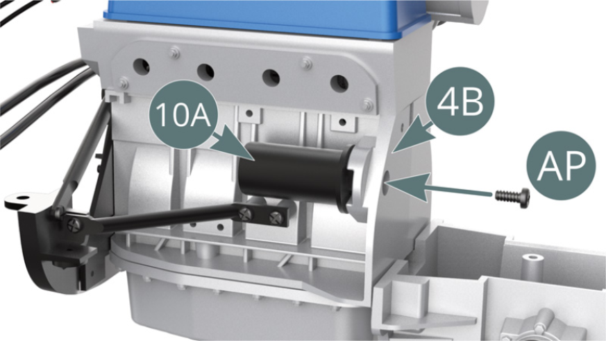
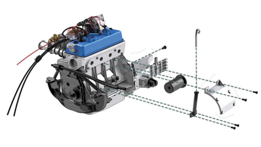
STEP 1
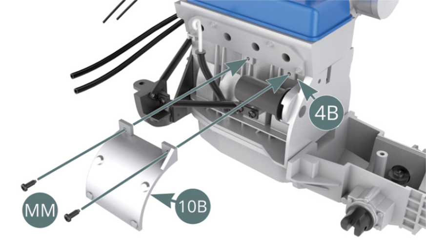
Position the starter (10A) to the right hand engine block (4B) and secure with an AP screw.
Insert the dipstick (10D) into the dipstick tube (10C). Position the dipstick tube (10C) on the right-hand engine block (4B) and secure with two MM screws.

STEP 2
Position the heat shield (10B) on the engine block right hand side (4B) and secure with two MM screws.
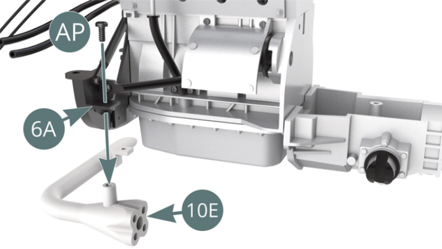
Position the connection pipe (10E) on the engine support frame (6A) and secure it with an AP screw.
STEP 3
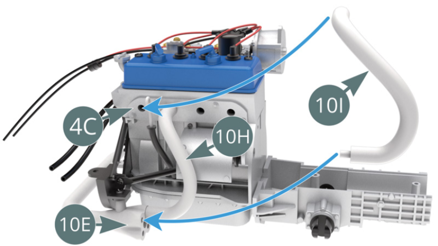
Position Exhaust Manifold #3 (10H) on connecting tube (10E) and top of engine block (4C) - blue arrows.
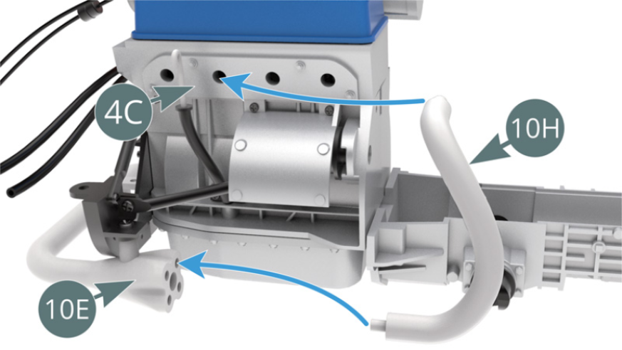
Position exhaust manifold #4 (10I) on connection tube (10E) and top of engine block (4C) - blue arrows.
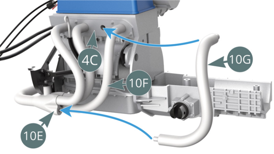
STEP 4
Position Exhaust Manifold #1 (10F) on connecting tube (10E) and top of engine block (4C) - blue arrows.
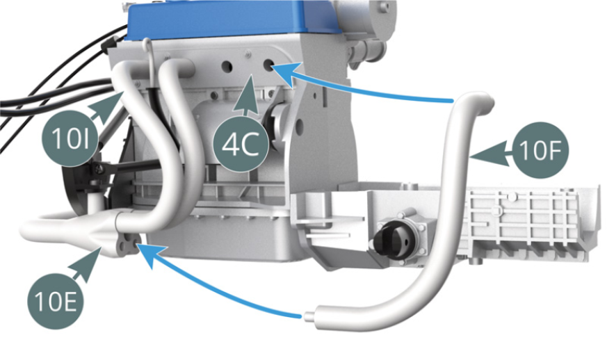
Position Exhaust Manifold #2 (10G) on connection tube (10E) and top of engine block (4C) - blue arrows.
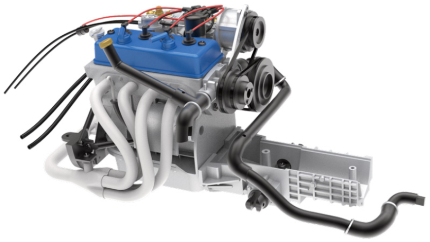
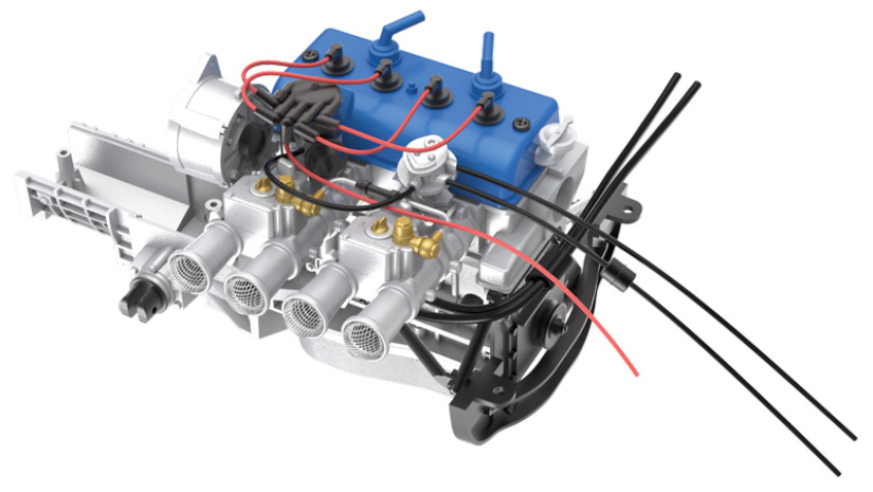
ASSEMBLY DIAGRAM
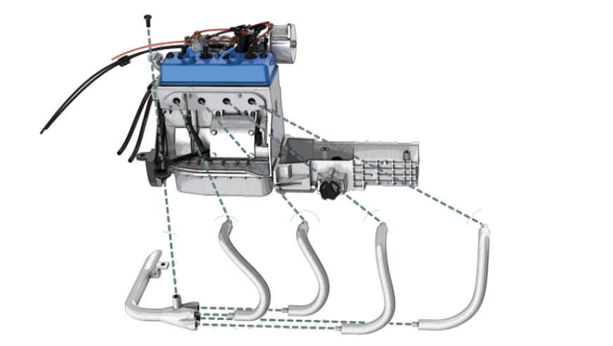
GENERAL VIEW
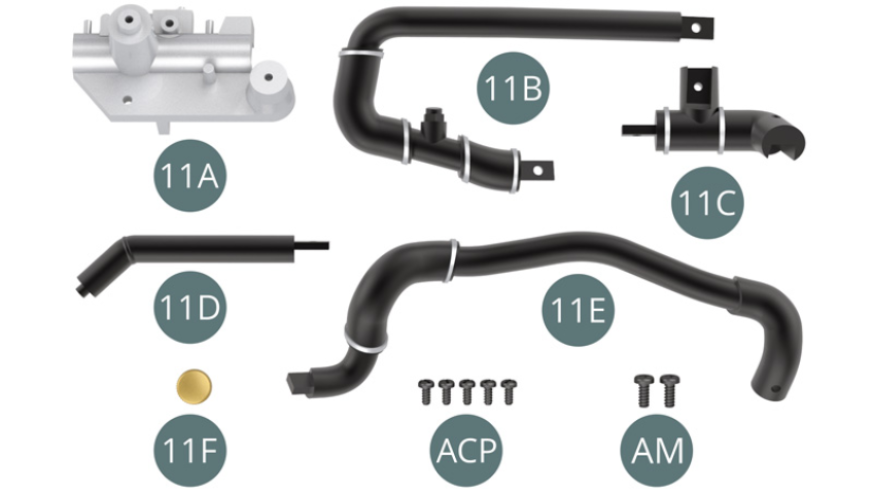
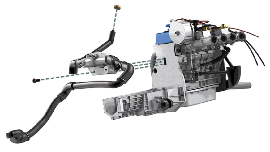
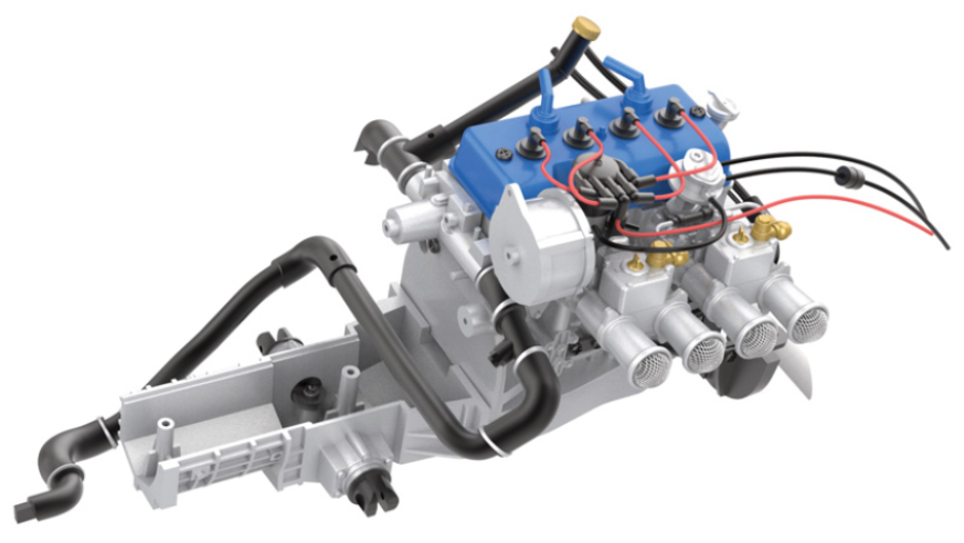
Kit 11 - Assembly of the front of the engine block and the cooling hoses
Parts of kit
- 11A Front of engine block
- 11B Cooling hose left
- 11C Hose elbow
- 11D Water filler spout
- 11E Cooling hose
- 11F Water hose cap
- Screw ACP M 1.4 x 3 mm (x 5)
- Screw AM M 1.7 x 4 mm (x 2)
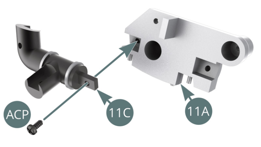
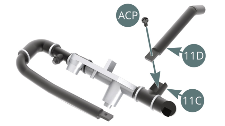
STEP 1
Position the hose elbow (11C) on the front of the engine block (11A) and secure with an ACP screw.
Position the left cooling hose (11B) on the front of the engine block (11A) and secure with an ACP screw.

STEP 2
Position the water filler spout (11D) onto the hose elbow (11C) and secure with an ACP screw.
Position the cooling hose (11E) onto the left cooling hose (11B) and secure with an ACP screw.

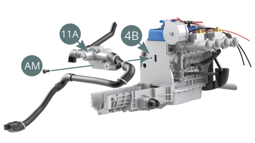
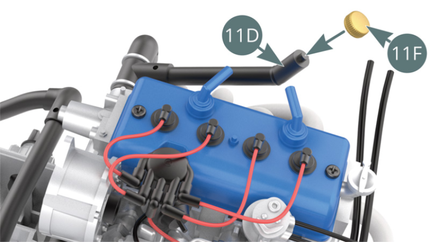
STEP 3
Position the front of the engine block (11A) on the right engine block (4B) and secure with an AM screw. Position the cap (11F) on the water filler spout (11D).
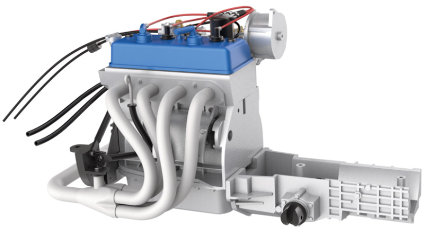
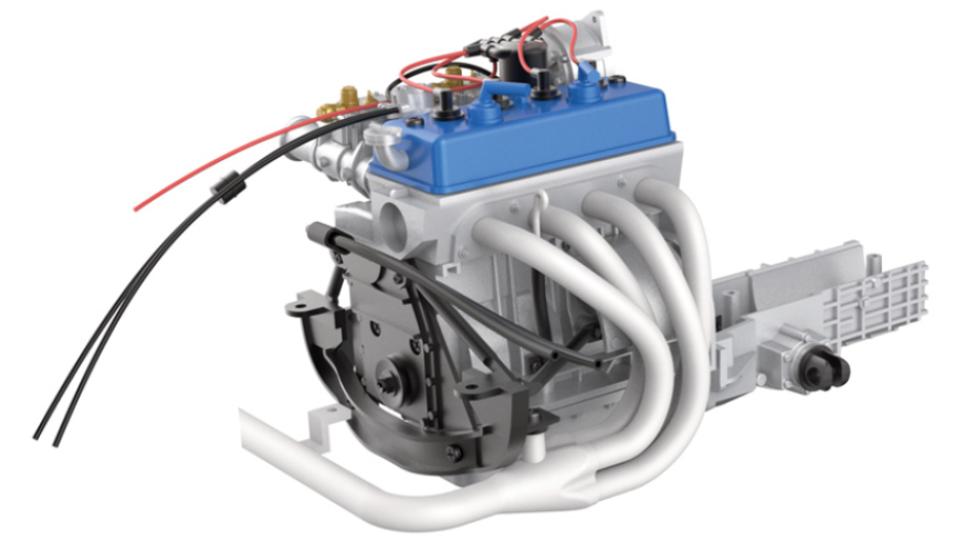
ASSEMBLY DIAGRAM
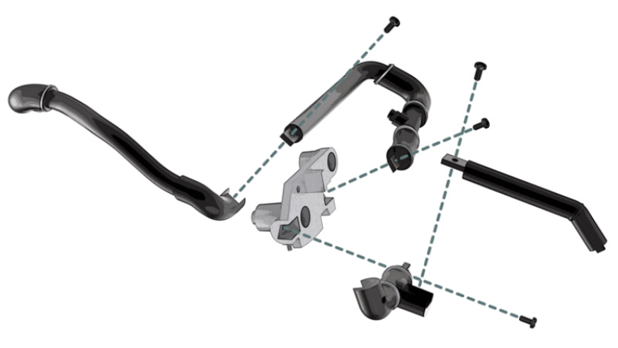
GENERAL VIEW
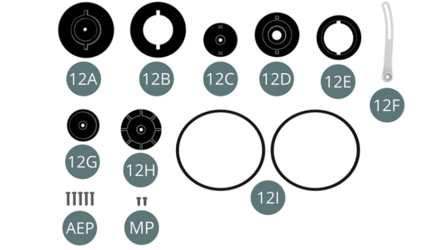
Kit 12 - Assembly and mounting of the timing belts and pulleys on the engine block
Parts of kit
- 12A Water pump pulley outer rim
- 12B Water pump pulley inner rim
- 12C Crankshaft pulley outer rim
- 12D Crankshaft pulley centre rim
- 12E Crankshaft pulley inner rim
- 12F Alternator adjustment arm
- 12G Alternator pulley outer rim
- 12H Alternator pulley inner rim
- 12I Timing belt (x 2)
- Screw AEP M 1.2 x 5 mm (x 5)
- Screw MP M 1.2 x 3 mm (x 2)
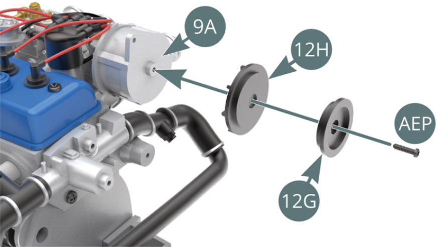
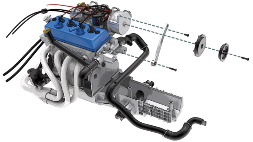
STEP 1
Position the inner (12H) and outer (12G) alternator pulley rims onto the alternator (9A) and secure with an AEP screw.
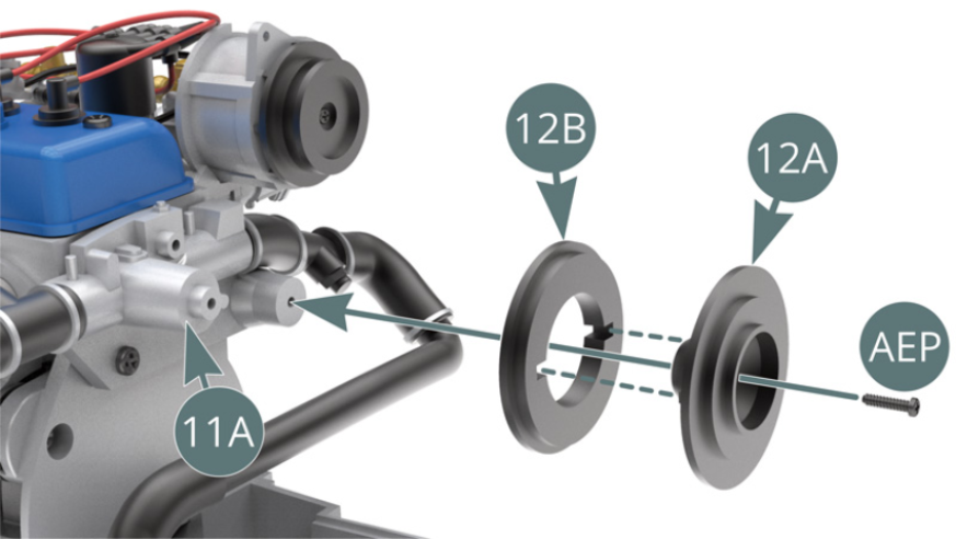
Position the inner (12B) and outer (12A) water pump pulley rims onto the engine block front pivot (11A) and secure with an AEP screw.
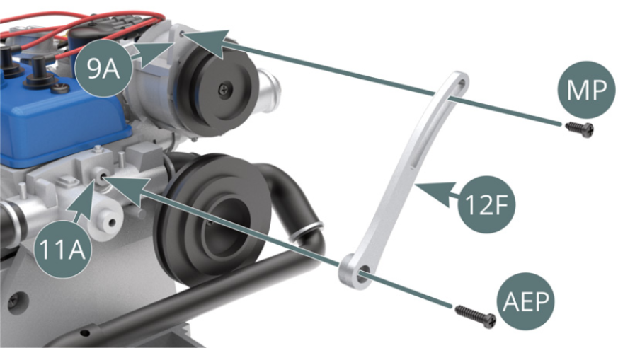
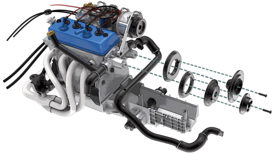
STEP 2
Position the lower end of the adjustment arm (12F) on the engine block front pin (11A) and the movable upper end on the eye above the alternator (9A) and secure with an AEP and MP screw respectively.
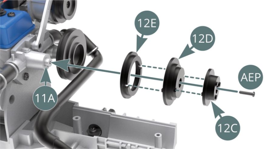
Position the inner (12E), middle (12D) and outer (12C) crankshaft pulley rims on the engine block front shaft (11A) and secure with an AEP.
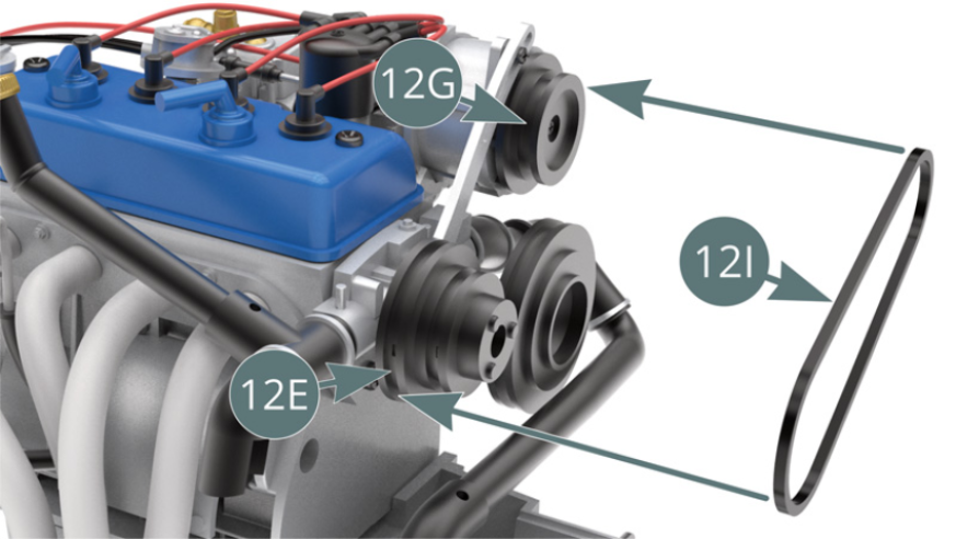
STEP 3
Position a timing belt (12I) on the inner crankshaft pulley rim (12E) and on the alternator pulley (12G).
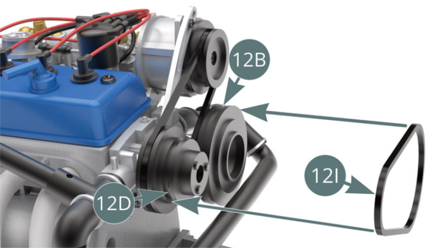
Position a timing belt (12I) on the centre crankshaft pulley rim (12D) and on the water pump pulley (12B).
ASSEMBLY DIAGRAM
GENERAL VIEW