English
 français
 Deutsch
 español
 italiano
 português


Box 4
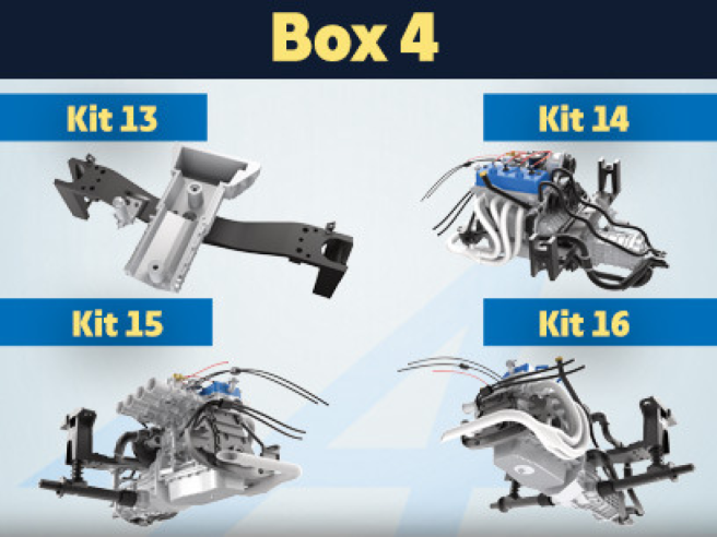
Kit 13 - Assembly of the rear suspension cross beam and mounting of the top of the gearbox housing
Parts of kit
- 13A Rear suspension cross beam
- 13B Brake master cylinder
- 13C Left rear brake line support
- 13D Right rear brake line support
- Screw MM M 1.2 x 3 mm (x 3)
- Screw AFM M 2.3 x 4 mm (x 2)
- Screw QM M 1.4 x 3 mm (x 2)

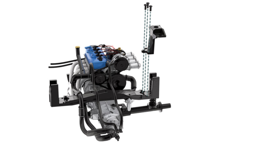
STEP 1
Position the left rear brake line support (13C) on the rear suspension cross beam (13A) and secure it with an MM screw.
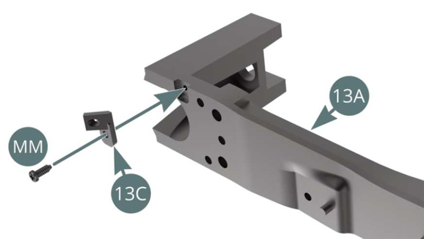
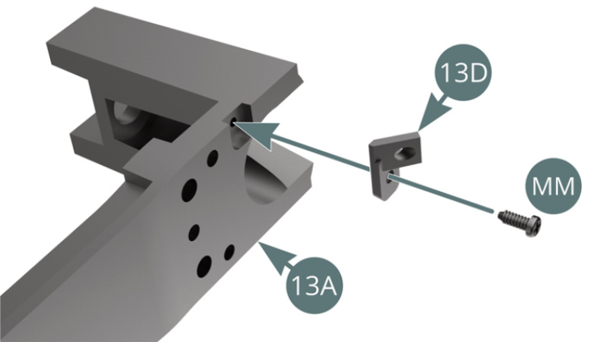
Position the right rear brake line support (13D) on the rear suspension cross beam (13A) and secure it with an MM screw.
STEP 2
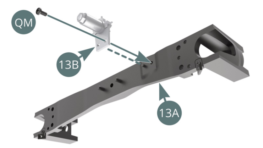
Position the brake master cylinder (13B) on the rear suspension cross beam (13A) and secure with a QM screw.
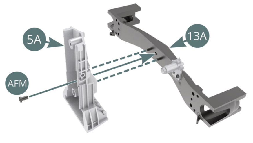
Position the gearbox top (5A) on the rear suspension cross beam (13A) and secure with an AFM screw.
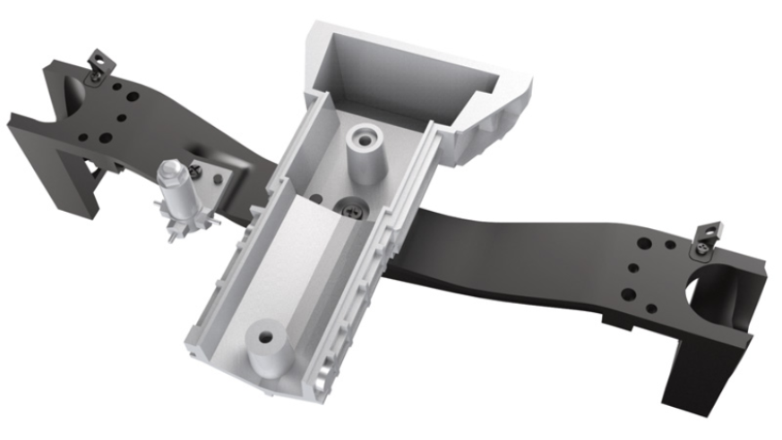
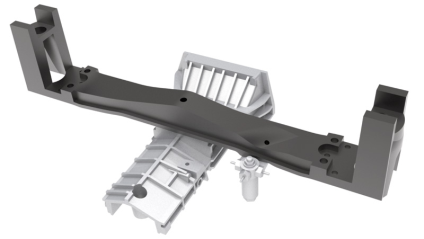
ASSEMBLY DIAGRAM
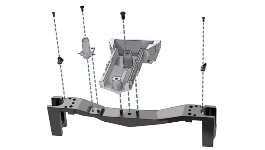
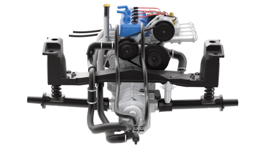
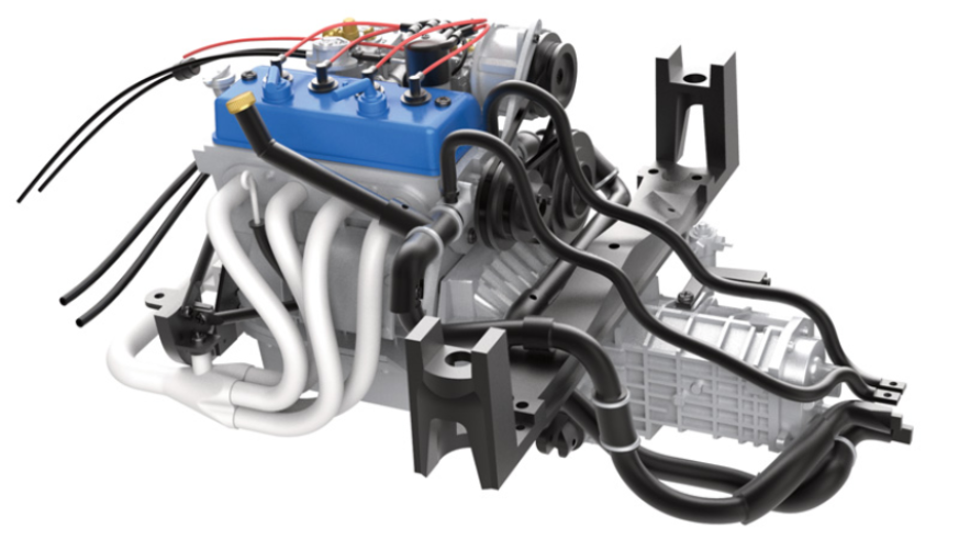
GENERAL VIEW
Kit 14 - Assembly of water pipelines, water hoses and gearbox housing, mounting of the gear selector
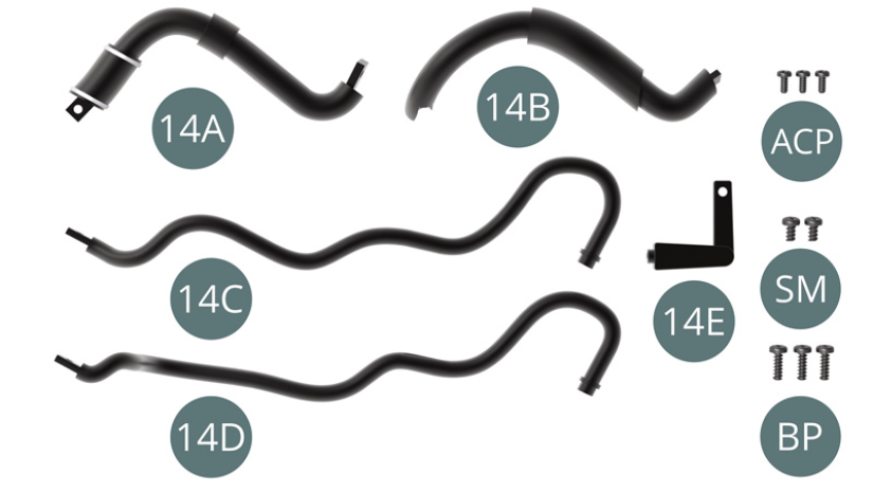
Parts of kit
- 14A Water pipeline
- 14B Water pipeline
- 14C Left water hose
- 14D Right water hose
- 14E Gear selector rod
- Screw ACP M 1.4 x 3 mm (x 3)
- Screw SM M 1.7 x 3 mm (x 2)
- Screw BP M 1.7 x 5 mm (x 3)
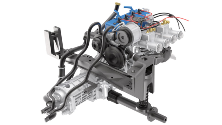
STEP 1
Position the rear gearbox cover (5C) onto the lower transmission housing (4E).

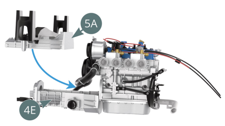
Position the top of the gearbox cover (5A) onto the lower transmission housing (4E).
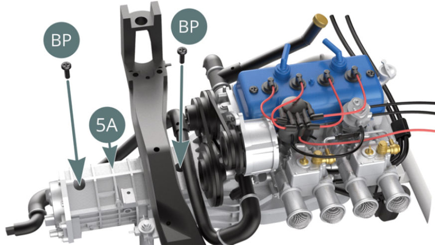
STEP 2
Attach the top of the gearbox housing (5A) to the bottom of the transmission housing (4E) with two BP screws.
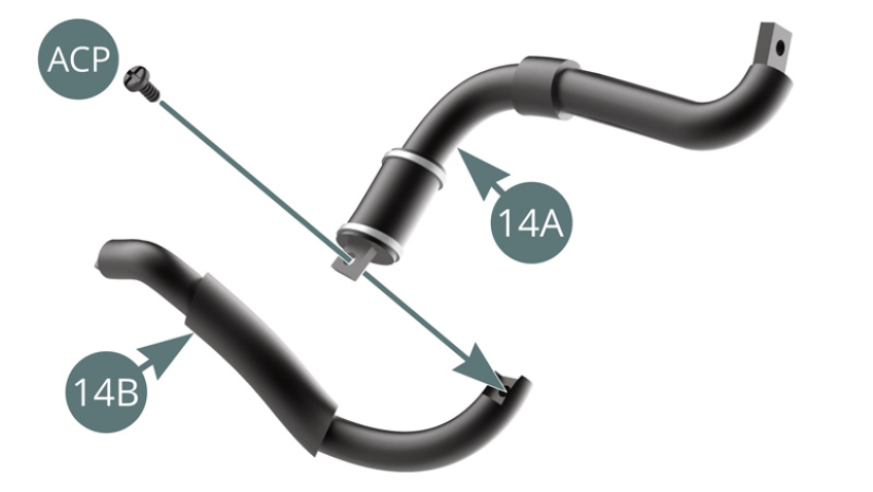
Connect the water pipelines (14A & 14B), and then secure them with a PCR screw.
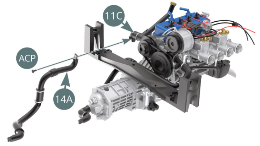
STEP 3
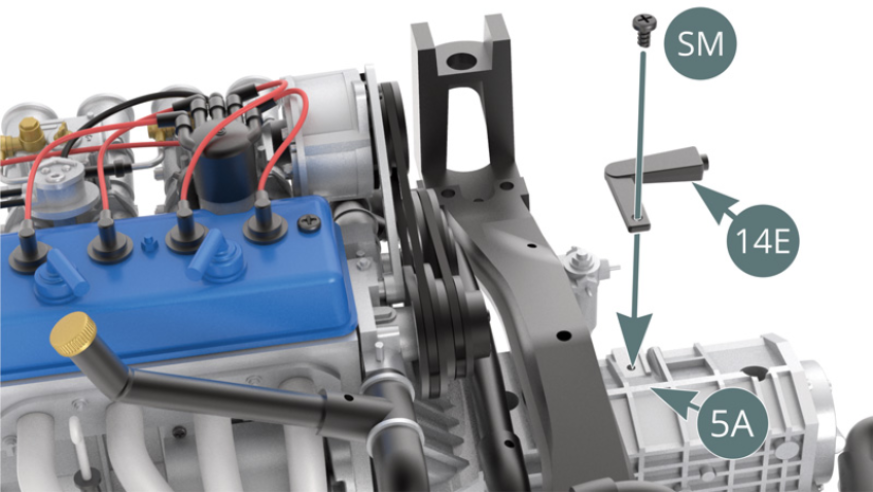
Position the water pipeline (14A) on the hose elbow (11C) and secure with an ACP screw. Position the gear selector (14E) onto the top of the gearbox housing (5A) and secure with an SM screw.
STEP 4
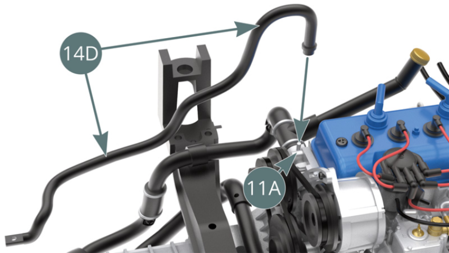
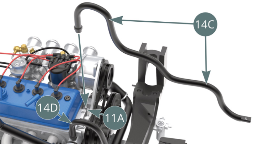
Position the right water hose (14D) onto the right nozzle on the front of the engine block (11A). Posi-tion the left water hose (14C) onto the left nozzle on the front of the engine block (11A).
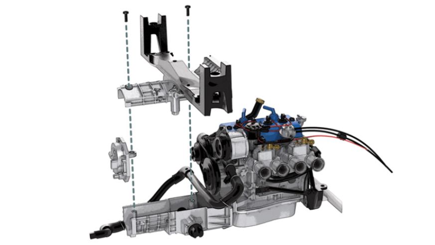
ASSEMBLY DIAGRAM

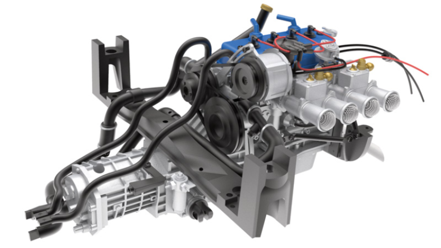
GENERAL VIEW
Kit 15 - Assembly and installation of the left rear suspension and transmission shaft
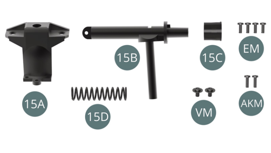
Parts of kit
- 15A Left suspension cup
- 15B Left transmission shaft with shock absorber
- 15C Transmission shaft bellows
- 15D Suspension spring
- Screw VM M 2.3 x 4 x 6 mm (x 2)
- Screw EM M 2.0 x 5 mm (x 4)
- Screw AKM M 2.0 x 6 mm (x 2)
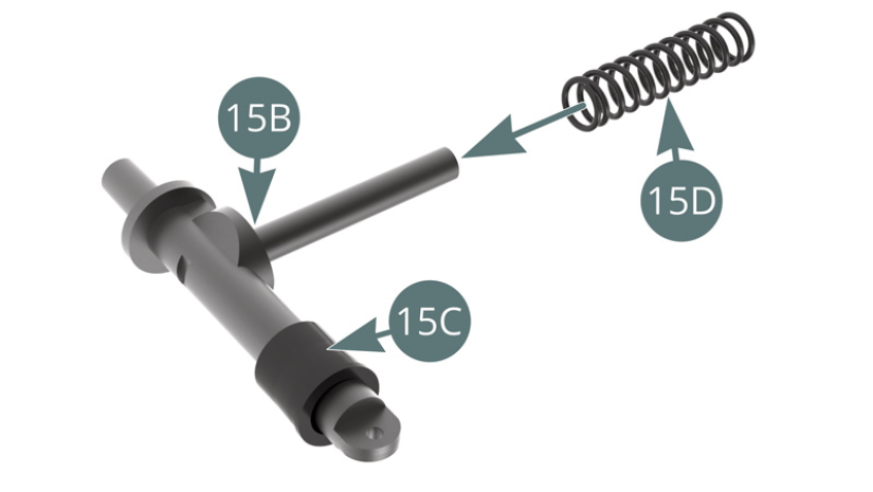
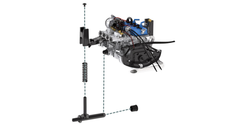
STEP 1
Position the bellows (15C) on the left transmission shaft (15B). Position the suspension spring (15D) onto the left transmission shock absorber (15B).
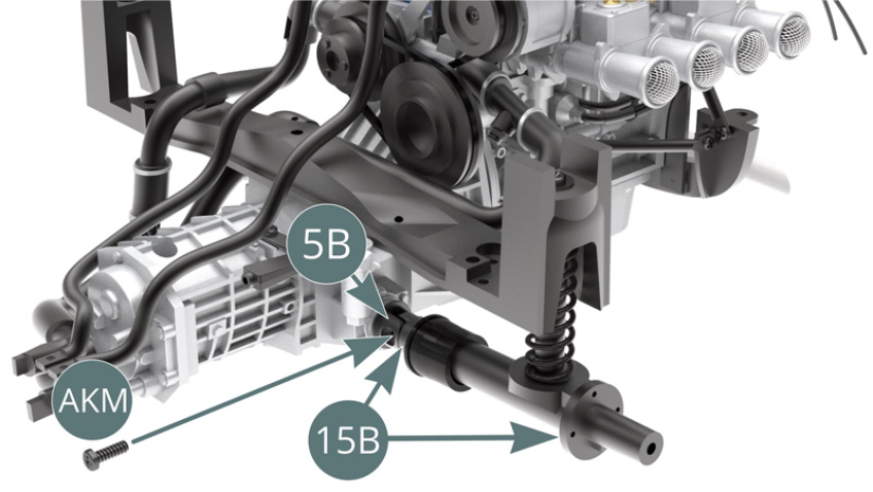
Position the left transmission shock absorber (15B) on the transmission joint (5B) and the rear sus-pension beam (13A) and secure it to the latter with a VM screw.
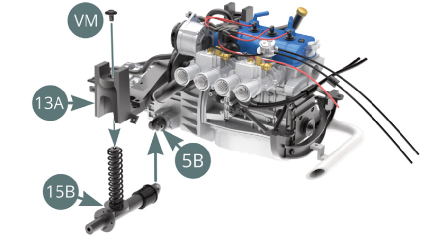
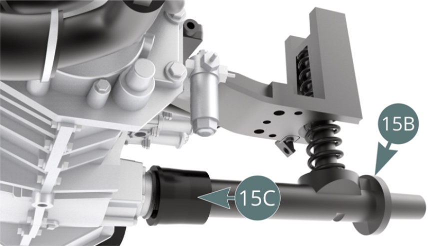
STEP 2
Fix the left transmission shaft (15B) to the transmission joint (5B) with an AKM screw, then slide the bellows (15C) over the transmission joint (5B) - see illustrations opposite and below.
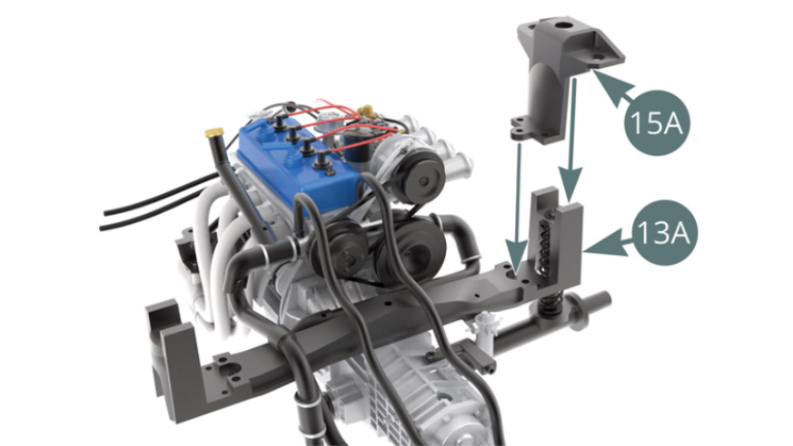
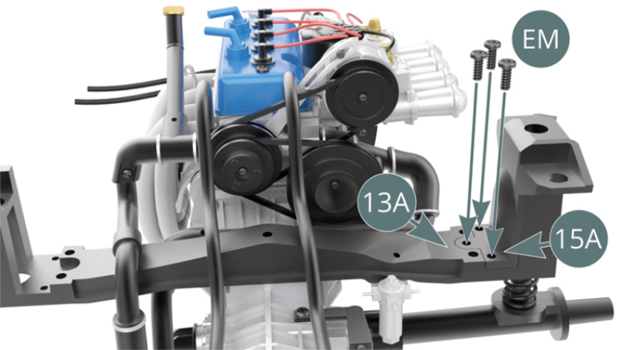
STEP 3
Position the left suspension cup (15A) on the rear suspension cross beam (13A) and secure with three EM screws ( pictured opposite and below).
ASSEMBLY DIAGRAM
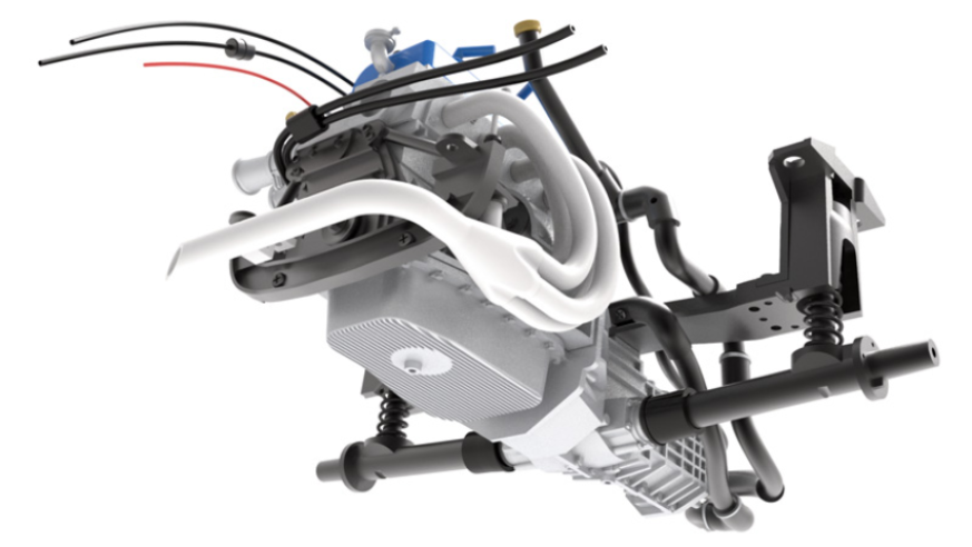
GENERAL VIEW
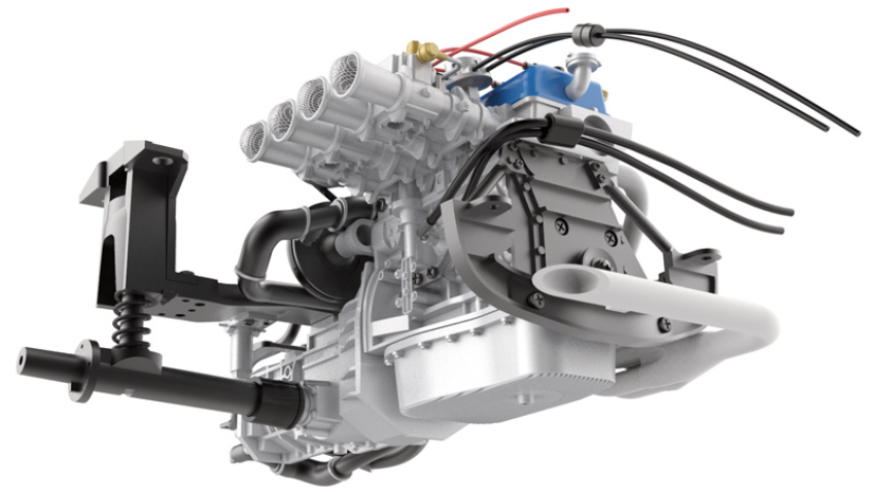
Kit 16 - Assembling and installation the right rear suspension and transmission shaft
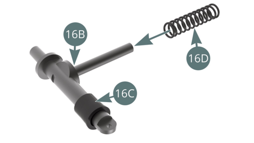
Parts of kit
- 16A Right suspension cup
- 16B Right transmission shaft with shock absorber
- 16C Transmission shaft bellows
- 16D Suspension spring
- Screw VM M 2.3 x 4 x 6 mm (x 2)
- Screw EM M 2.0 x 5 mm (x 4)
- Screw AKM M 2.0 x 6 mm (x 2)

STEP 1
Position the bellows (16C) on the right transmission shaft (16B). Position the suspension spring (16D) onto the right transmission shock absorber (16B).
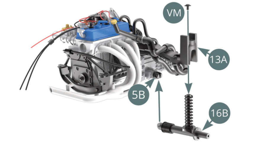
Position the left transmission shock absorber (16B) on the transmission joint (5B) and the rear sus-pension beam (13A) and secure it to the latter with a VM screw.
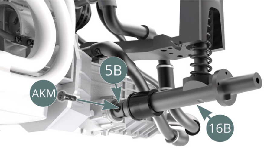
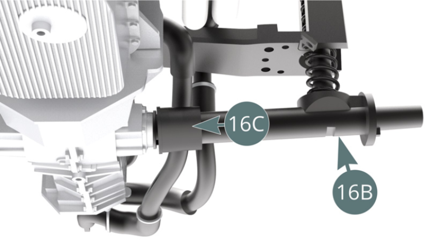
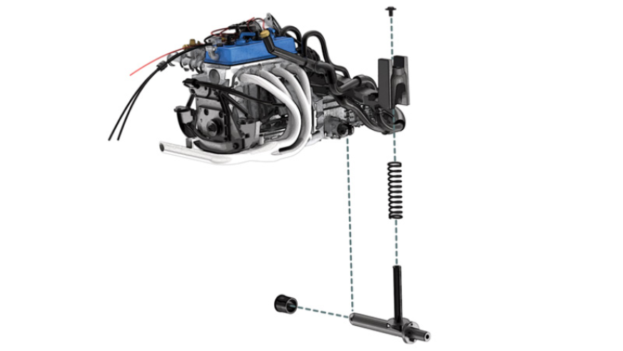
STEP 2
Fix the right transmission shaft (16B) to the transmission joint (5B) with an AKM screw, then slide the bellows (16C) over the transmission joint (5B) - see illustrations.
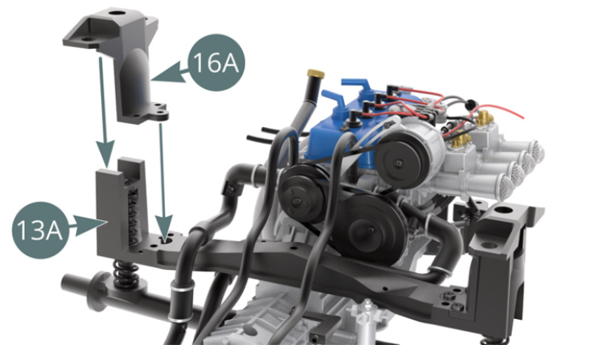
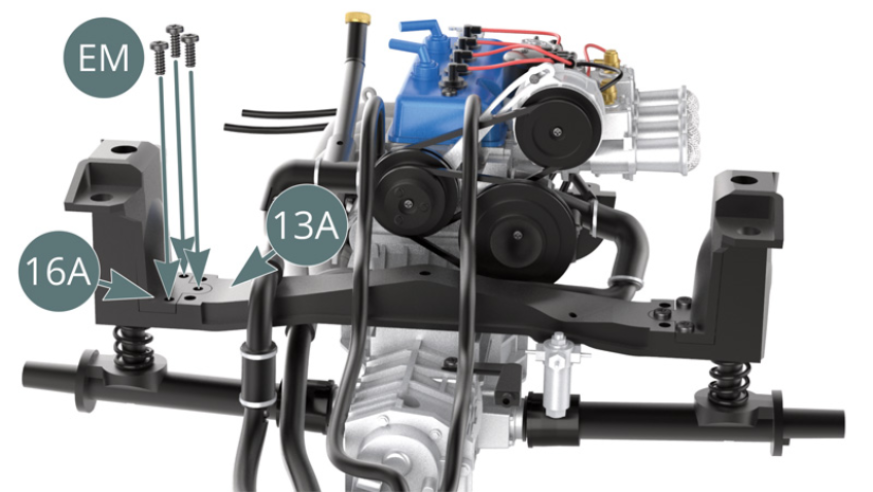
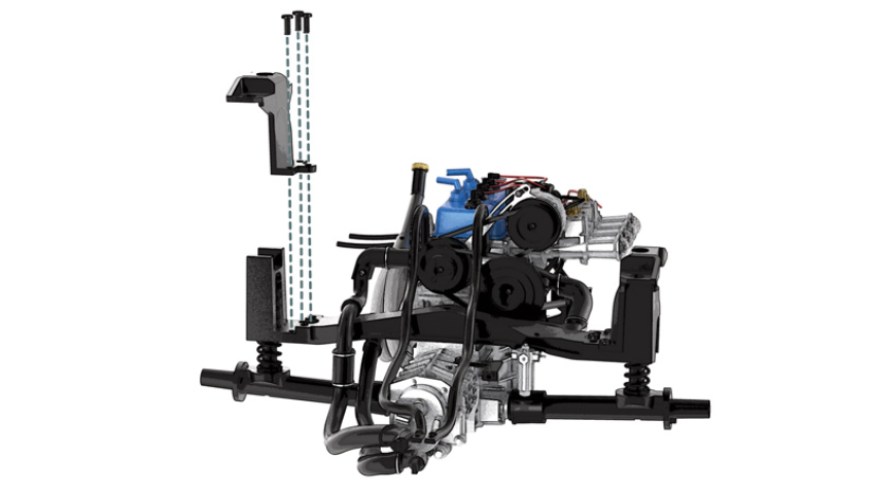
STEP 3
Position the right suspension cup (16A) on the rear suspension cross beam (13A) and secure with three EM screws ( pictured opposite and below).
ASSEMBLY DIAGRAM
GENERAL VIEW