English
 français
 Deutsch
 español
 italiano
 português


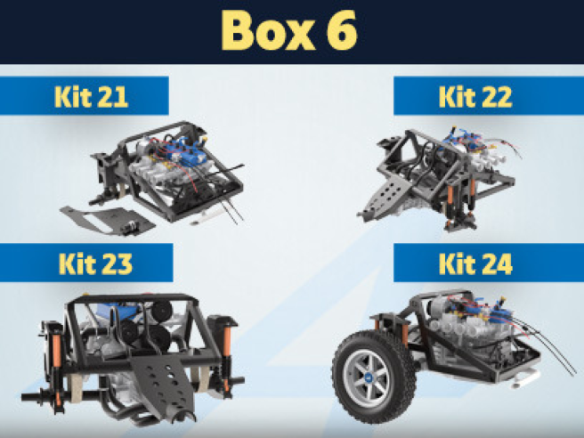
Box 6
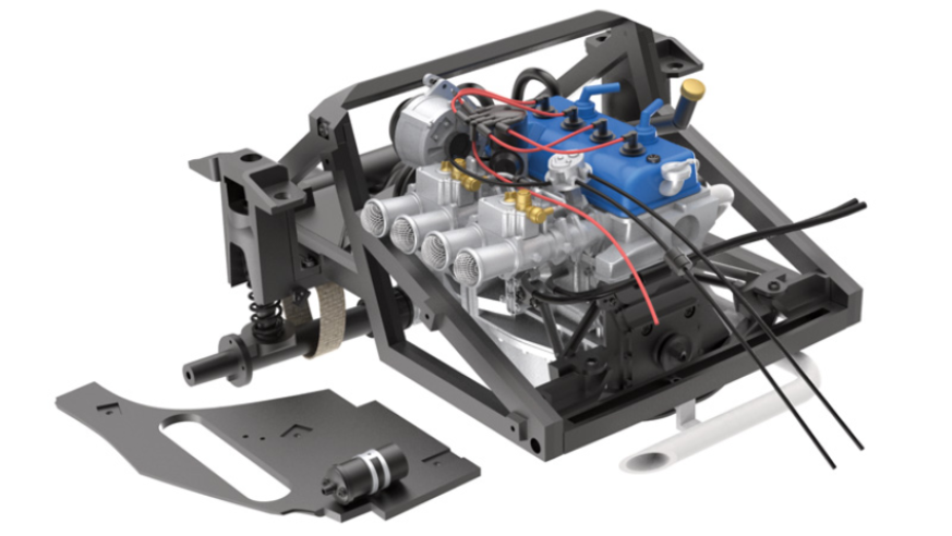
Kit 21 - Fixing the suspension retaining straps and pre-assembling of the left engine compartment panel
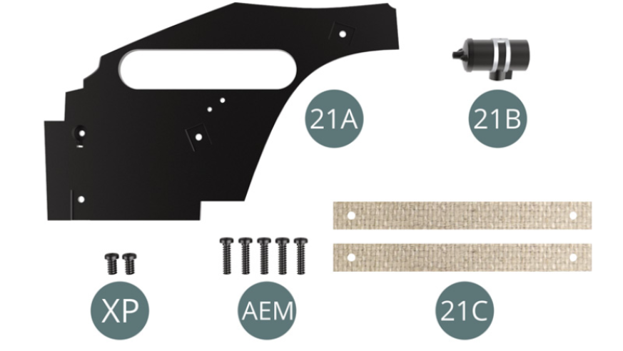
Parts of kit
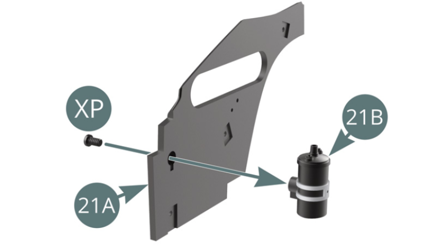
- 21A Left engine compartment panel
- 21B Ignition coil
- 21C Retaining strap (x 2)
- Screw XP M 2.3 x 4 mm (x 2)
- Screw AEM M 2.0 x 8 mm (x 5)
STEP 1
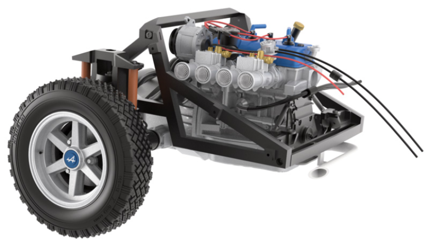
Position the ignition coil (21B) on the left side of the engine compartment (21A) and secure it with an XP screw.
STEP 2
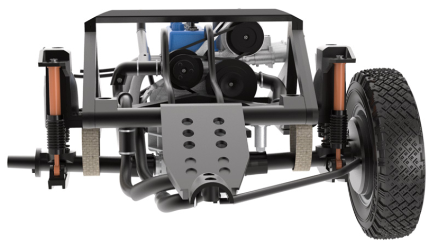
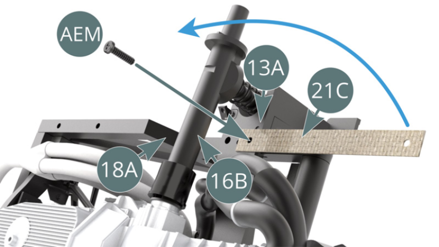
Position one end of a retaining strap (21C) over the rear suspension cross beam (13A) and secure it with an AEM screw through the right frame (18A).
STEP 3
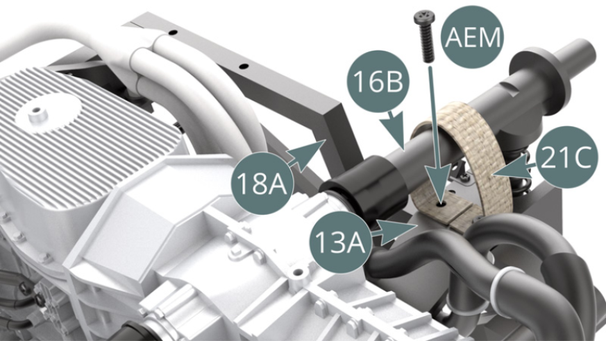
Wrap the other end of the strap (21C) around the right transmission shaft (16B) and secure it with another AEM screw as before (previous and above illustrations).
STEP 4
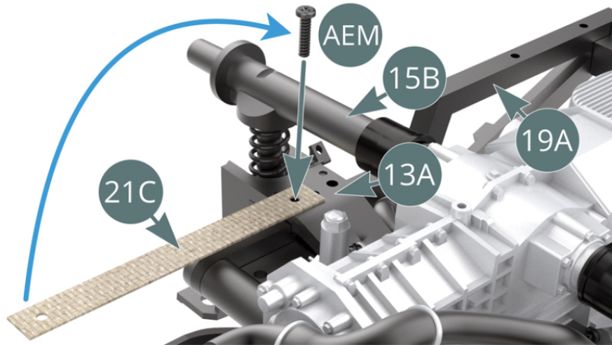
Position one end of a retaining strap (21C) over the rear suspension cross beam (13A) and secure with an AEM screw across the left frame (19A).
STEP 5
Wrap the other end of the strap (21C) around the left transmission shaft (15B) and secure it with another AEM screw as before (previous and above illustrations)
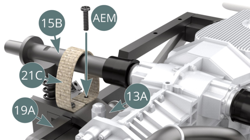
STEP 6
The retaining straps are attached to the rear suspension.
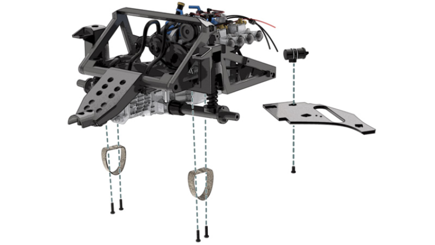
ASSEMBLY DIAGRAM
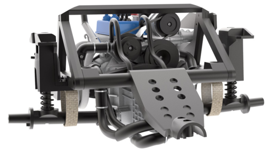
GENERAL VIEW
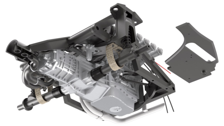
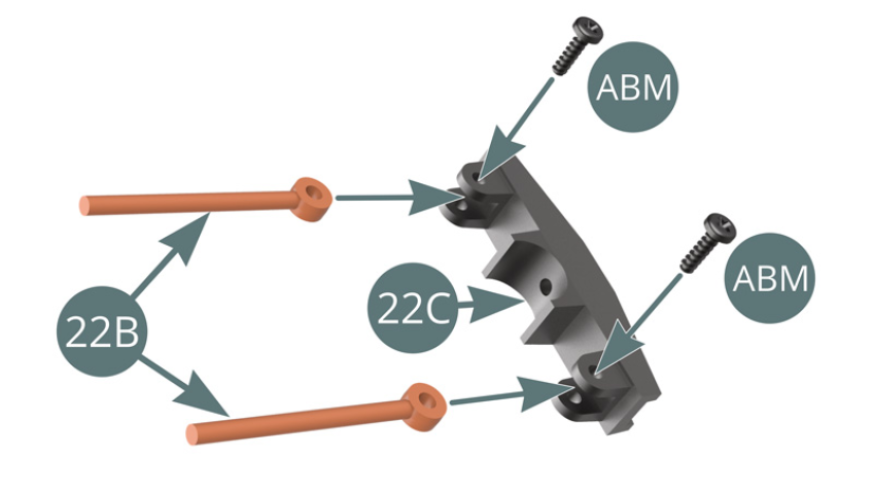
Kit 22 - Left rear shock absorber assembly and mounting on the suspension
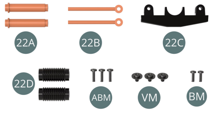
Parts of kit
- 22A Shock cylinder (x 2)
- 22B Shock piston (x 2)
- 22C Bracket
- 22D Dust boot (x 2)
- ABM
- Screw ABM M 1.7 x 6 mm (x 3)
- Screw VM M 2.3 x 4 x 6 mm (x 3)
- Screw BM M 1.7 x 5 mm (x 2)
STEP 1
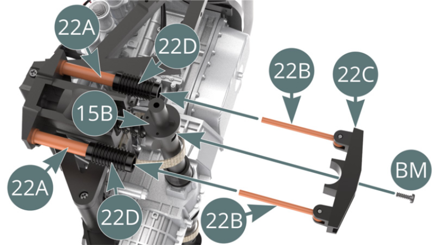
Position the two shock cylinders (22A) on the left suspension cup (15A) and secure each with a VM screw.
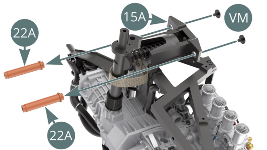
Position the two dust boots (22D) onto the shock cylinders (22A).
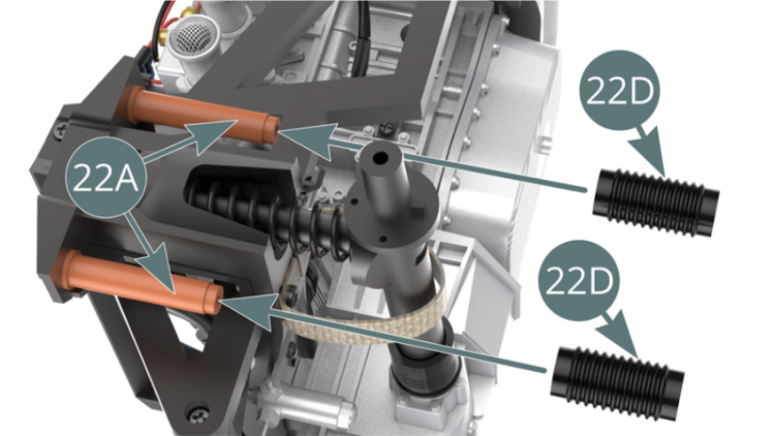
STEP 2
Position both shock pistons (22B) on the bracket (22C) and secure with two ABM screws.
Simultaneously insert both shock pistons (22B) into both shock cylinders (22A) through the two dust boots (22D). Fix the bracket (22C) to the left transmission shaft (15B) with a BM screw.
ASSEMBLY DIAGRAM
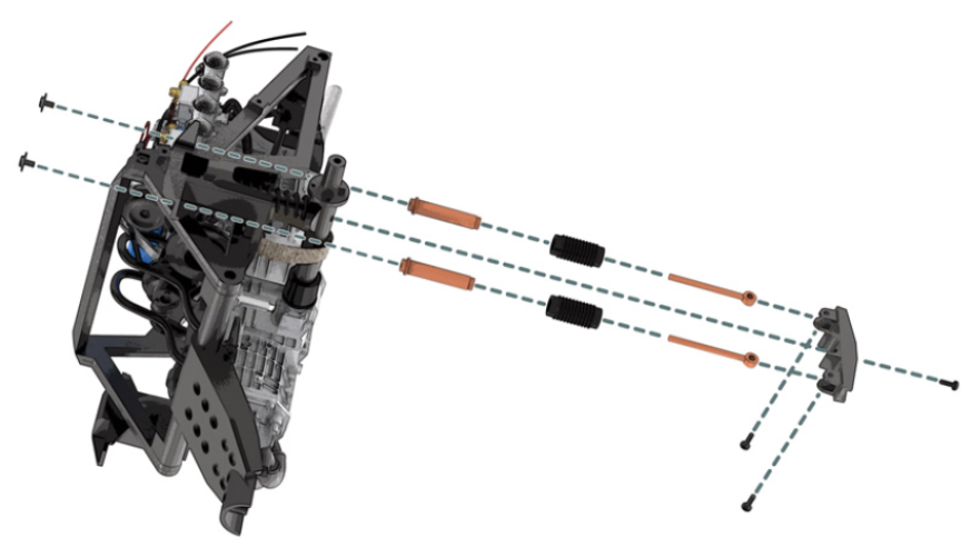
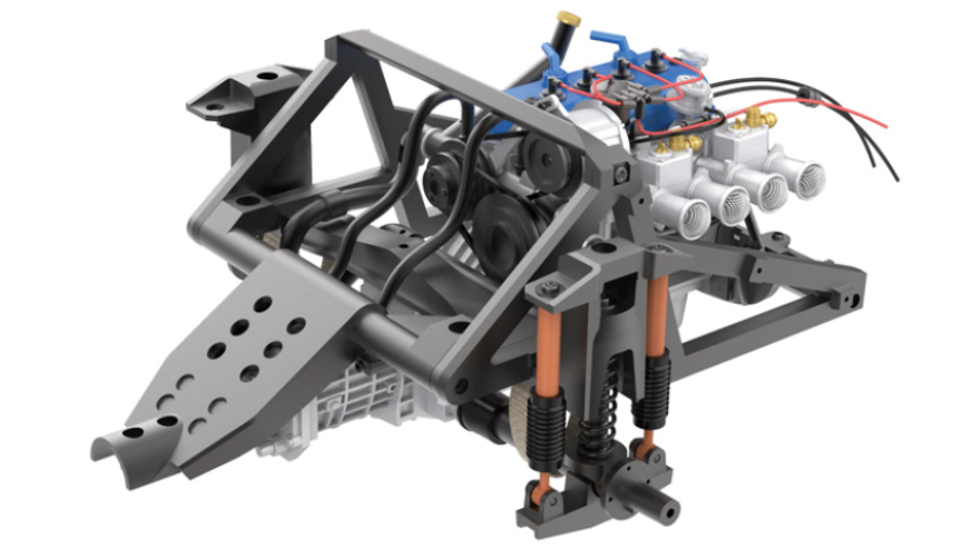
GENERAL VIEW
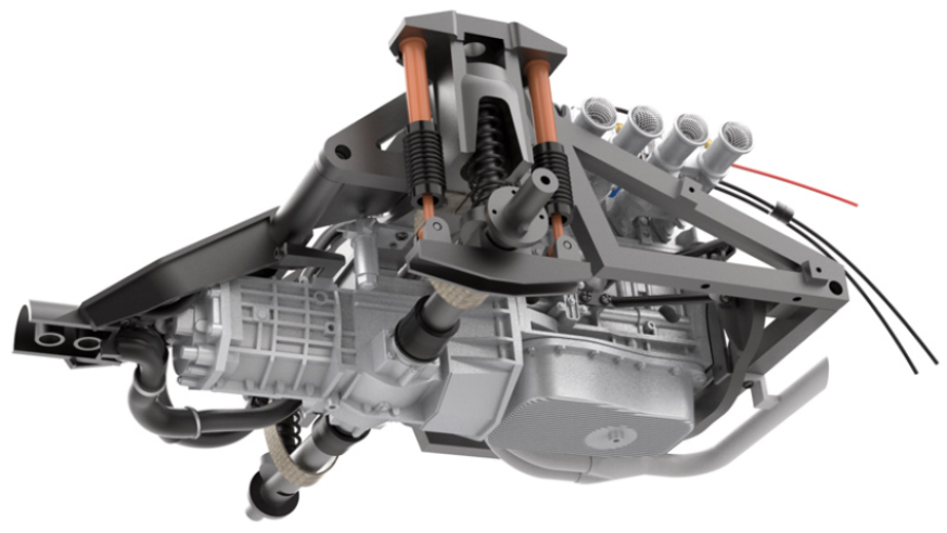
Kit 23 - Right rear shock absorber assembly and mounting on the suspension
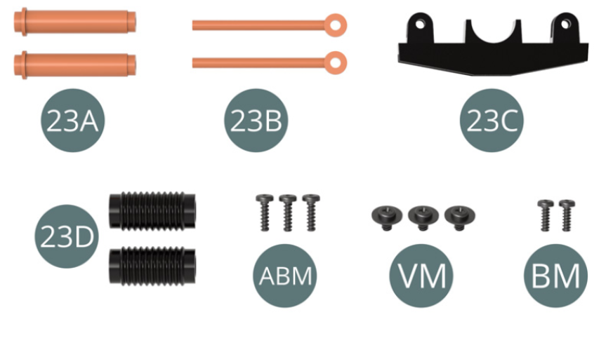
Parts of kit
- 23A Shock cylinder (x 2)
- 23B Shock piston (x 2)
- 23C Bracket
- 23D Dust boot (x 2)
- Screw ABM M 1.7 x 6 mm (x 3)
- Screw VM M 2.3 x 4 x 6 mm (x 3)
- Screw BM M 1.7 x 5 mm (x 2)
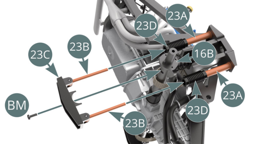
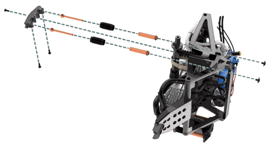
STEP 1
Position the two shock cylinders (23A) on the right suspension cup (16A) and secure each with a VM screw.
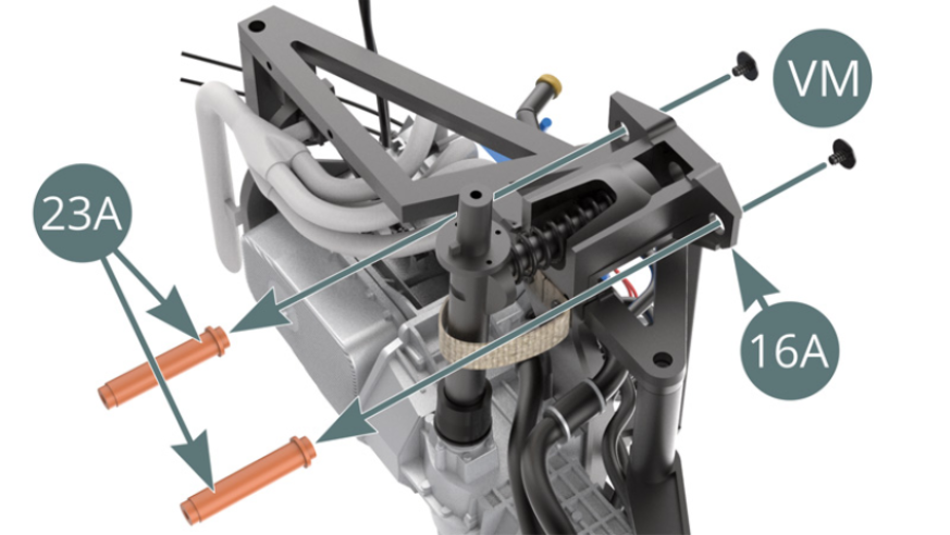
Position the two dust boots (23D) onto the shock cylinders (23A).
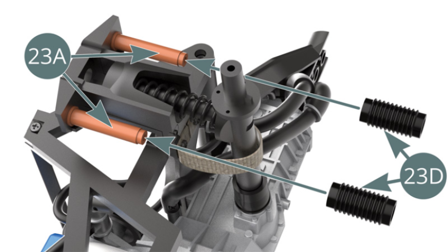
STEP 2
Position the two shock pistons (23B) on the bracket (23C) and secure with two ABM screws.

At the same time, insert both damper pistons (23B) into both damper cylinders (23A) by passing them through the two dust boots (23D). Fix the bracket (23C) to the right transmission shaft (16B) with a BM screw.
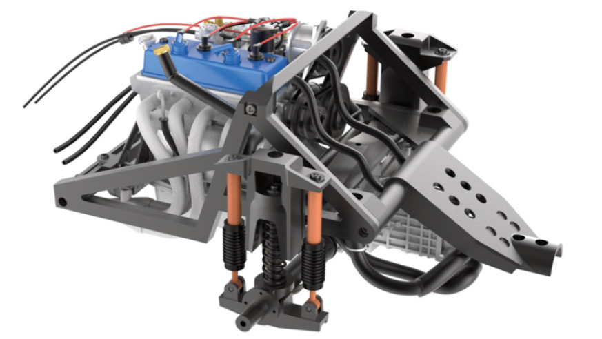
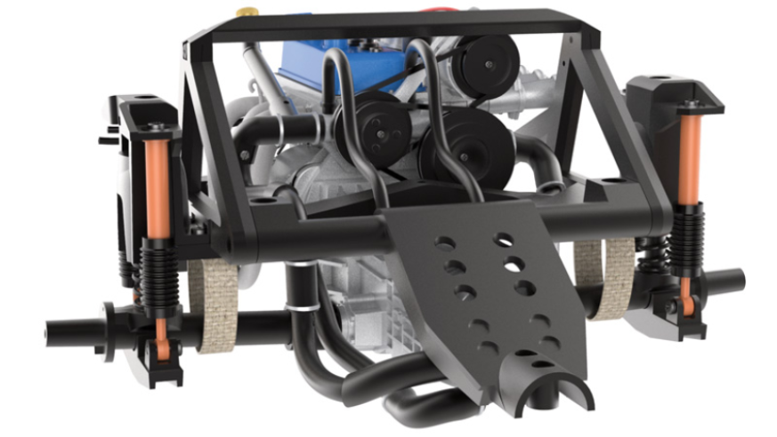
ASSEMBLY DIAGRAM
GENERAL VIEW
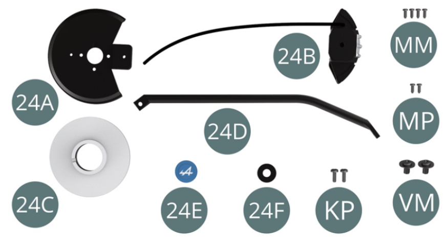
Kit 24 - Assembly of the left rear brake disc, support arm, wheel and installation on the drive shaft
Parts of kit
- 24A Dust cover
- 24B Brake caliper and hose
- 24C Brake disc
- 24D Support arm
- 24E Hub cap
- 24F Washer
- Screw KP M 1.4 x 4 mm (x 2)
- Screw MM M 1.2 x 3 mm (x 4)
- Screw MP M 1.2 x 3 mm (x 2)
- Screw VM M 2.3 x 4 x 6 mm (x 2)
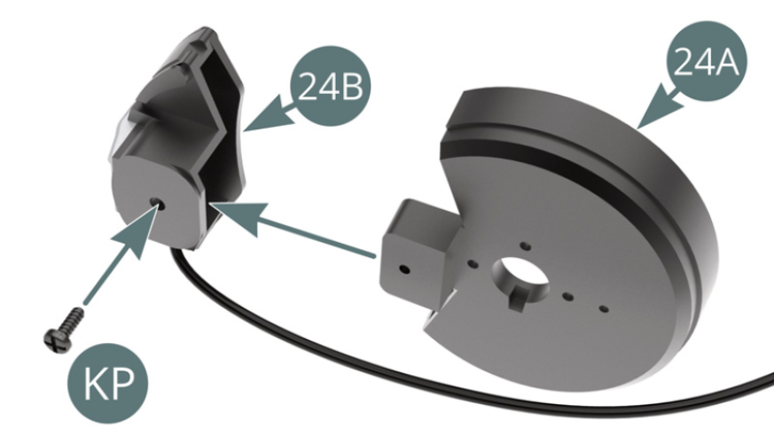
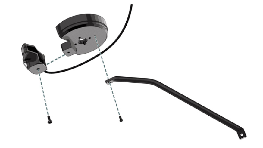
STEP 1
Position the dust cover (24A) onto the brake caliper (24B) and secure with a KP screw.
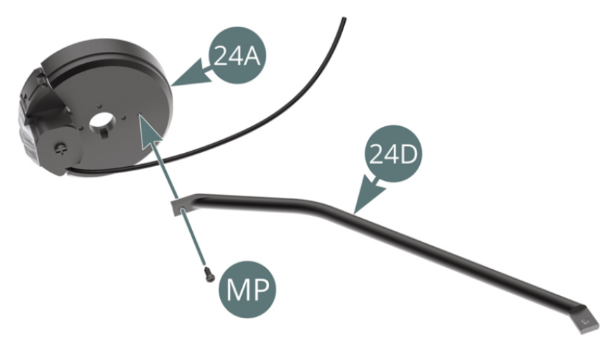
Position the support arm (24D) on the dust cover (24A) and secure with a MP screw ( allow a small amount of play at the fixing point).
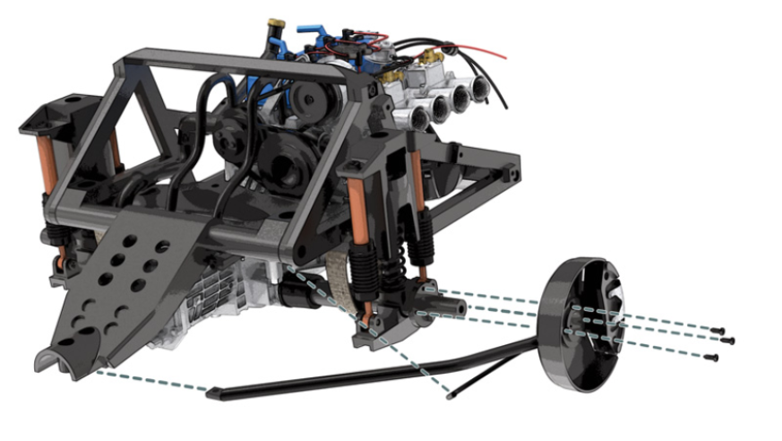
STEP 2
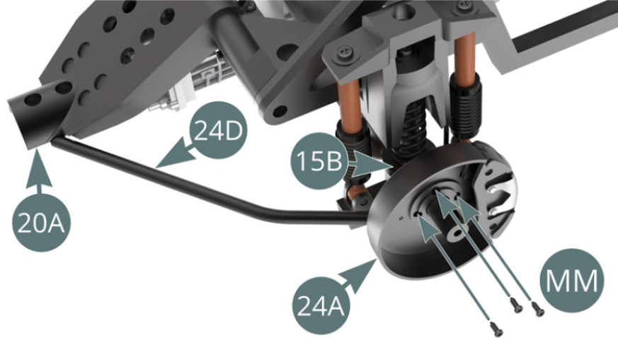
Position the dust cover (24A) onto the left transmission shaft (15B) - observe the correct alignment indicated by the red dashes.
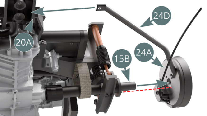
Position the end of the support arm (24D) onto the main frame (20A), then secure the dust cover (24A) with three MM screws ( pictured above and opposite)
STEP 3
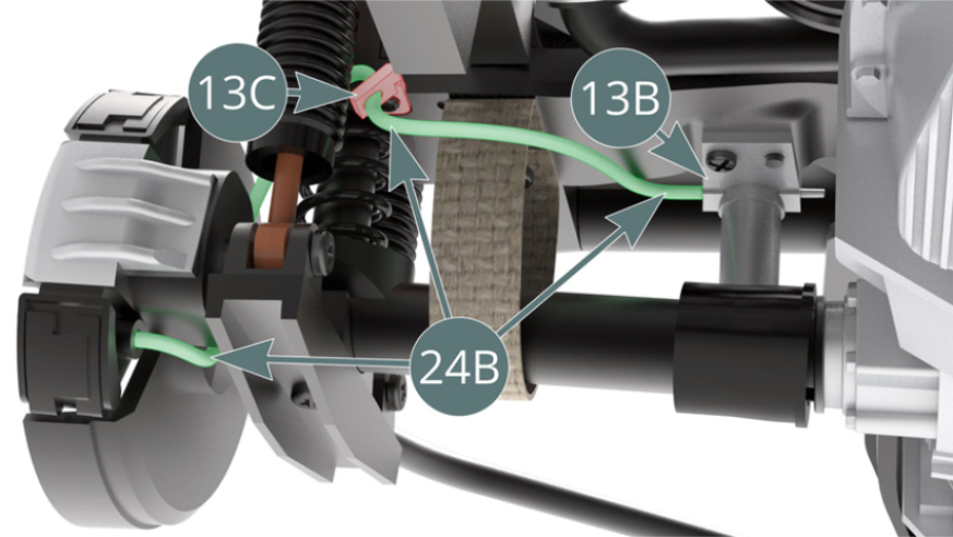
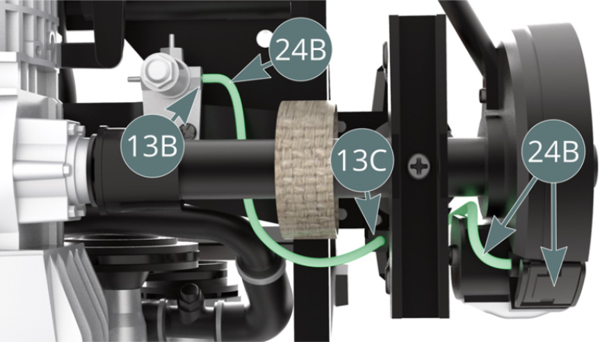
Guide the brake hose (24B) - highlighted in green - through the left rear brake line support (13C) and attach it to the master cylinder (13B) - shown above.
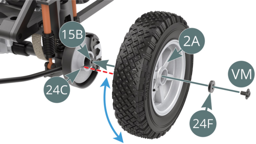
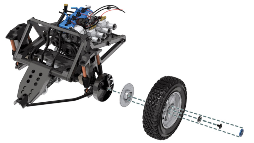
STEP 4
Position the brake disc (24C) on the left transmission shaft (15B) while engaging the brake caliper (24B) and dust cover (24A).
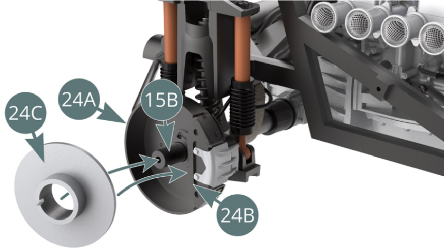
Position the pre-assembled wheel on the left transmission shaft (15B) via the outer wheel rim (2A). Turn it back and forth to engage it in the notch located on the brake disc (24C) - red dotted line - then secure it with a VM screw previously passed through the washer (24F).
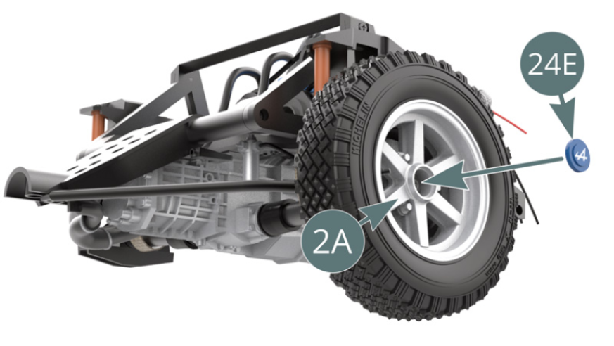
STEP 5
Position the hub cap (24E) onto the outer wheel rim (2A).
ASSEMBLY DIAGRAM
GENERAL VIEW