English
 français
 Deutsch
 español
 italiano
 português


Box 7
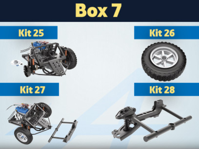
Kit 25 - Assembly of the right rear brake disc, support arm and wheel and installation on the drive shaft
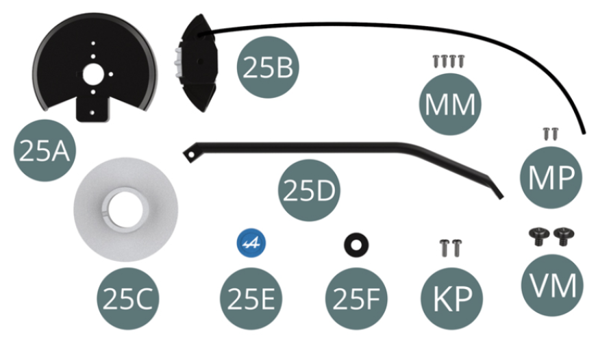
Parts of kit
- 25A Dust cover
- 25B Brake caliper and hose
- 25C Brake disc
- 25D Support arm
- 25E Hub cover
- 25F Washer
- Screw KP M 1.4 x 4 mm (x 2)
- Screw MM M 1.2 x 3 mm (x 4)
- Screw MP M 1.2 x 3 mm (x 2)
- Screw VM M 2.3 x 4 x 6 mm (x 2)
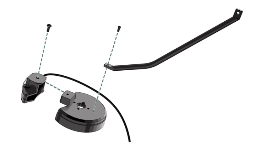
STEP 1
Position the dust cover (25A) on the brake caliper (25B) and secure with a KP screw.
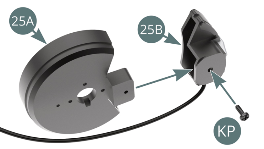
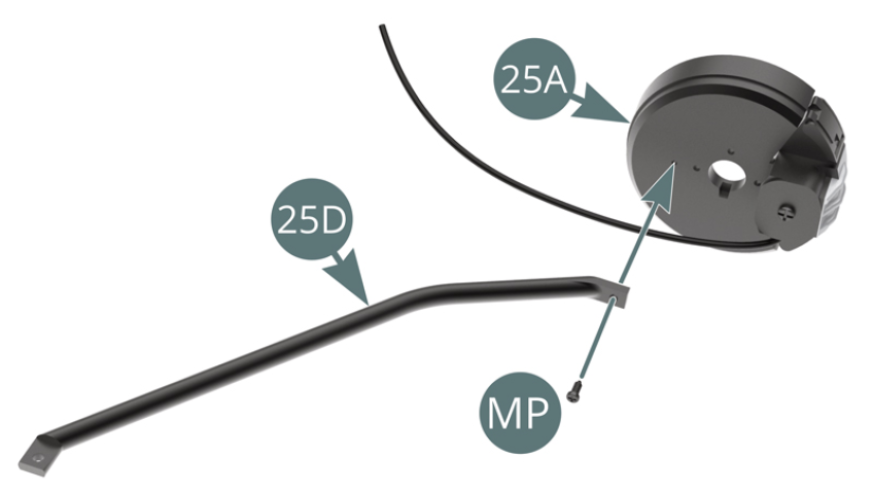
Position the support arm (25D) on the dust cover (25A) and fix it with a MP screw (leave a little play in the fixing area).
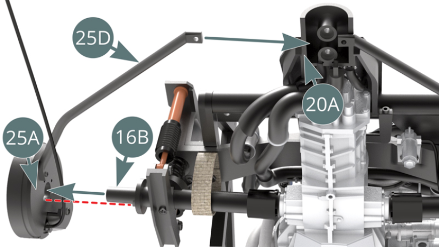
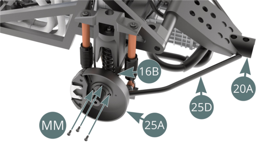
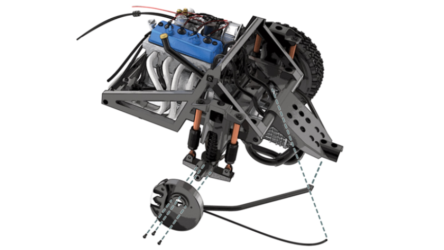
STEP 2
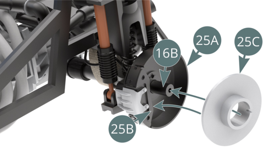
Position the dust cover (25A) onto the right hand drive shaft (16B) - observe the correct alignment indicated by the red dashes. Position the end of the support arm (25D) on the main frame (20A), then secure the dust cover (25A) with three MM screws (shown above).
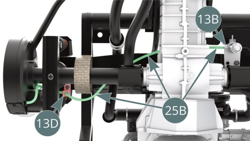
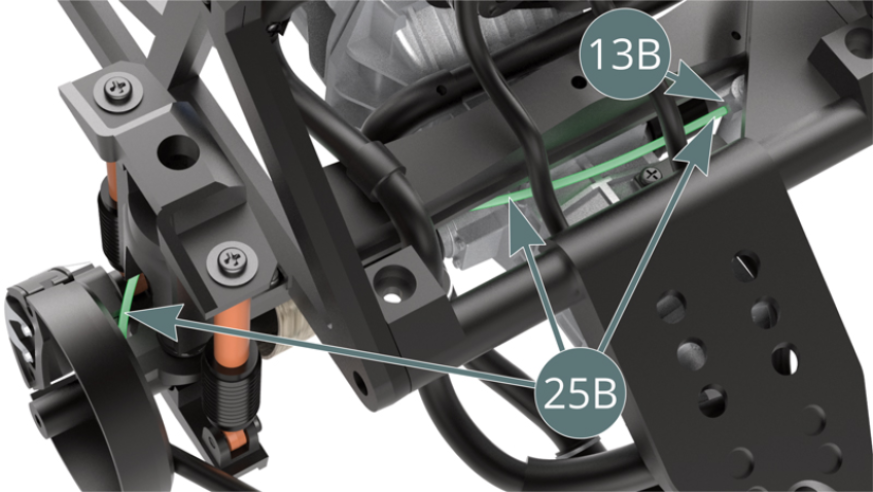
STEP 3
Route the brake hose (25B) - highlighted in green - through the right rear brake line support (13D) and attach it to the master cylinder (13B) (shown above).
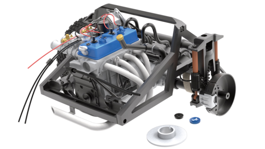
ASSEMBLY DIAGRAM
GENERAL VIEW
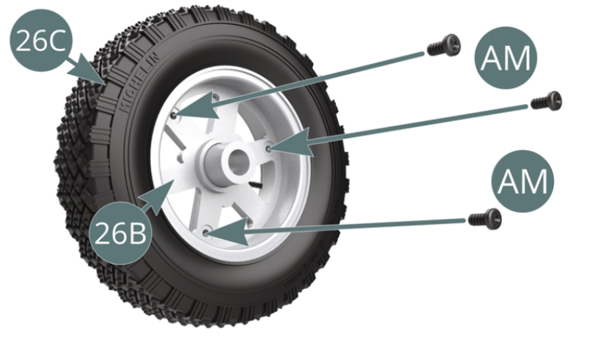
Kit 26 - Wheel assembly
Parts of kit
- 26A Outer wheel rim
- 26B Inner wheel rim
- 26C Tyre
- Screw AM M 1.7 x 4 mm (x 4)

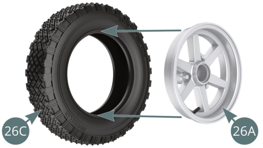
STEP 1
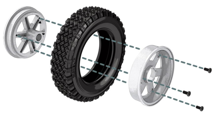
Position the outer wheel rim (26A) into the tyre (26C).
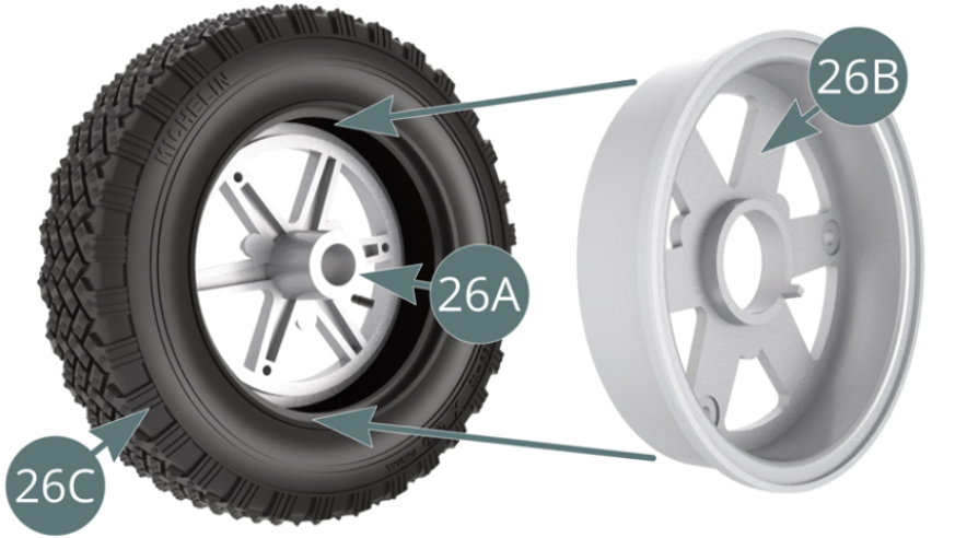
STEP 2
Position the inner wheel rim (26B) in the tyre (26C), aligning it with the outer rim (26A) and secure with three AM screws (see illustrations above and opposite).
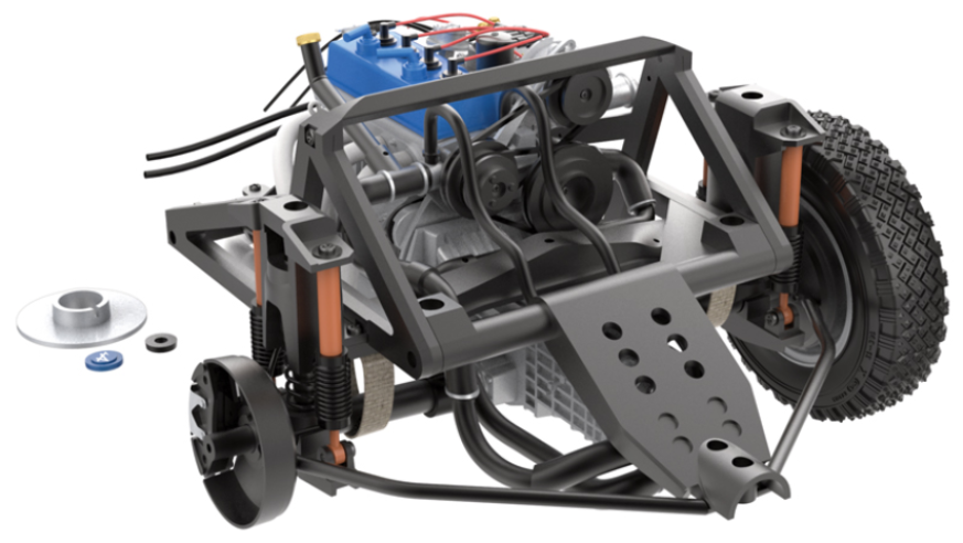
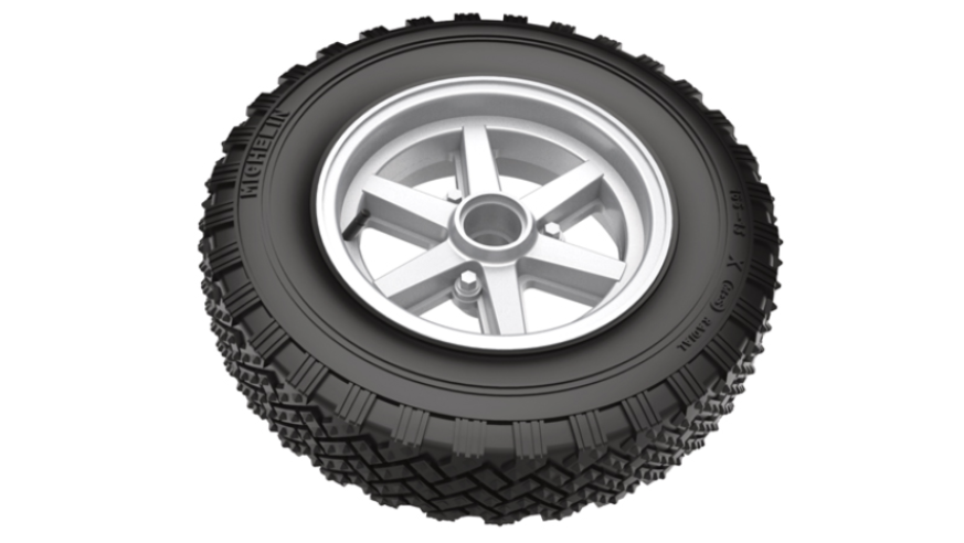
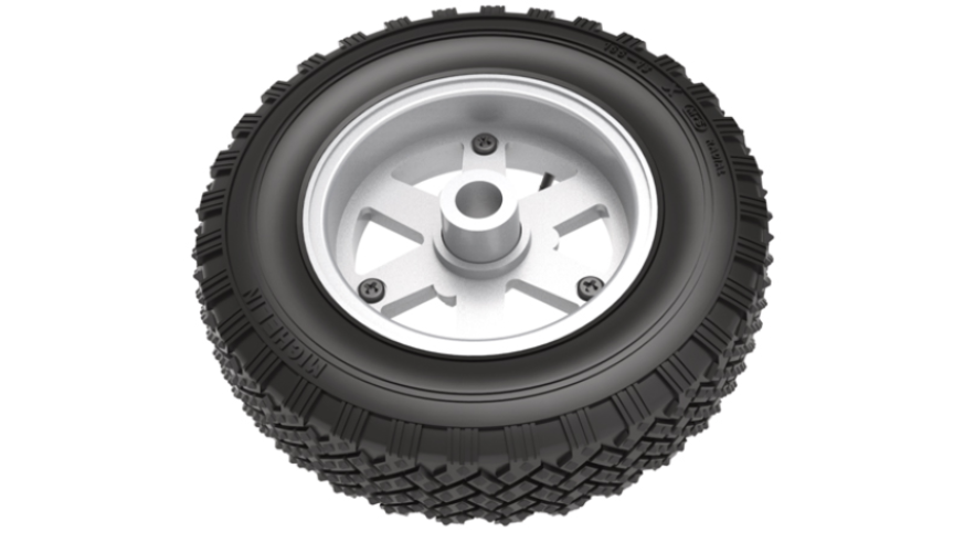
ASSEMBLY DIAGRAM
GENERAL VIEW
Kit 27 - Assembly of the right rear brake disc and the right rear wheel
Parts of kit
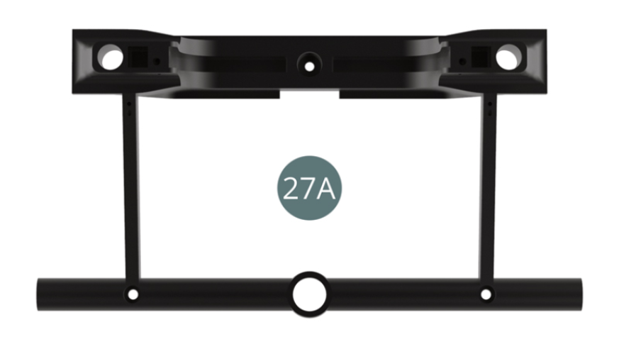
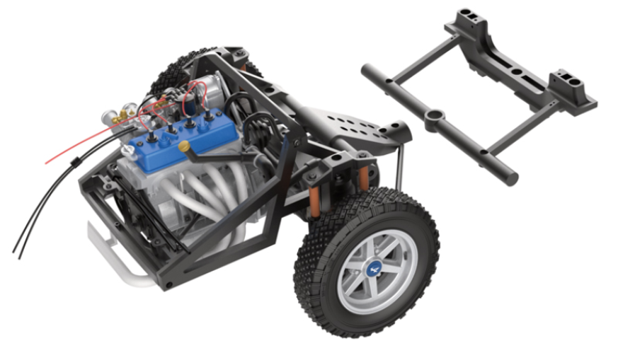
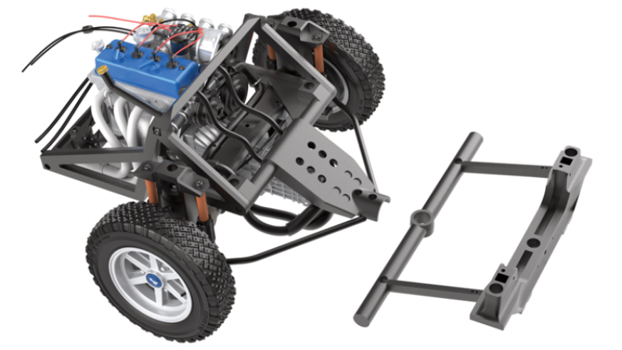
- 27A Cross bar front frame
- ABM Vis M 1,7 x 6 mm (x 3)
- VM Vis M 2,3 x 4 x 6 mm (x 3)
- BM Vis M 1,7 x 5 mm (x 2)
STEP 1
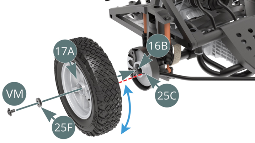
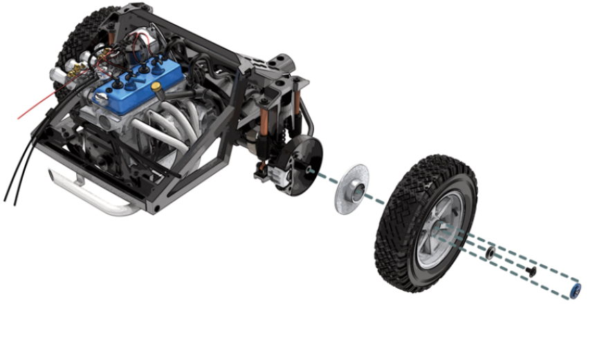
Position the brake disc (25C) on the right-hand drive shaft (16B) while engaging the brake caliper (25B) and dust cover (25A).
Position the pre-assembled wheel on the right-hand transmission shaft (16B) via the outer wheel rim (17A). Rotate it back and forth so that it fits into the notch on the brake disc (25C) - red dotted line - and secure it with a VM screw that has been passed through the washer (25F).
STEP 2
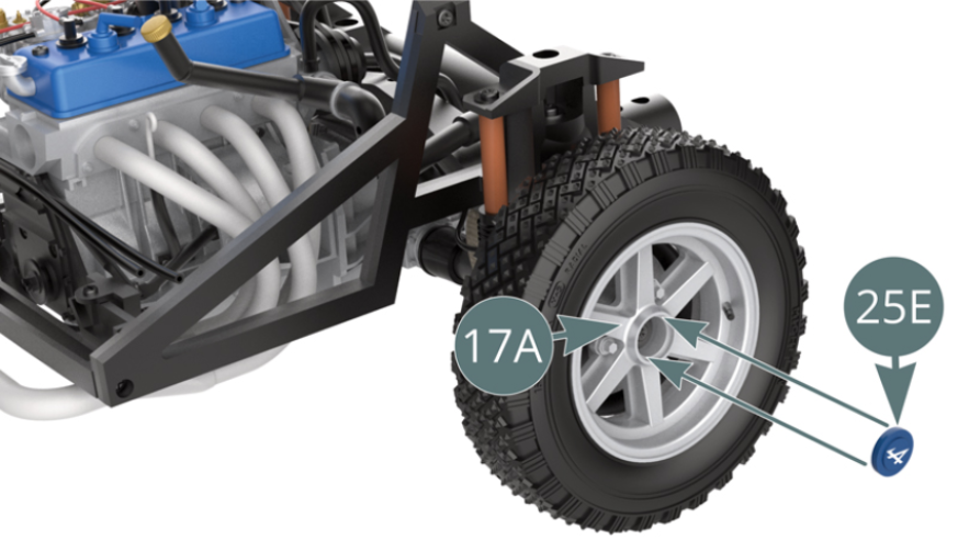
Position the hub cover (25E) on the outer wheel rim (17A).
ASSEMBLY DIAGRAM
GENERAL VIEW
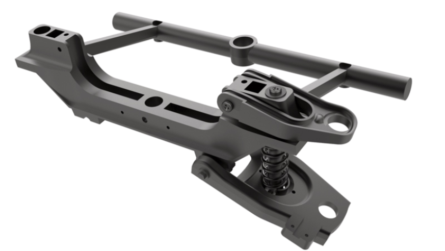
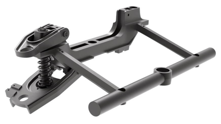
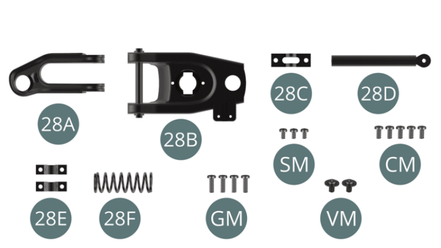
Kit 28 - Assembly of the left front suspension
Parts of kit
- 28A Upper left suspension arm
- 28B Lower left suspension arm
- 28C Support bracket
- 28D Strut
- 28E Clamp (x 2)
- 28F Suspension spring
- Screw GM M 2.0 x 6 mm (x 4)
- Screw SM M 1.7 x 3 mm (x 3)
- Screw CM M 2.0 x 4 mm (x 5)
- Screw VM M 2.3 x 4 x 6 mm (x 2)
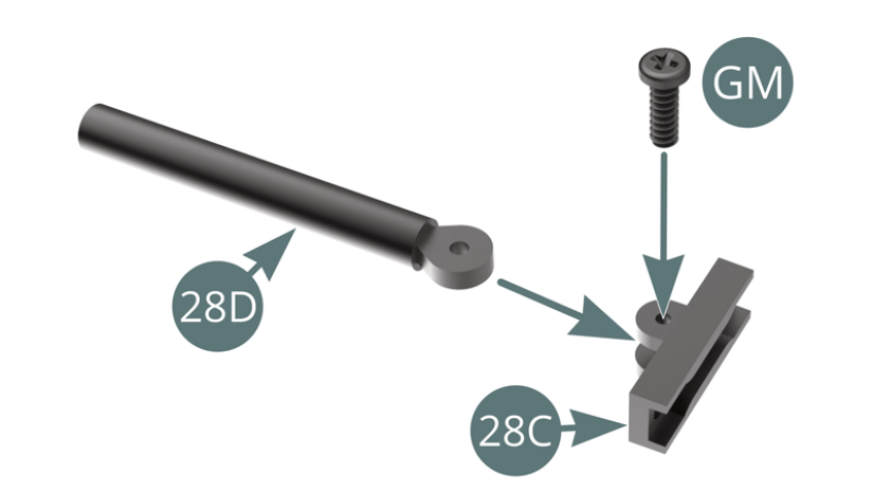
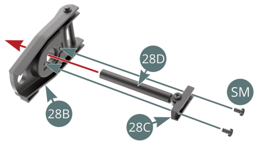
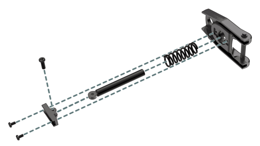
STEP 1
Position the strut (28D) to the support bracket (28C) and secure it with a GM screw. Position the support bracket (28C) to the left lower suspension arm (28B) and secure with two SM screws.
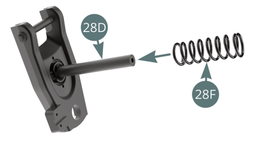
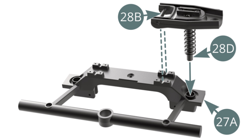
STEP 2
Position the spring (28F) on the strut (28D). Position the strut (28D) and left lower suspension arm (28B) onto the front cross bar (27A).
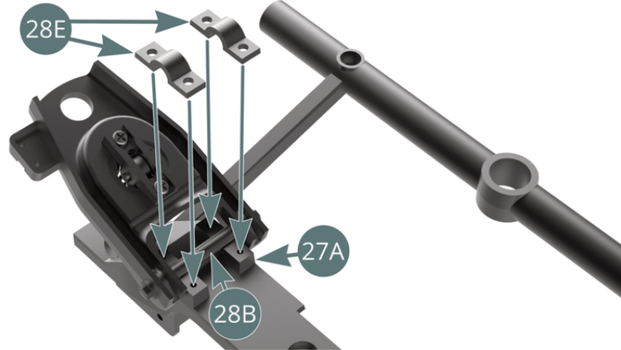
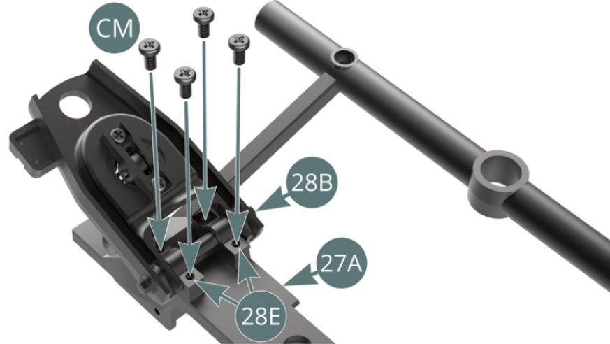
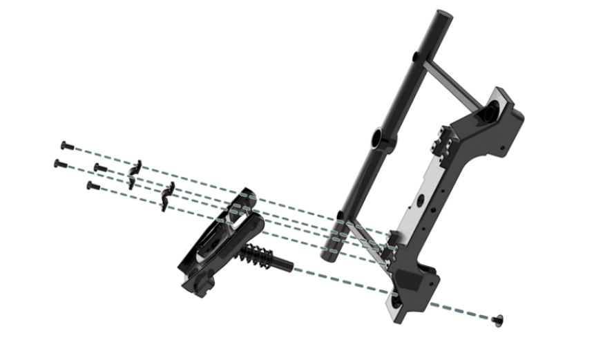
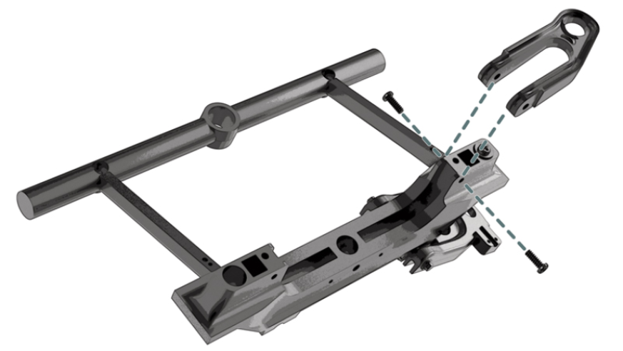
STEP 3
Secure the lower left suspension arm axle (28B) to the front frame cross bar (27A) using two clamps (28E) and four CM screws (shown opposite).
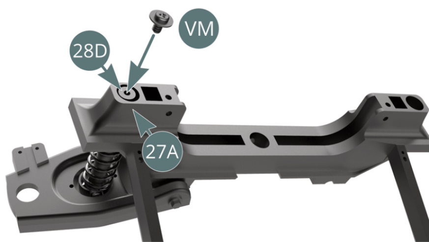
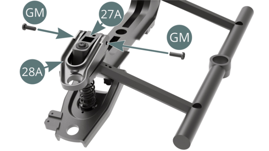
STEP 4
Attach the end of the strut (28D) to the front frame cross bar (27A) with a VM screw. Attach the left lower suspension arm (28B) to the front frame cross bar (27A) with two GM screws.
ASSEMBLY DIAGRAM
GENERAL VIEW