English
 français
 Deutsch
 español
 italiano
 português


Box 8
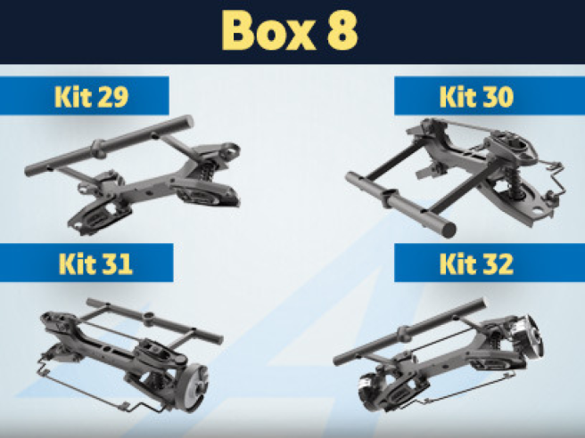
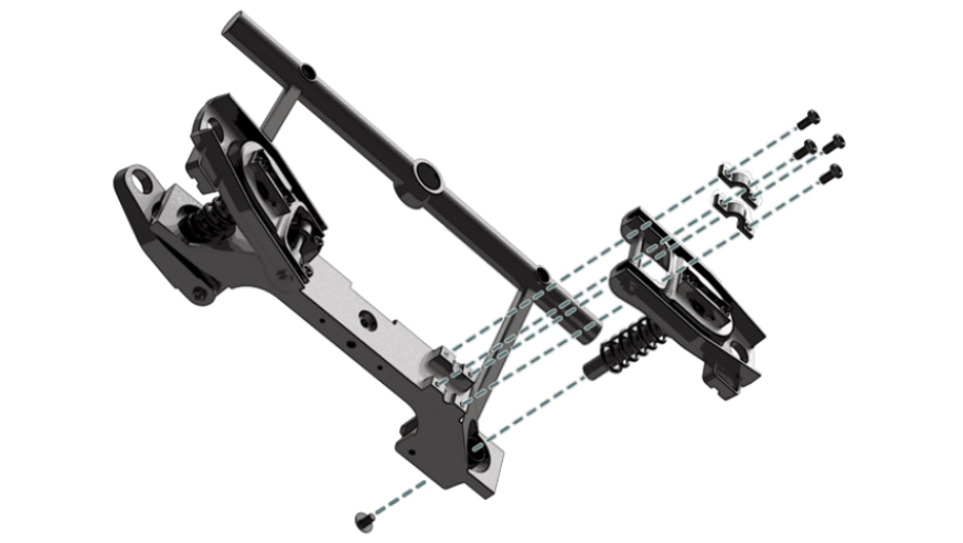
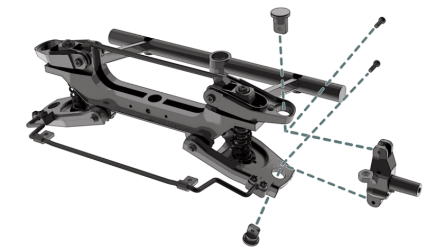
Kit 29 - Right front suspension assembly
Parts of kit
- 29A Upper right suspension arm
- 29B Lower right suspension arm
- 29C Mounting bracket
- 29D Strut
- 29E Fixing bracket (x 2)
- 29F Suspension spring
- Screw GM M 2.0 x 6 mm (x 4)
- Screw SM M 1.7 x 3 mm (x 3)
- Screw CM M 2.0 x 4 mm (x 5)
- Screw VM M 2.3 x 4 x 6 mm (x 2)

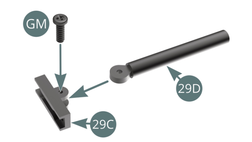
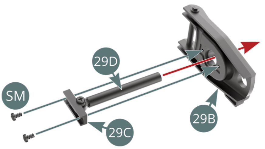
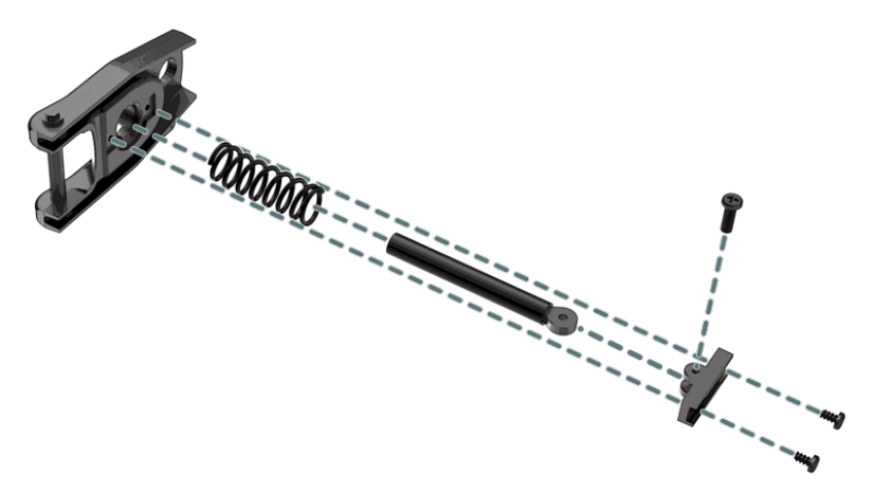
Step 1
Position the strut (29D) on the mounting bracket (29C) and secure it with a GM screw. Position the bracket (29C) on the lower right suspension arm (29B) and secure with two SM screws.
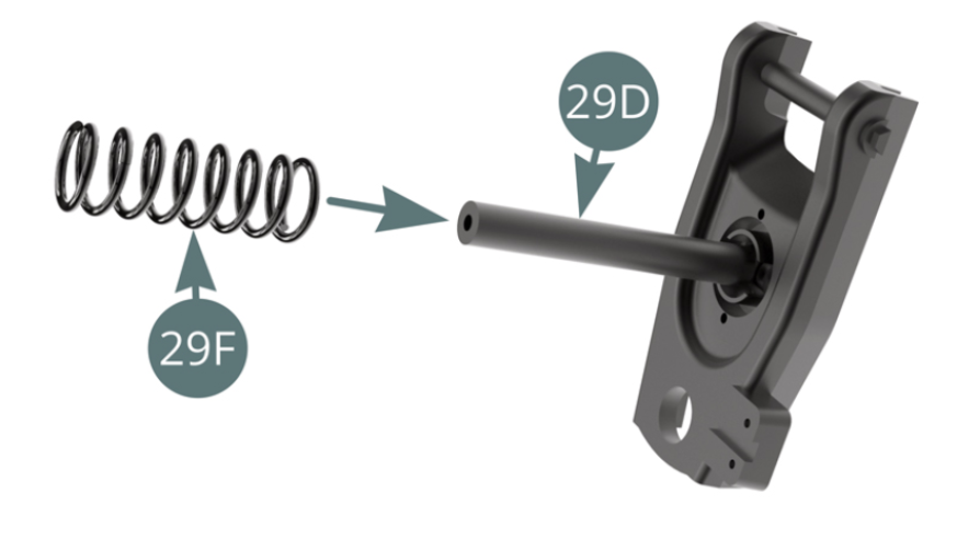
Step 2
Place the spring (29F) on the strut (29D). Position the strut (29D) and the lower right suspension arm (29B) onto the front frame cross bar (27A).
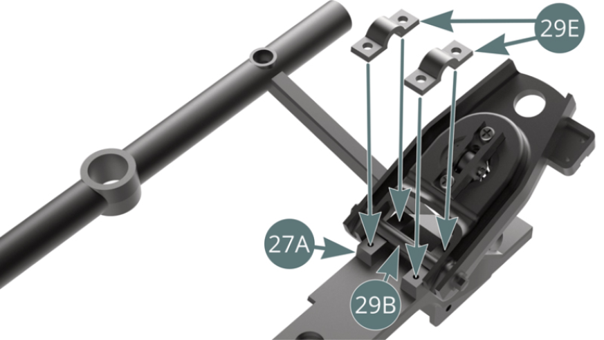
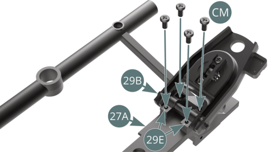
Step 3
Secure the lower right suspension arm axis (29B) to the front frame cross bar (27A) using two brackets (29E) and four CM screws (shown opposite and below).
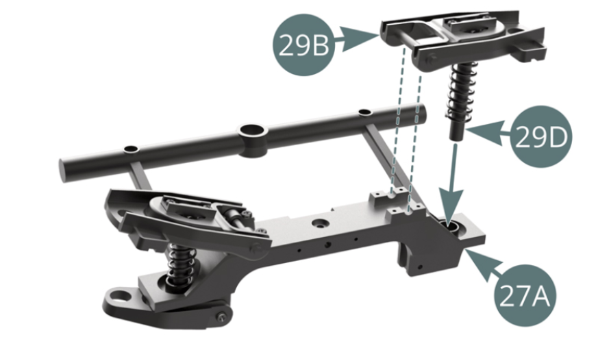
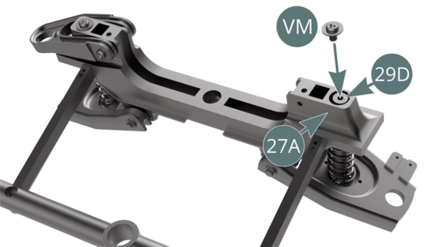
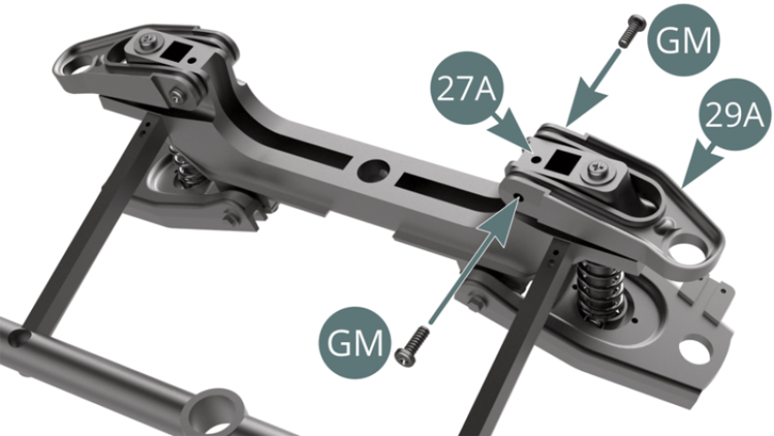
Step 4
Attach the end of the strut (29D) to the front frame cross bar (27A) with a VM screw. Attach the lower right suspension arm (29B) to the front frame cross bar (27A) with two GM screws.
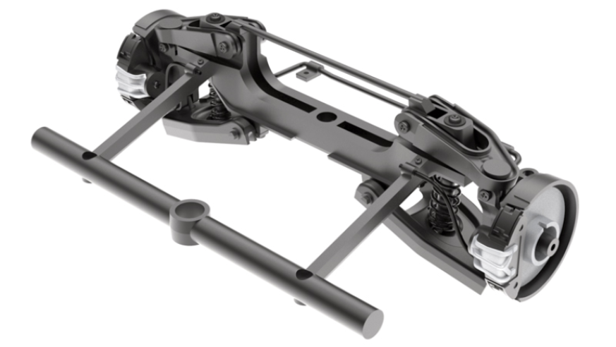
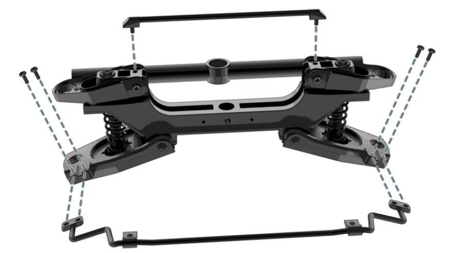
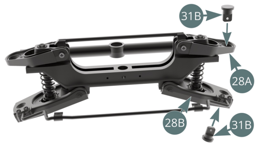
ASSEMBLY DIAGRAM
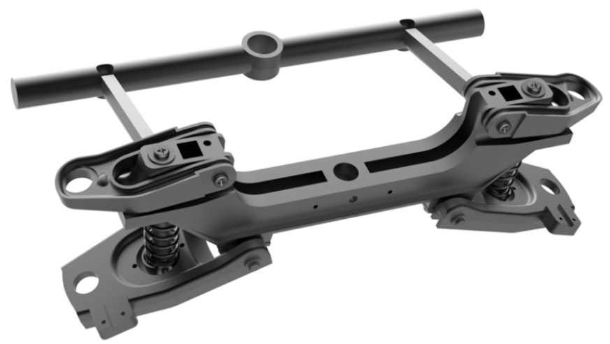
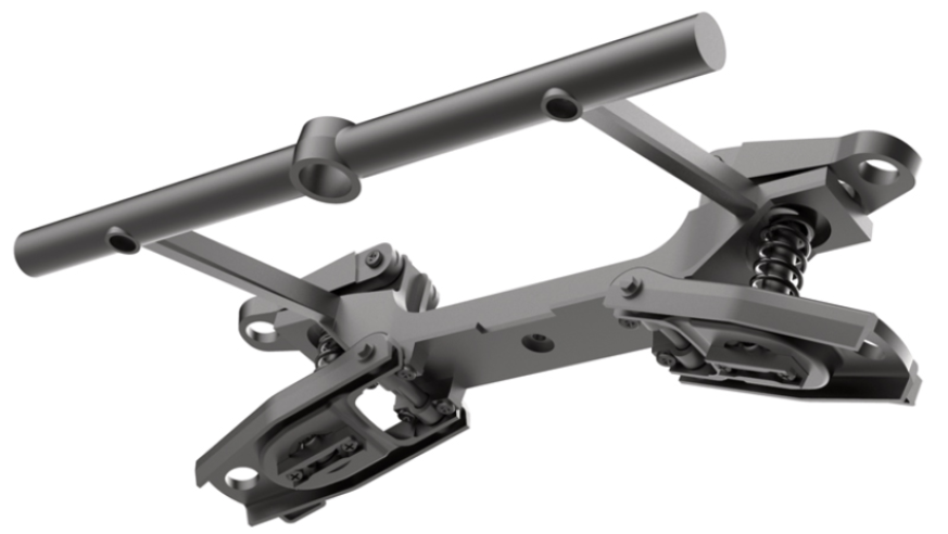
GENERAL VIEW
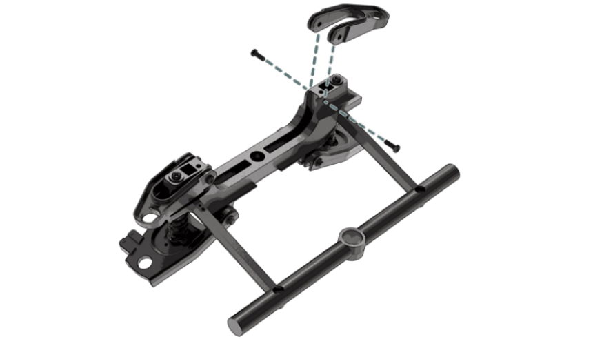
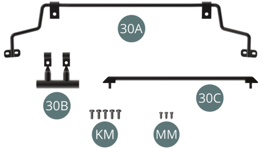
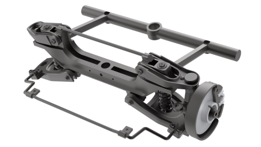
Kit 30 - Assembly of the front suspension
Parts of kit
- 30A Roll bar
- 30B Mounting bracket (x 2)
- 30C Upper bar
- Screw KM M 1.4 x 4 mm (x 5)
- Screw MM M 1.2 x 3 mm (x 3)
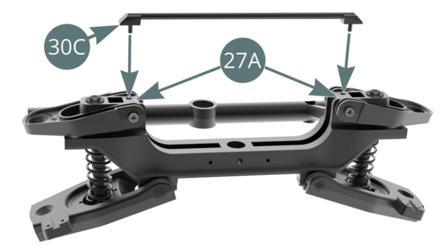
Step 1
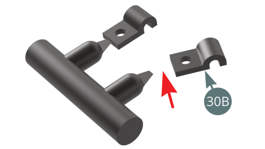
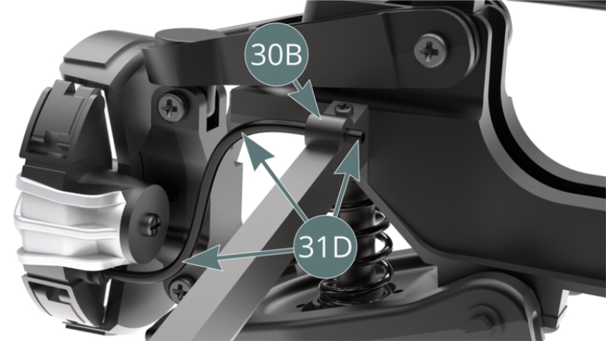
Detach the two mounting brackets 30B from the molding cluster.
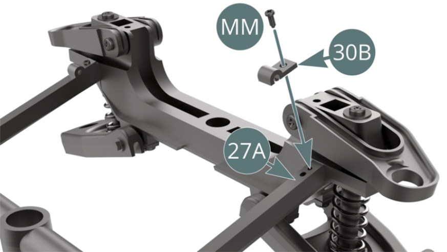
Place a support bracket (30B) on the left side of the front frame cross bar (27A) and secure with an MM screw.
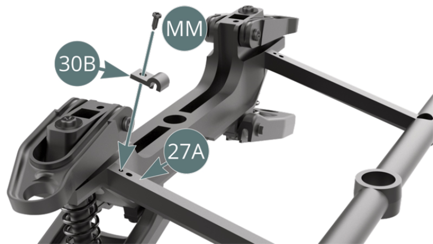
Etape 2
Place the other mounting bracket (30B) on the right side of the front frame cross bar (27A) and secure it with an MM screw. Place the upper bar (30C) on the front frame cross bar (27A).
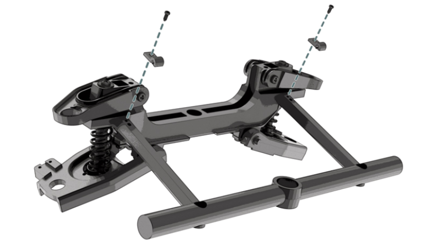
Etape 3
Place the brackets at the tips of the roll bar (30A) on the right (29B) and left (28B) lower suspension arms, and secure each bracket with two KM screws.

Schéma d’assemblage
Vue générale
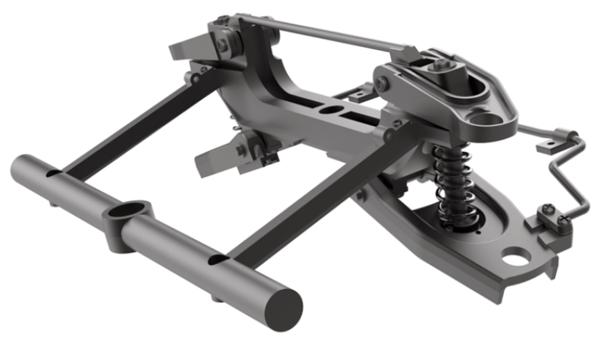
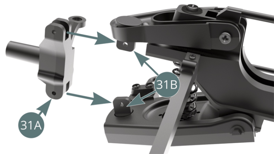
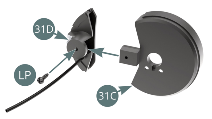
Kit 31 - Left front brake assembly and installation on the suspension
Parts of kit
- 31A Hub carrier left
- 31B Stud (x 2)
- 31C Dust cover
- 31D Brake caliper and hose
- 31E Brake disc
- Screw LP M 1.4 x 5 mm (x 2)
- Screw MM M 1.2 x 3 mm (x 3)
- Screw WM M 2.0 x 7 mm (x 2)
- Screw AEM M 2.0 x 8 mm (x 2)

Step 1
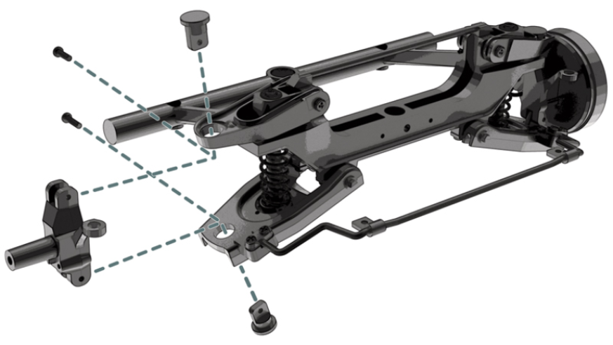
Place the studs (31B) into the upper left suspension arm (28A) and the lower left suspension arm (28B).
Step 2
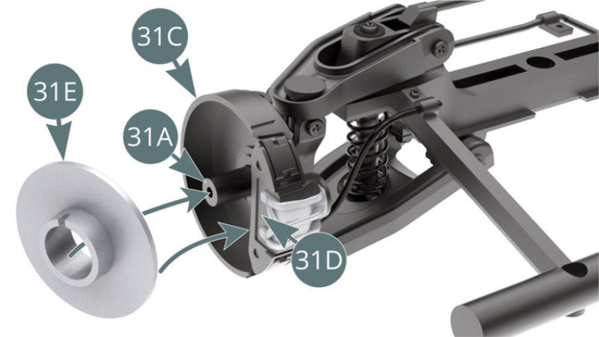
Position the left hub carrier (31A) between the two studs (31B) and secure with a WM screw at the top and an AEM screw at the bottom (shown opposite and below).

Step 3
Position the dust cover (31C) on the brake caliper (31D) and secure with an LP screw. Place the dust cover (31C) on the left hub carrier (31A) and secure with two MM screws.
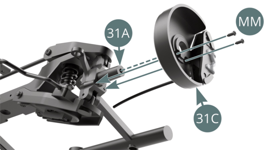
Step 4
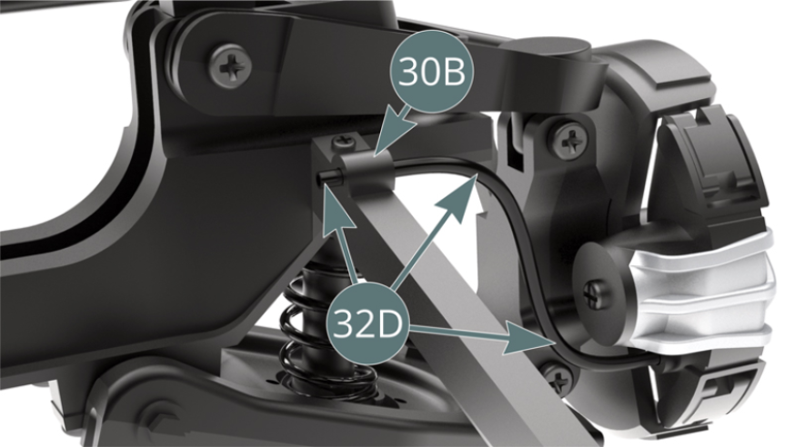
Pass the end of the brake hose (31D) through the stud (30B). Place the brake disc (31E) on the left hub carrier (31A) while engaging the dust cover (31C) and brake caliper (31D).
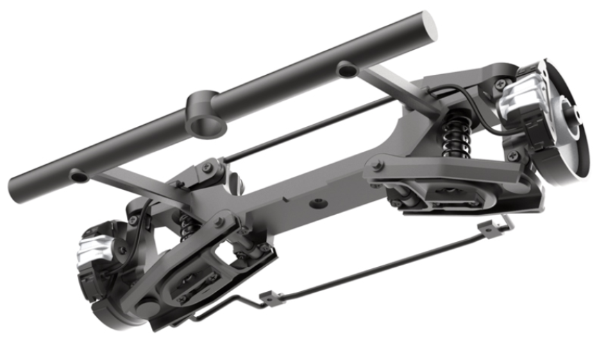
ASSEMBLY DIAGRAM
GENERAL VIEW
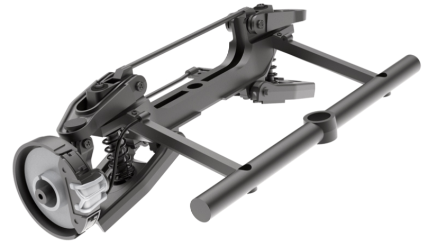
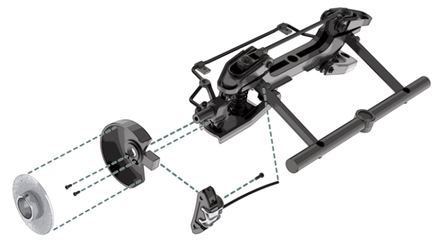
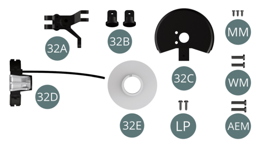
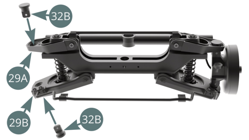
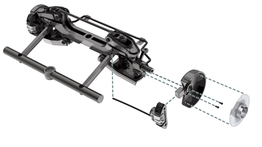
Kit 32 - Right front brake assembly and installation on the suspension
Parts of kit
- 32A Hub carrier, right
- 32B Stud (x 2)
- 32C Dust cover
- 32D Brake caliper and hose
- 32E Brake disc
- Screw LP M 1.4 x 5 mm (x 2)
- Screw MM M 1.2 x 3 mm (x 3)
- Screw WM M 2.0 x 7 mm (x 2)
- Screw AEM M 2.0 x 8 mm (x 2)
Step 1
Place the studs (32B) into the upper right suspension arm (29A) and the lower right suspension arm (29B).
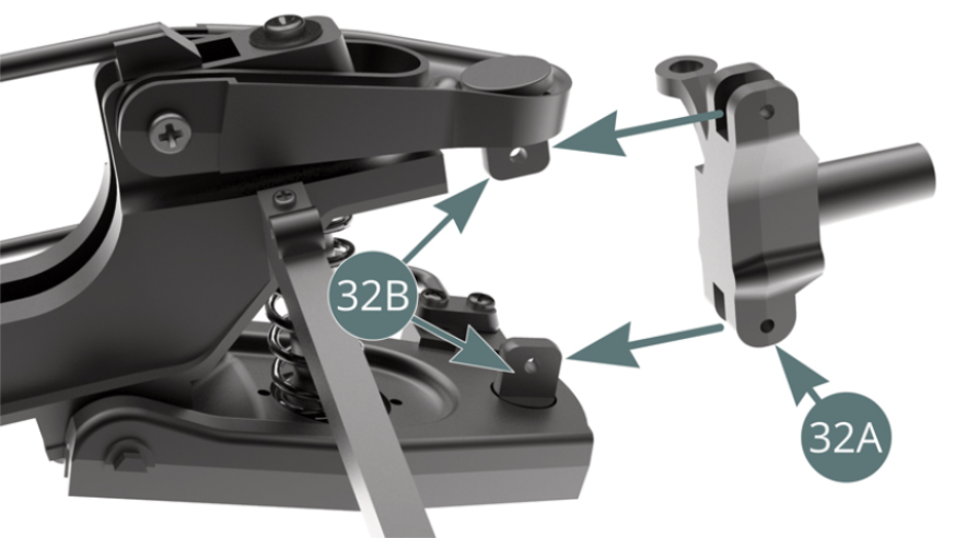
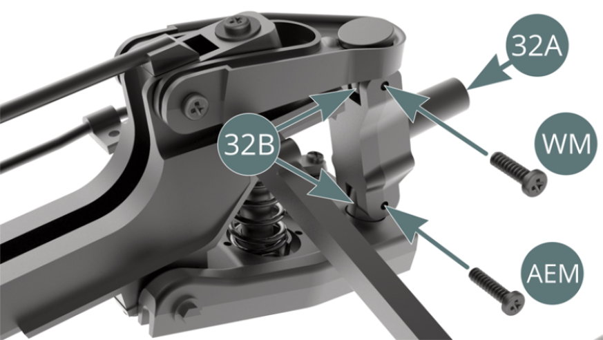
Step 2
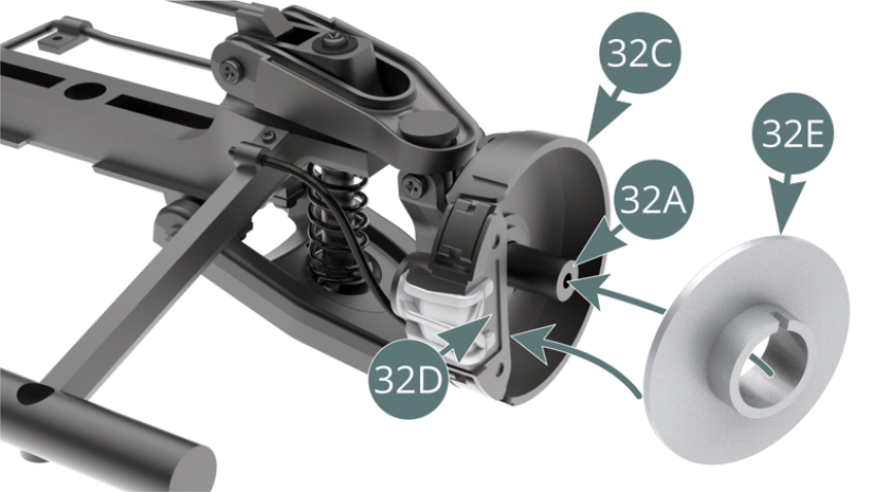
Position the left hub carrier (32A) between the two studs (32B) and secure with a WM screw at the top and an AEM screw at the bottom (shown opposite and below).
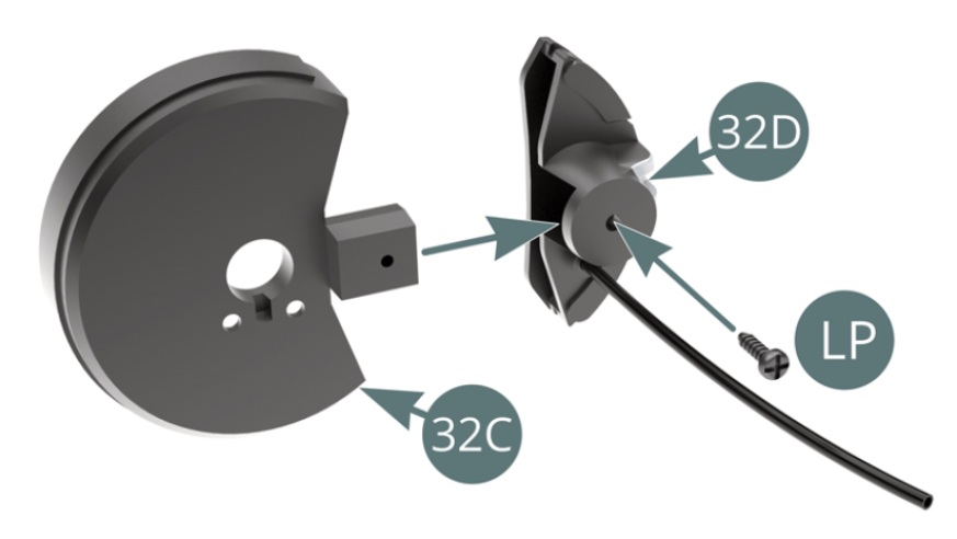
Step 3
Place the dust cover (32C) on the brake caliper (32D) and secure with an LP screw. Position the dust cover (32C) on the left hub carrier (32A) and secure with two MM screws.
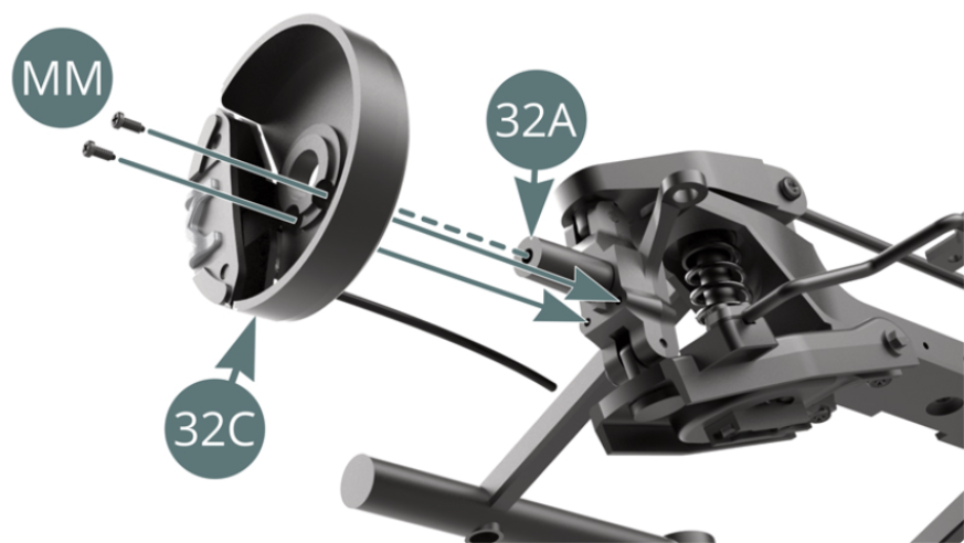
Step 4
Pass the end of the brake hose (32D) through the stud (30B). Place the brake disc (32E) on the left hub carrier (32A) while engaging the dust cover (32C) and brake caliper (32D).
ASSEMBLY DIAGRAM
GENERAL VIEW