English
 français
 Deutsch
 español
 italiano
 português


Box 9
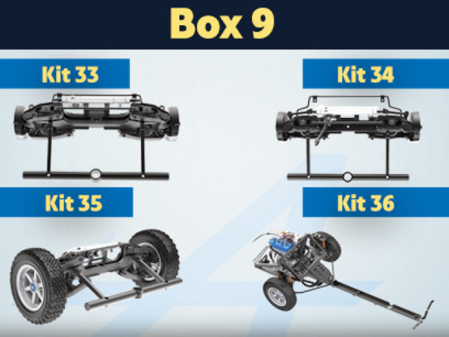
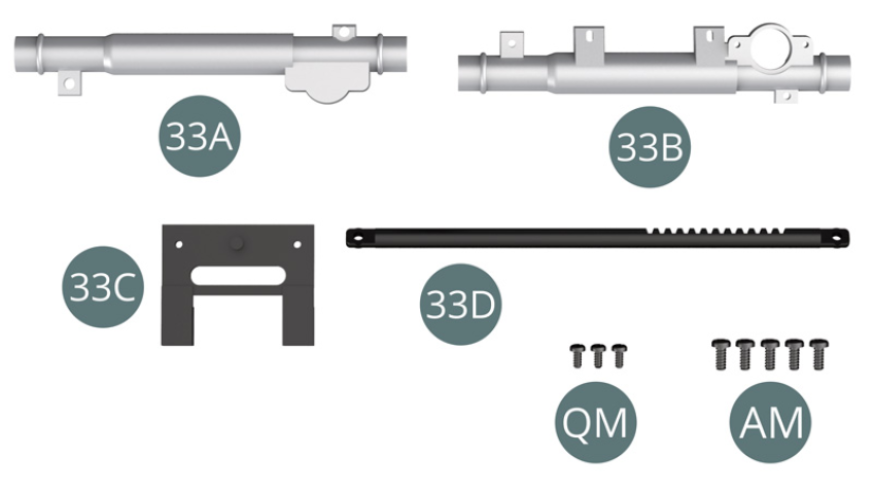
Kit 33 - Steering rack assembly and mounting
Parts of kit
- 33A Rack half-column
- 33B Rack half-column
- 33C Support
- 33D Steering rack
- Screw QM M 1.4 x 3 mm (x 3)
- Screw AM M 1.7 x 4 mm (x 5)
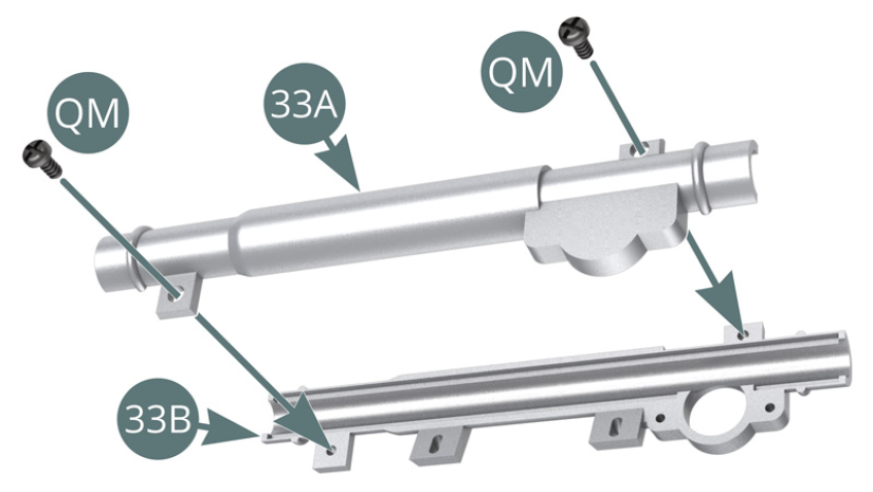
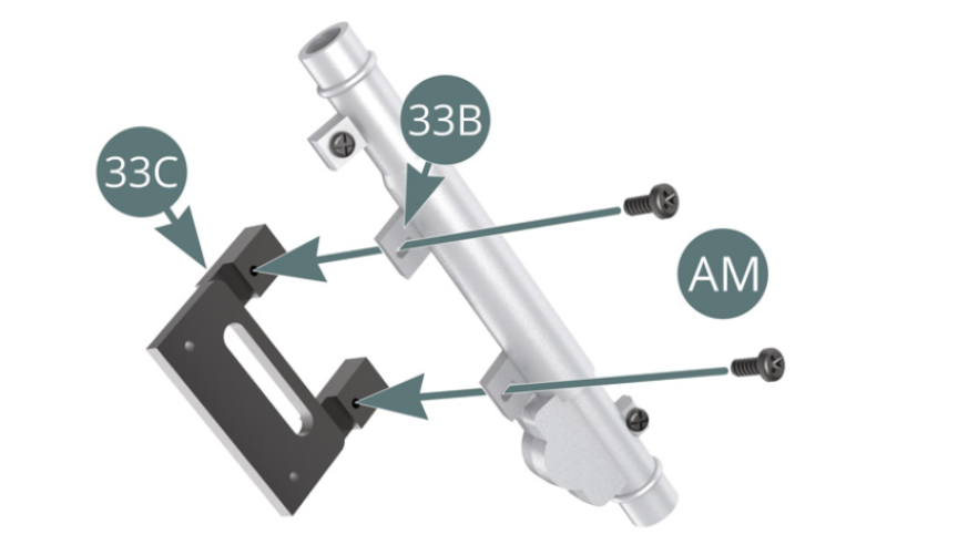
Step 1
Position the rack half-columns (33A and 33B) on top of each other and attach them together with two QM screws. Place the rack column (33B) on the support (33C) and secure with two AM screws.
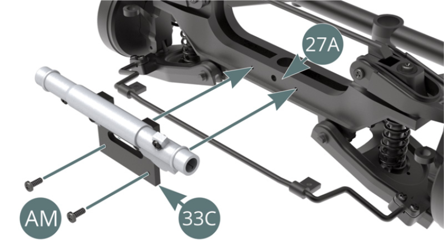
Step 2
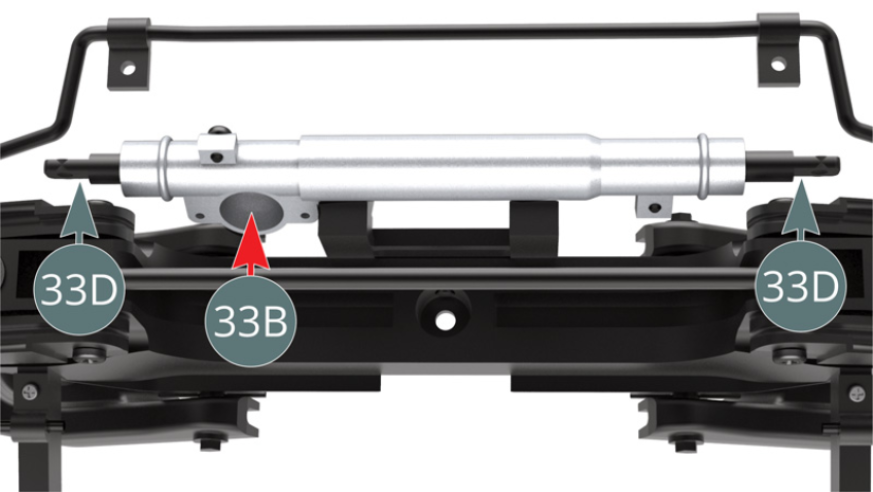
Position the support (33C) on the cross bar front frame (27A) and secure with two AM screws. Slide the steering rack (33D) into the rack column (33B), please take note of the direction of the rack teeth - red arrow.
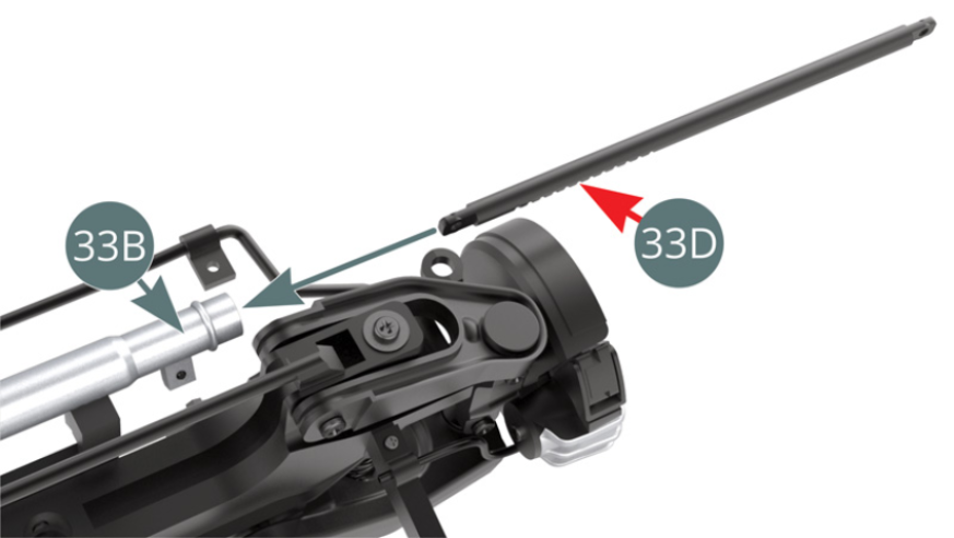
Step 3
Centre the steering rack (33D) in the rack column (33B) and ensure that the teeth of the rack are visible through the opening in the column - red arrow.

ASSEMBLY DIAGRAM
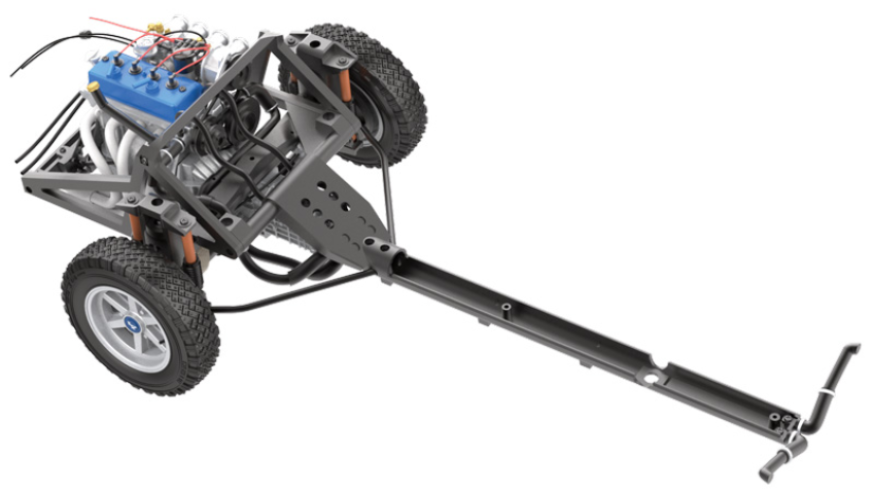
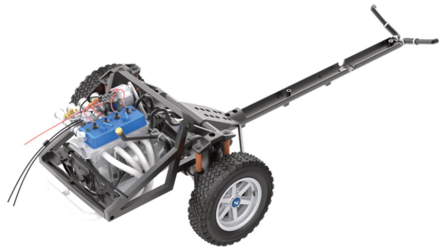
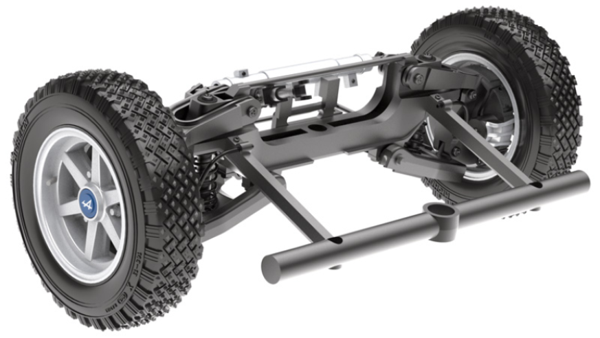
GENERAL VIEW
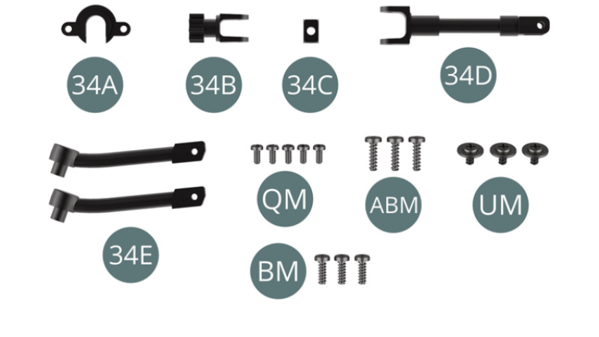
Kit 34 - Assembly of the steering box
Parts of kit
- 34A Flange
- 34B Steering pinion
- 34C Universal joint
- 34D Intermediate shaft
- 34E Steering tie rod (x 2)
- Screw QM M 1.4 x 3 mm (x 5)
- Screw ABM M 1.7 x 6 mm (x 3)
- Screw UM M 1.7 x 3 x 5.5 mm (x 3)
- Screw BM M 1.7 x 5 mm (x 3)
Step 1
Centre the steering rack (33D) in the rack column (33B) and ensure that the teeth of the rack are visible through the opening in the column - red arrow.
Step 2
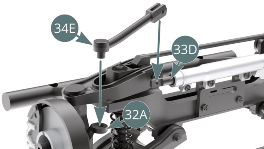
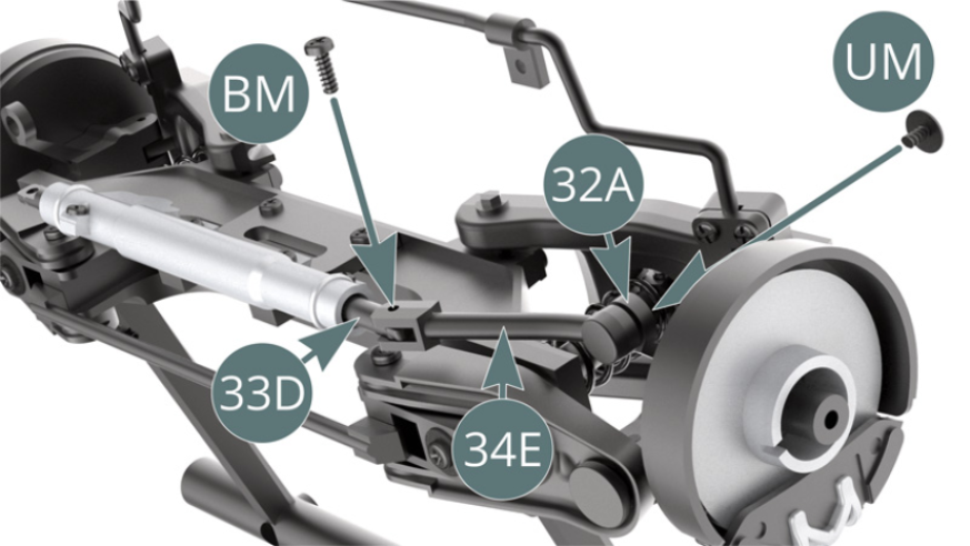
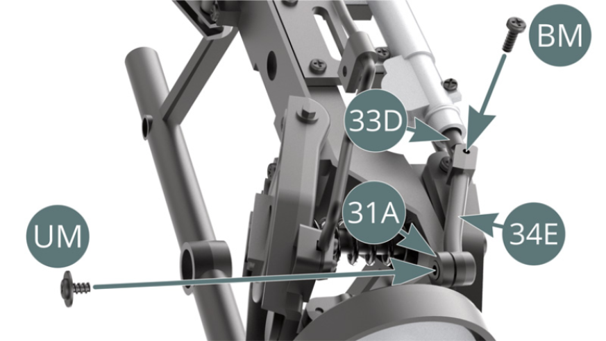
Place the steering tie rod (34E) on the steering rack (33D) and onto the right hub carrier (32A). Attach the steering tie rod (34E) to the steering rack (33D) with a BM screw and to the right hub carrier (32A) with a UM screw.
Step 3
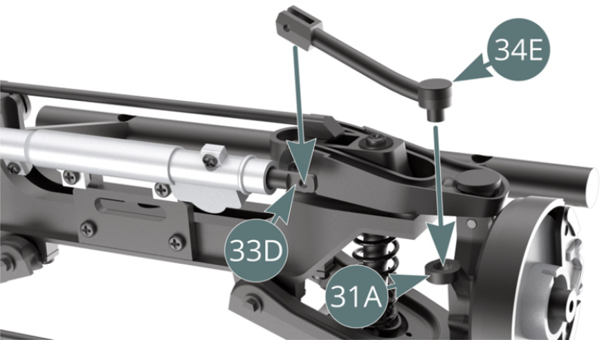
Place the steering tie rod (34E) on the steering rack (33D) and onto the left hub carrier (31A). Attach the steering tie rod (34E) to the steering rack (33D) with a BM screw and to the left hub carrier (31A) with a UM screw.
Step 4
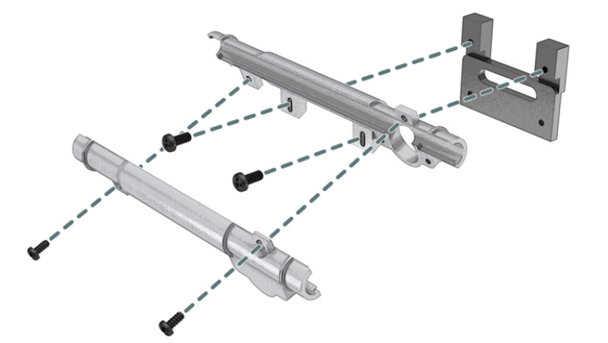
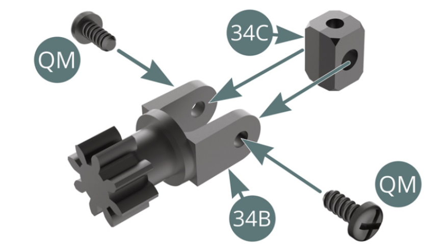
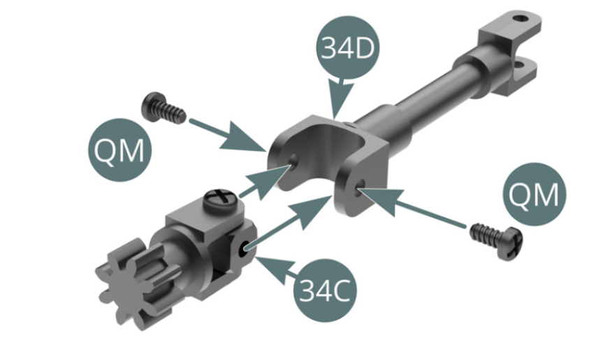
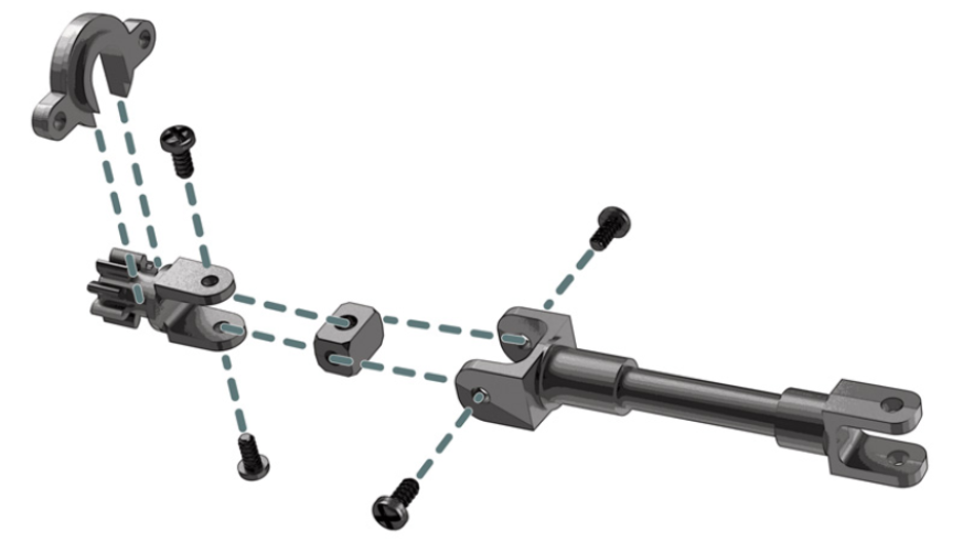
Position the universal joint (34C) on the steering pinion (34B) and secure with two QM screws. Position the universal joint (34C) on the fork of the intermediate shaft (34D) and secure it with two QM screws.
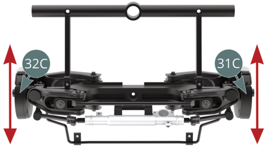
Step 5
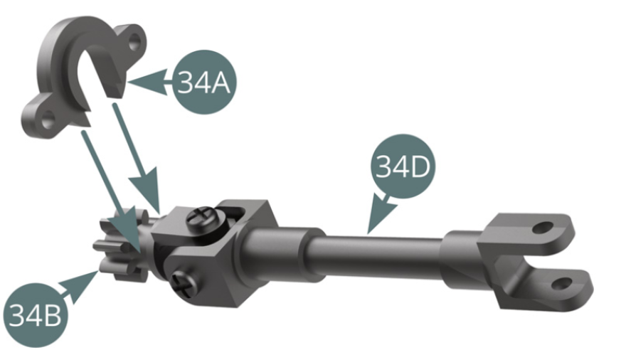
Place the flange (34A) above the steering pinion neck (34B). Align the left (31C) and right (32C) dust covers parallel and lengthwise - red arrows.
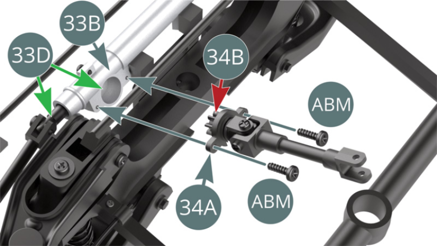
Step 6
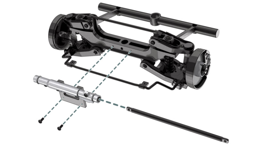
Position the steering pinion (34B) and flange (34A) onto the rack column (33B), insert the steering pinion (34B) onto the steering rack (33D) and secure with two ABM screws.
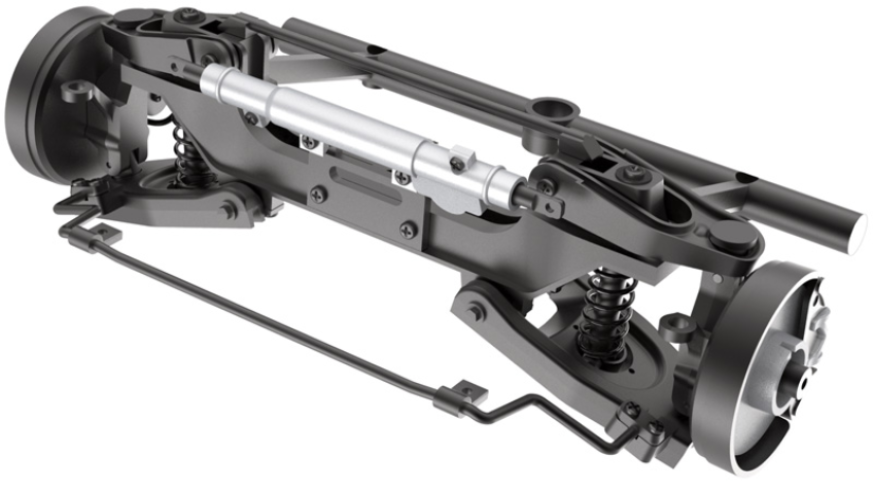
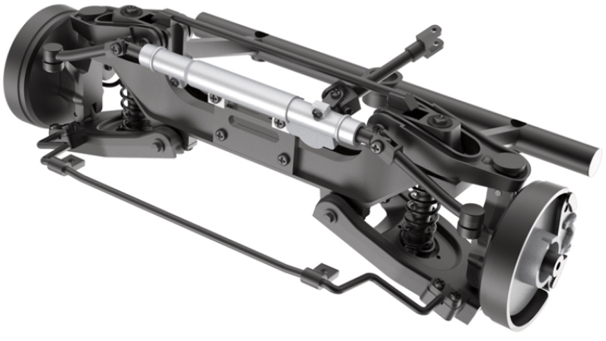
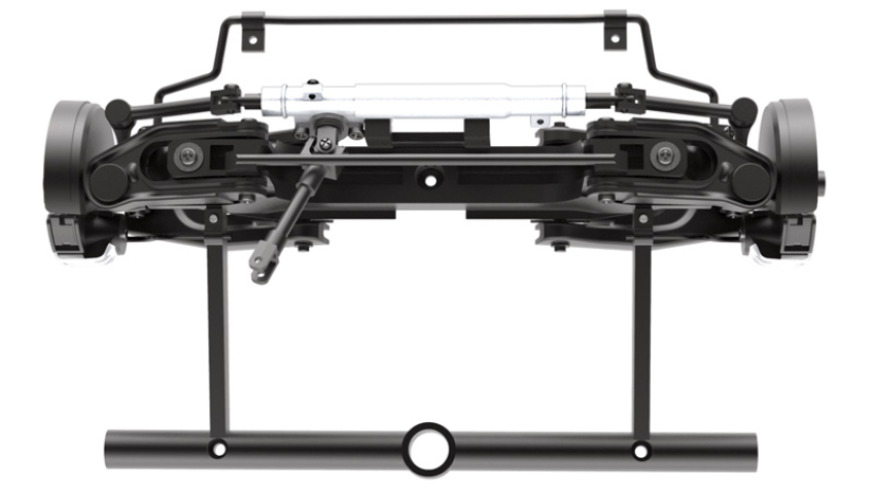
ASSEMBLY DIAGRAM
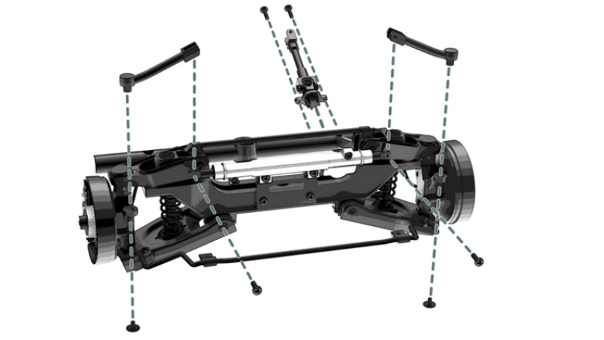
GENERAL VIEW
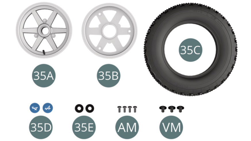
Assembly of the fourth and last wheel, mounting the wheels to the front suspension
- 35E Washer (x 2)
- Screw AM M 1.7 x 4 mm (x 4)
- Screw VM M 2.3 x 4 x 6 mm (x 3)
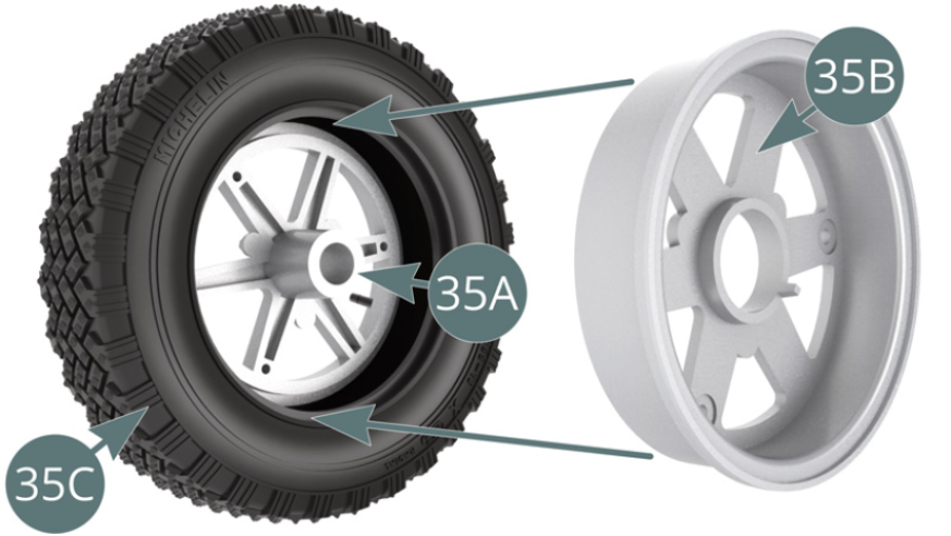
Step 1
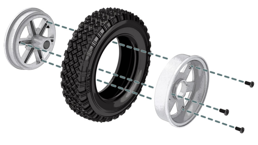
Place the outer wheel rim (35A) in the tyre (35C).
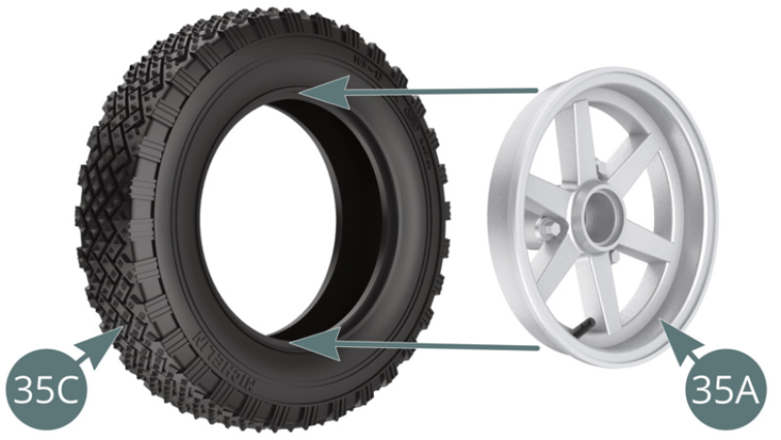
Step 2
Position the inner wheel rim (35B) in the tyre (35C), aligning it with the outer rim (35A) and fasten it with three AM screws - illustrations above.

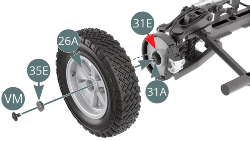
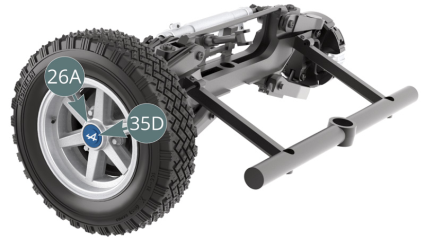
Step 3
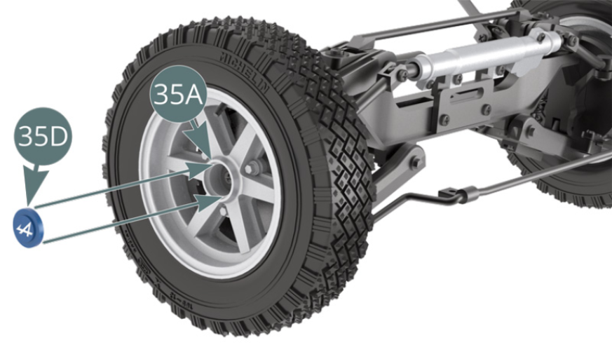
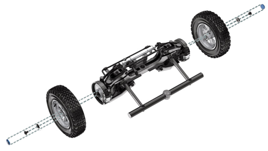
Position the previously assembled wheel onto the left hub carrier (31A) through the outer wheel rim (26A). Rotate it back and forth to engage the notch located on the brake disc (31E) - red arrow -, then secure it with a VM screw previously passed through the washer (35E). Position the hub cap (35D) on the outer wheel rim (26A).
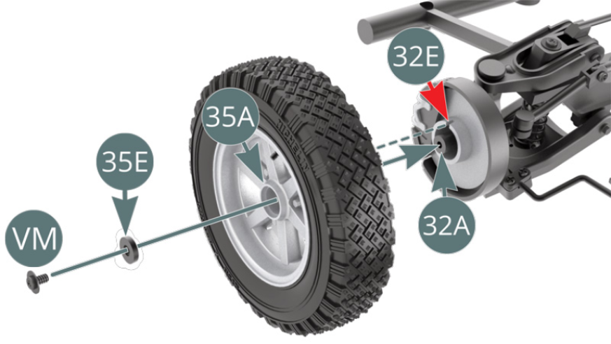
Step 4
Position the last assembled wheel onto the right hub carrier (32A) through the outer wheel rim (35A). Rotate it back and forth to engage the notch located on the brake disc (32E) - red arrow - and secure it with a VM screw previously passed through the washer (35E). Position the hub cap (35D) on the outer wheel rim (35A).
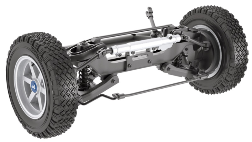
ASSEMBLY DIAGRAM
GENERAL VIEW
Kit 36 - Assembly of the chassis
Parts of kit
- 36A Central beam chassis
- 36B Water pipe left
- 36C Water pipe right
- Screw SM M 1.7 x 3 mm (x 3)
- Screw AAM M 2.3 x 5 mm (x 3)

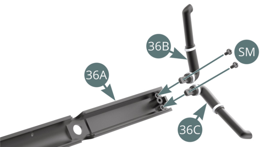
Step 1
Position the left (36B) and right (36C) water pipes on the central chassis beam (36A) and fix them with two SM screws.
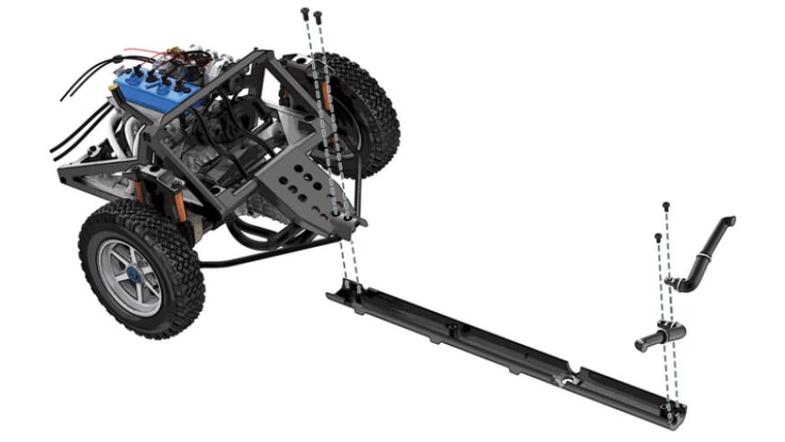
Now connect the chassis beam (36A) to the main frame (20A). In order to carry out this assembly step, carefully follow the three following illustrations (step 2 and step 3)
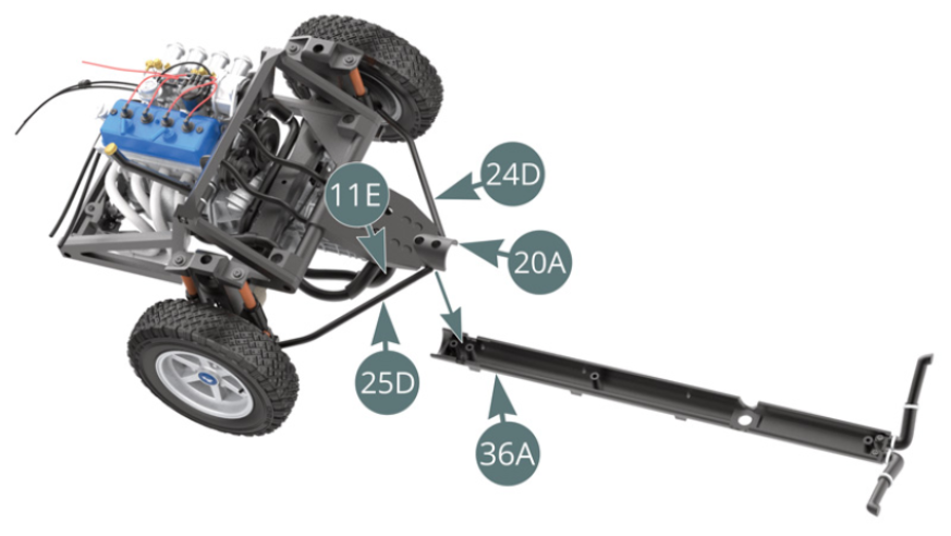
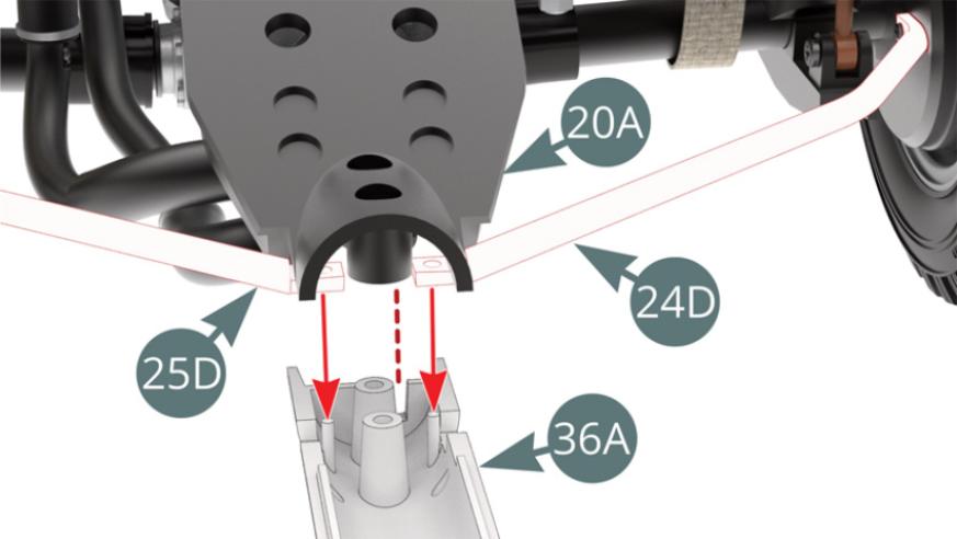
Step 2
When attaching the central chassis beam (36A) to the main frame (20A), ensure that the tab at the end of the hose (11E) fits into the slot indicated by the red arrow - shown above. At the same time, the holes at the end of the support arms (24D & 25D) must fit in position over the nipples provided on the central chassis beam (36A) - red arrows in the illustration above right.
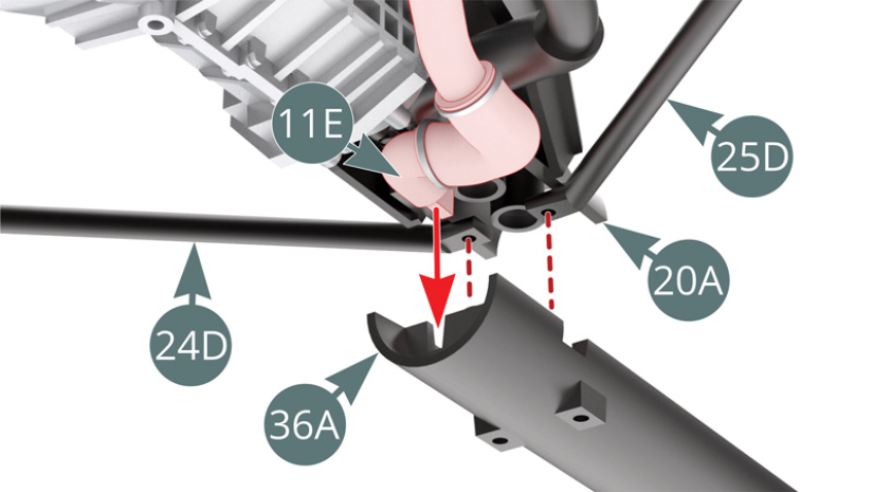
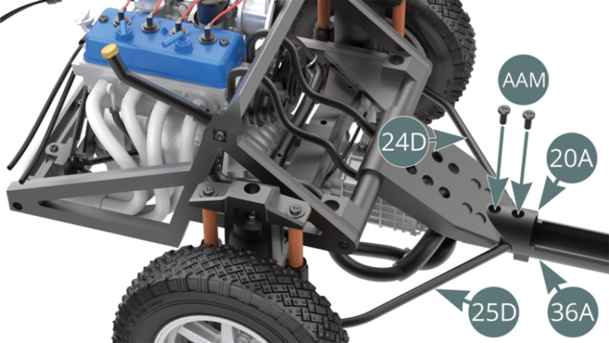
Step 3
When the central chassis beam (36A) is correctly positioned to the main frame (20A), fix it with two AAM screws.
ASSEMBLY DIAGRAM
GENERAL VIEW