English
 français
 Deutsch
 español
 italiano
 português


Box 10
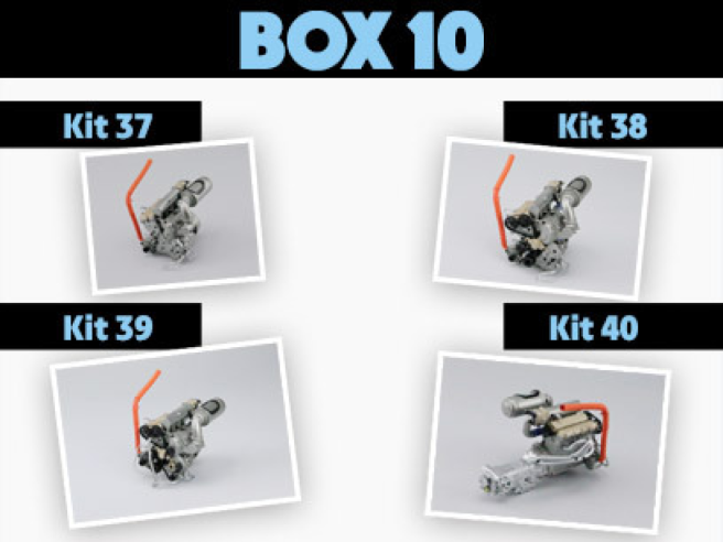
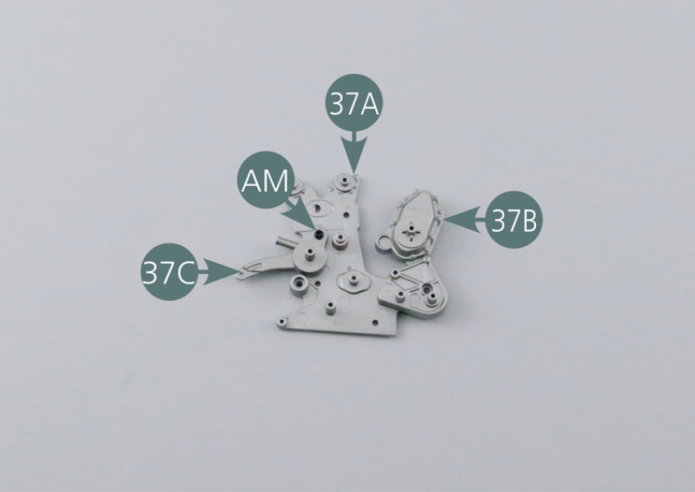
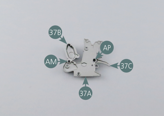
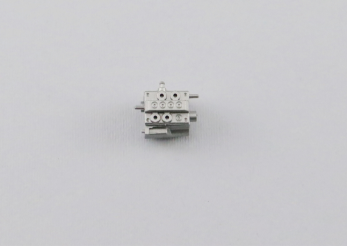
Kit 37 - ALTERNATOR AND INJECTION PUMP
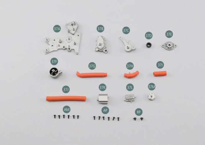
Parts of kit
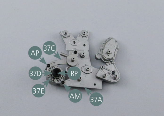
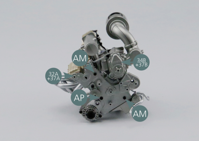
- 37A Front of engine
- 37B Turbocharger pulley bracket
- 37C Water pump
- 37D Pulley #7
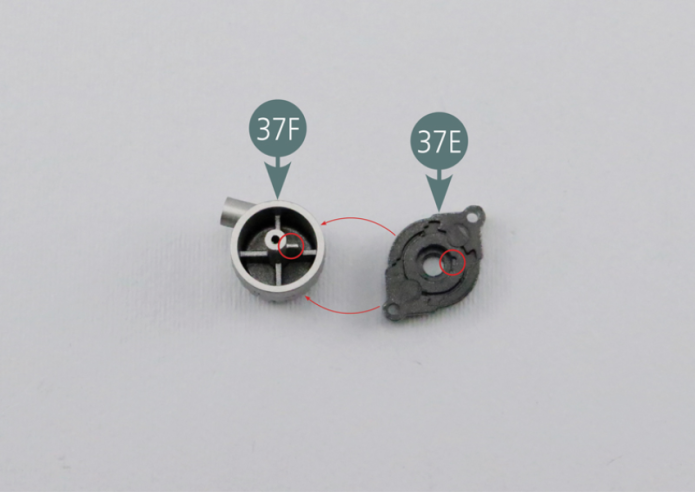
- 37E Housing alternator
- 37F Alternator
- 37G Air duct #1
- 37H Air duct #2
- 37I Air duct #3
- 37J Air duct #4
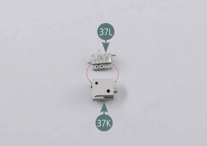
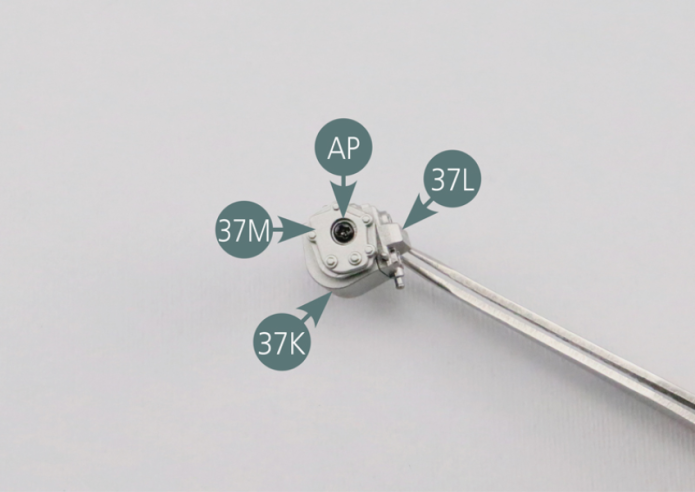
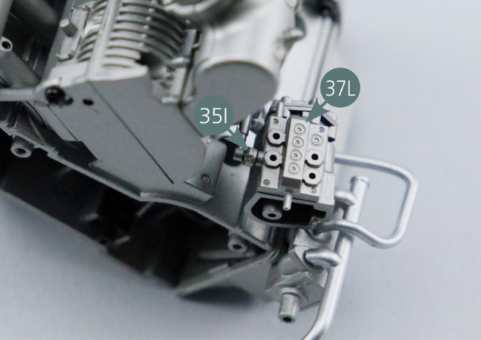
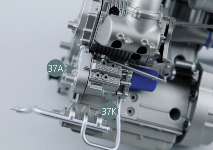
- 37K Injection pump
- 37L Injection Pump dispenser
- 37M Housing Injection pump
- Screw AM M 1.7 x 4 mm (x 6)
- Screw AP P 1.7 x 4 mm (x 6)
- Screw RP P 1.7 x 3 mm (x 2)
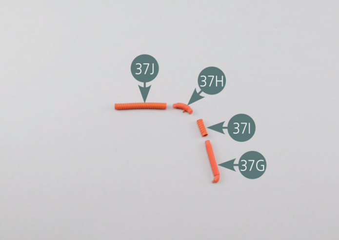
Step 1
Connect the four air ducts (37G, 37H, 37I & 37J) as shown in the photo.
Step 2
Place the water pump (37C) on the front of the engine (37A) and secure with an AM screw. Position the turbocharger pulley bracket (37B) on the front of the engine (37A) and secure with an AM screw. Secure the water pump (37C) with an AP screw.
Step 3
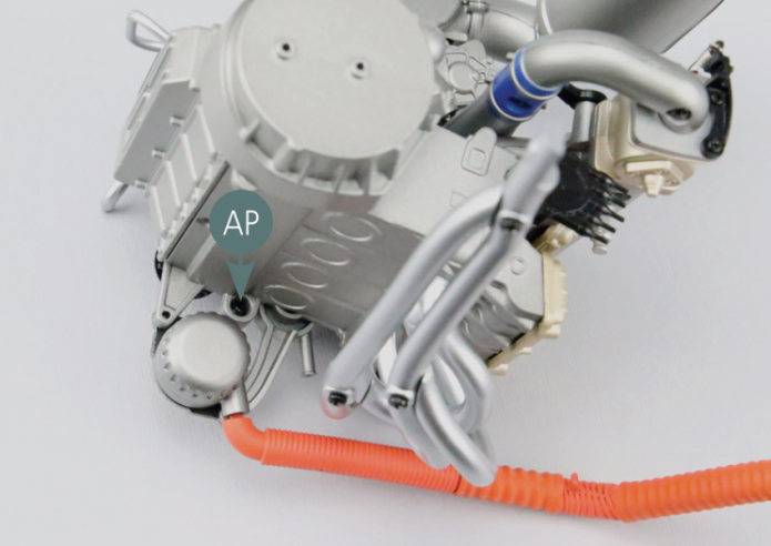
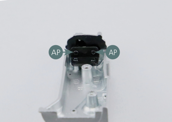
Place the injection pump dispenser (37L) on the injection pump (37K), then position the housing of the injection pump (37M) on this assembly and secure with an AP screw.
Step 4
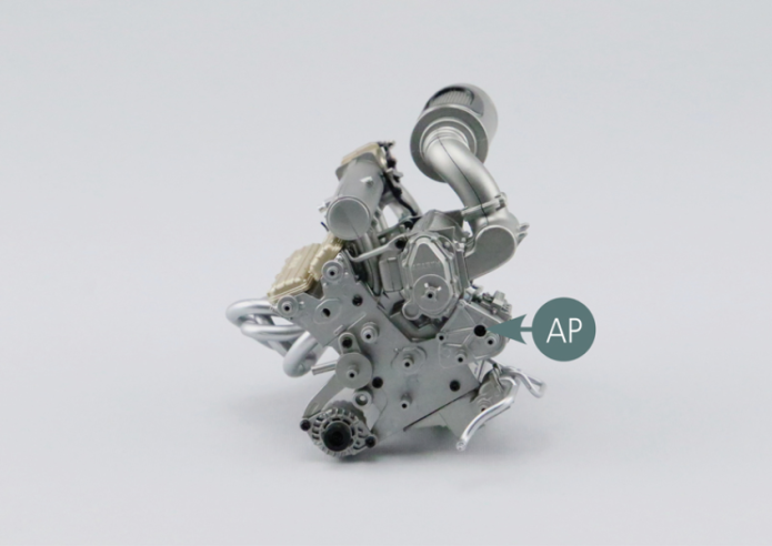
Place the housing of the alternator (37E) on the alternator (37F). Check the correct position of the mounting slot (red circle). Position the alternator on the water pump (37C) and the front of the engine (37A), then secure it an AP screw (top) and an AM screw (bottom). Place the pulley #7 (37D) on the alternator and secure with an RP screw.

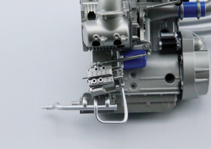
Step 5
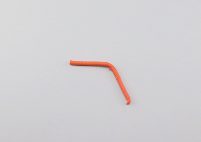
Position the injection pump near the oil filter, then connect the front accelerator lever (35I) to the widest shaft of the injection pump dispenser (37L).
Step 6
Position the front of the motor (37A) on the motor block, then secure it with two AM screws and one AP screw. Secure the injection pump (37K) to the front of the engine (37A) with an AP screw.
Step 7
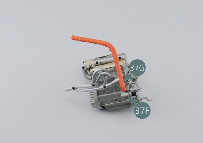
Connect the air duct #1 (37G) to the alternator (37F).
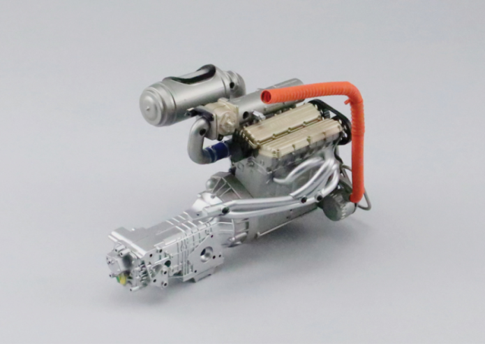
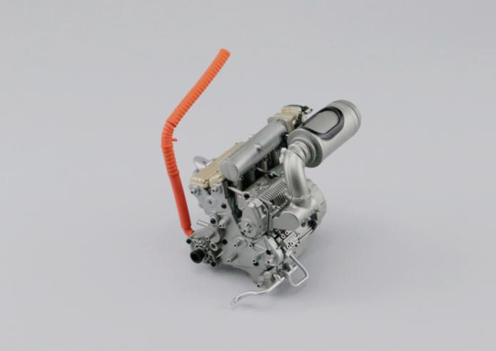
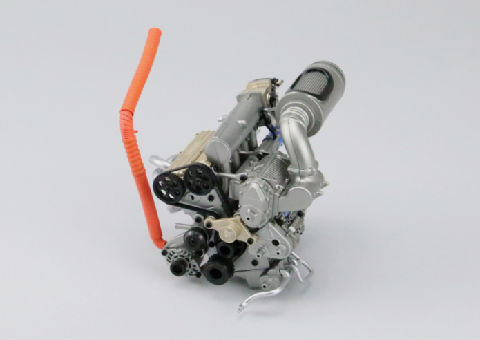
GENERAL VIEW
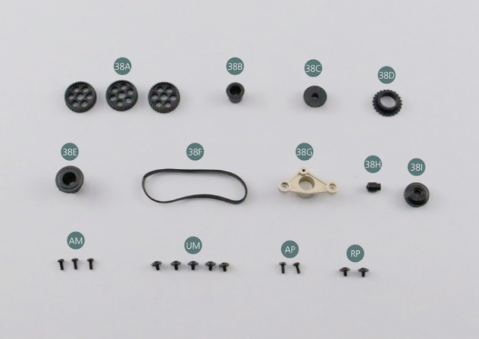
Kit 38 - TIMING BELT AND PULLEYS
Parts of kit
- 38A Pulley #12 (x 3)
- 38B Pulley #10
- 38C Pulley #11
- 38D Pulley #4
- 38E Pulley #1
- 38F Belt #1
- 38G Pulley #3 and bracket
- 38H Pulley #6
- 38I Pulley #5
- Screw AM M 1.7 x 4 mm (x 3)
- Screw UM M 1.7 x 3 mm (x 5)
- Screw AP P 1.7 x 4 mm (x 2)
- Screw RP P 1.7 x 3 mm (x 2)
Step 1
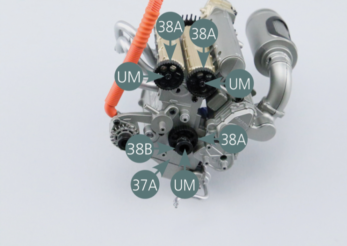
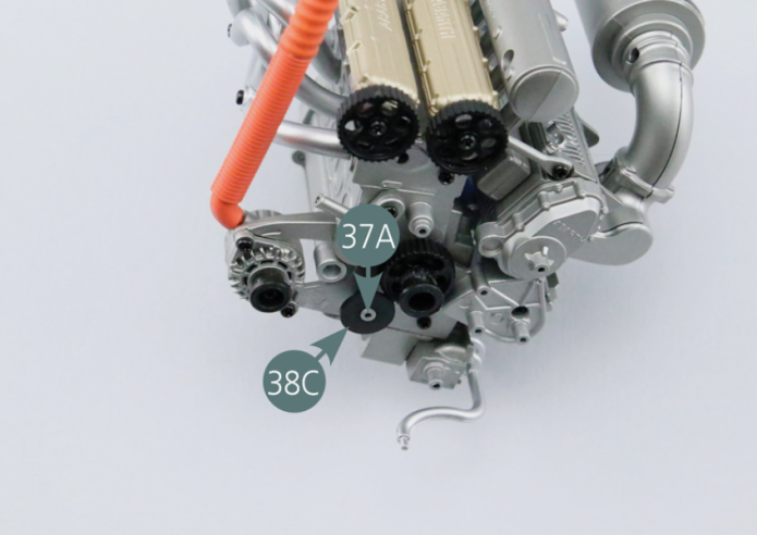
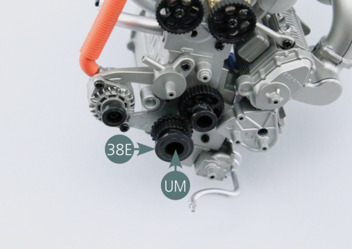
Position the two upper pulleys (38A) on the front of the motor (37A) and secure with two UM screws. Position the lower pulley (38A) on the front of the engine (37A) and insert the pulley #10 (38B). Secure the two pulleys (38A&38B) to the front of the engine (37A) with an UM screw. Place the pulley #11 (38C) on the axle located at the bottom of the front of the engine (37A).
Step 2
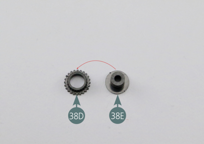
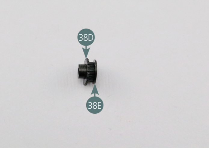
Place the pulley #4(38D) on the pulley #1 (38E) as indicated in the picture. Position the pulley assembly (38D&38E) on the pulley #11 (38C) and secure them with a UM screw.
Step 3
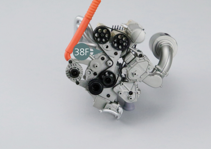
Position the timing belt (38F) as shown in the picture.
Step 4
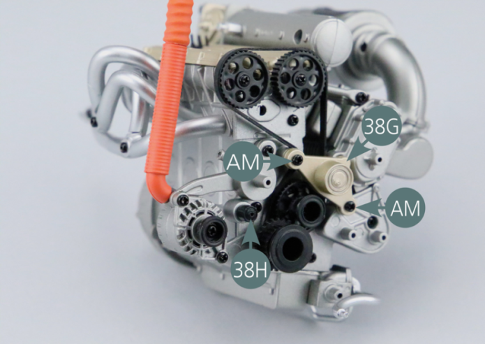
Position the pulley #3 (38G) and secure with two AM screws. Position the pulley #6 (38H) and secure it from the rear with an AP screw.
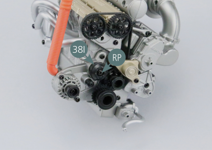
Step 5
Position the pulley #5 (38I) and secure it with an RP screw.
GENERAL VIEW
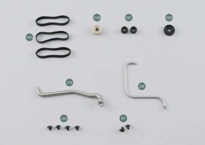
Kit 39 - OTHER ENGINE BELTS
Parts of kit
- 39A Belt #2 (x 3)
- 39B Pulley #8
- 39C Pulley #9 (x 2)
- 39D Pulley #2
- 39E Water hose #1
- 39F Water hose #2
- Screw UM M 1.7 x 3 mm (x 4)
- Screw RP P 1.7 x 3 mm (x 2)
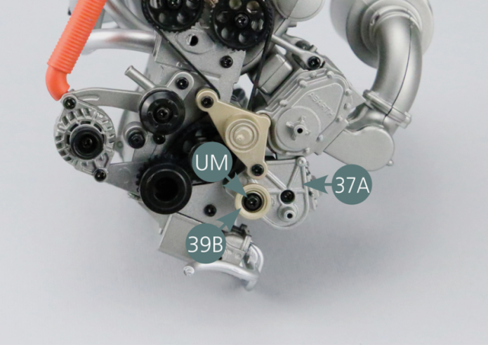
Step 1
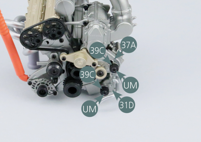
Place the pulley #8 (39B) on the front of the engine (37A) and secure it with a UM screw.
Step 2
Position the two pulleys #9 (39C) on the front of the engine (37A) and on the oil pump (31D), then secure each of them with a UM screw.
Step 3
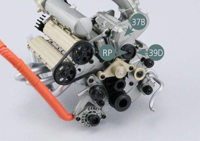
Position the pulley #2 (39D) on the bracket of the turbocharger pulley (37B) and secure with an RP screw.
Step 4
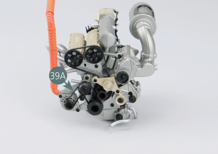
Position the first belt #2 (39A) as shown in the picture.
Step 5
Position the second belt #2 (39A) as shown in the picture.
Step 6
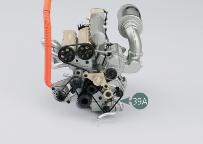
Position the third belt #2 (39A) as shown in the picture.
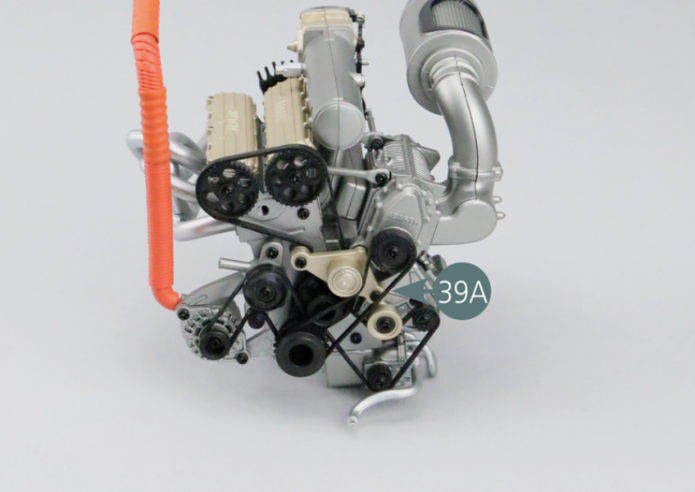
Step 7
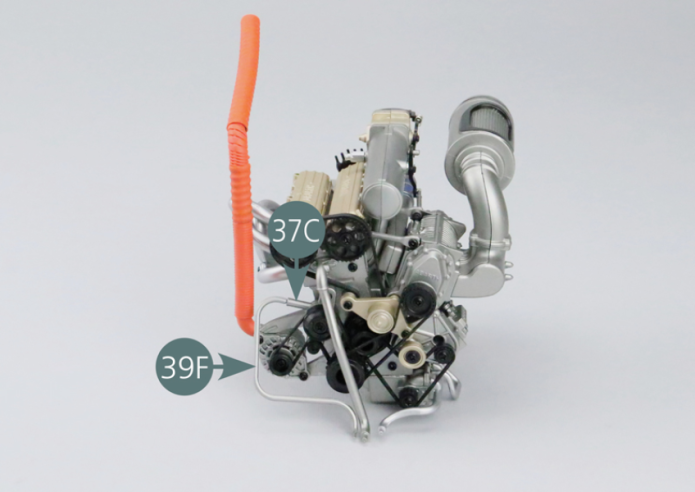
Position the water hose #1 (39E) on the front of the engine (37A).
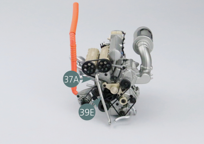
Step 8
Position the water hose #2 (39F) on the front of the engine (37C).
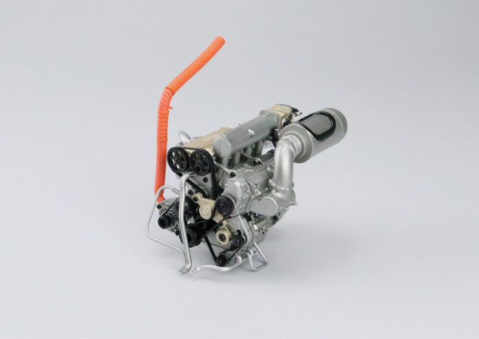
GENERAL VIEW
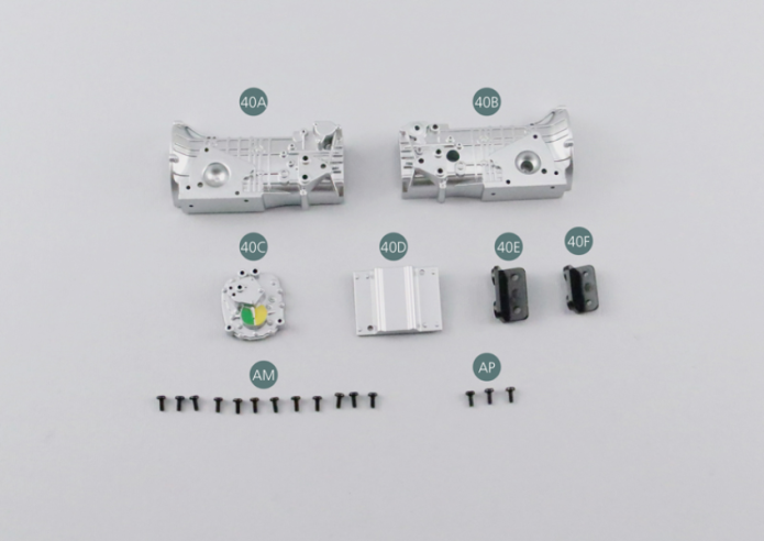
Kit 40 - GEARBOX
Parts of kit
- 40A Gearbox (left side)
- 40B Gearbox (right side)
- 40C Gearbox (rear)
- 40D Air box (bottom)
- 40E Clutch joint
- 40F Rear joint
- Screw AM M 1.7 x 4 mm (x 12)
- Screw AP P 1.7 x 4 mm (x 3)
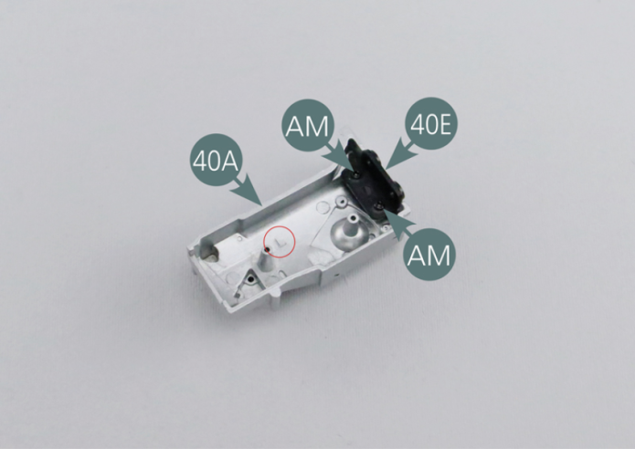
Step 1
Place the clutch joint(40E) on the left gearbox (40A) (marked with the letter L) and secure with two AM screws.
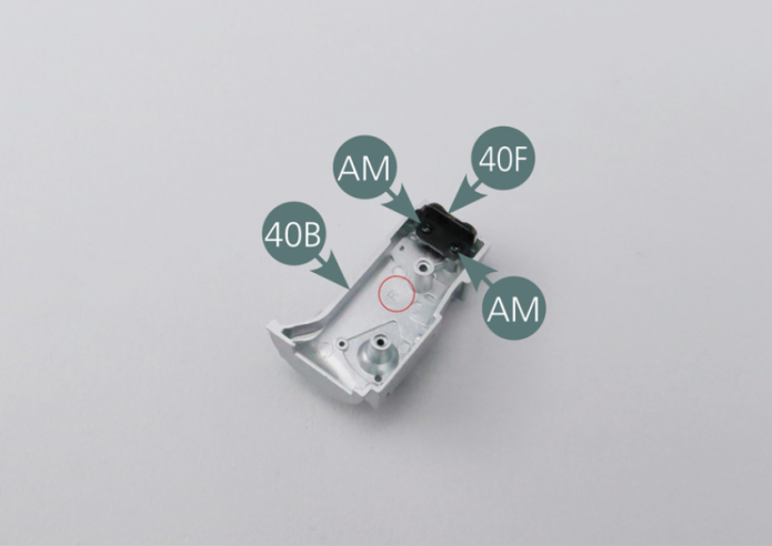
Step 2
Place the rear joint (40F) on the right gearbox (40B) (marked with the letter R) and secure with two AM screws.
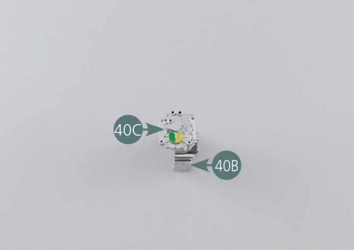
Step 3
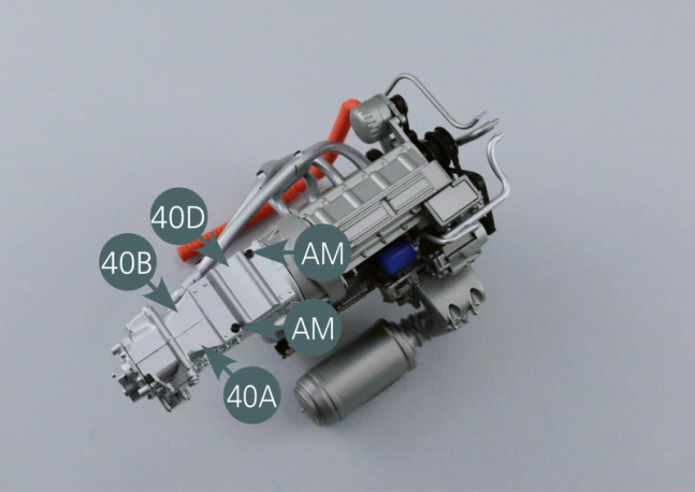
Position the rear of the gearbox (40C) on the right gearbox (40B) as indicated in the picture and secure with two AP screws.
Step 4
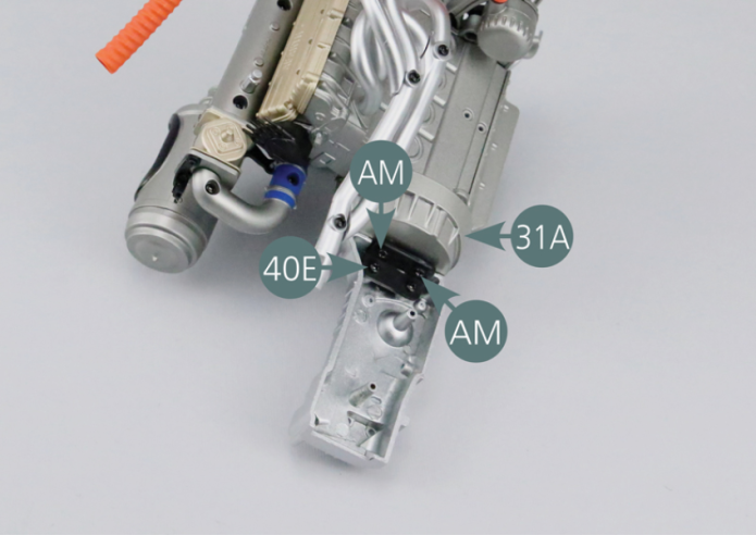
Position the clutch joint (40E) on the gearbox housing (31A) and secure it with two AM screws. Close the gearbox with the right part (40B) and secure it with two AM screws.
Step 5
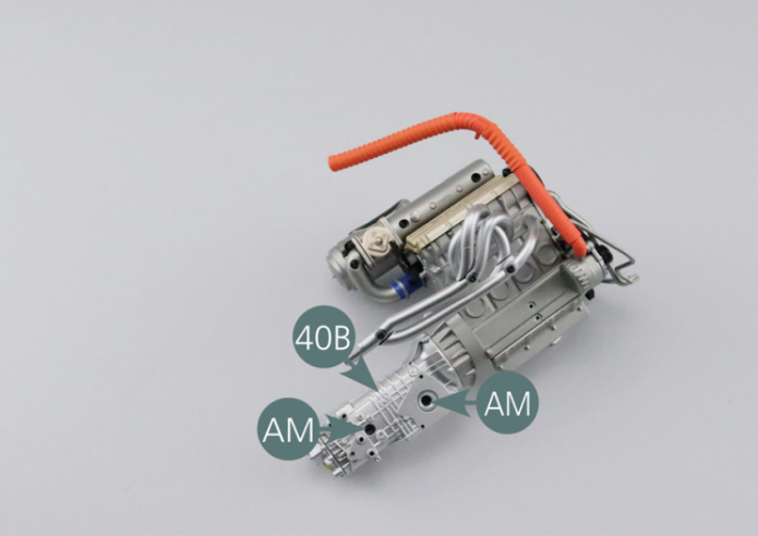
Place the bottom of the gearbox (40D) on the right and left parts (40B&40A) of the box and secure it with two AM screws.
GENERAL VIEW