English
 français
 Deutsch
 español
 italiano
 português


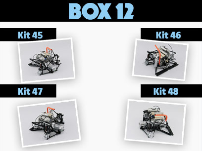
Box 12
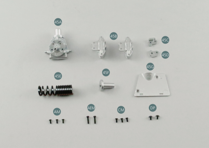
Parts of kit
- 45A Left rear hub
- 45B Brake caliper (x 2)
- 45C Left hinge #1
- 45D Left hinge #2
- 45E Rear suspension spring
- 45F Upper rear suspension spring bracket

Etape 1
- 45G Left rear suspension panel
- Screw AM M 1.7 x 4 mm (x 3)
- Screw AEM M 2.0 x 8 mm (x 2)
- Screw CM M 2.0 x 4 mm (x 3)
- Screw DP P 2.0 x 4 mm (x 2)
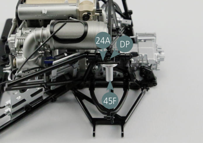
Positionner le support supérieur de ressort de suspension arrière 45F sous le bras de liaison arrière gauche 24A et le fixer avec une vis DP.
Etape 2
Position the upper rear suspension spring bracket (45F) beneath the left rear link arm (24A) and secure with a DP screw.

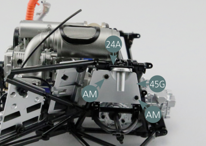
Positionner le panneau de suspension arrière gauche 45G sur le bras de liaison arrière gauche 24A et le fixer avec deux vis AM.

Etape 3
Position the left rear suspension panel (45G) on the left rear link arm (24A) and secure it with two AM screws.
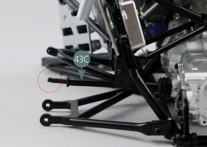
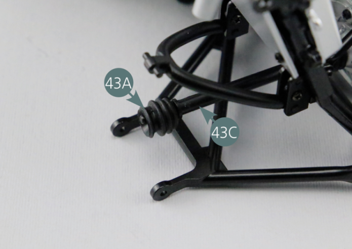
Vérifier le bon positionnement de l’arbre de transmission arrière gauche 43C, puis placer le soufflet d’arbre de transmission 43A à son extrémité.


Etape 4
Check that the left rear driveshaft (43C) is correctly positioned, then place the driveshaft bellows (43A) at its end.
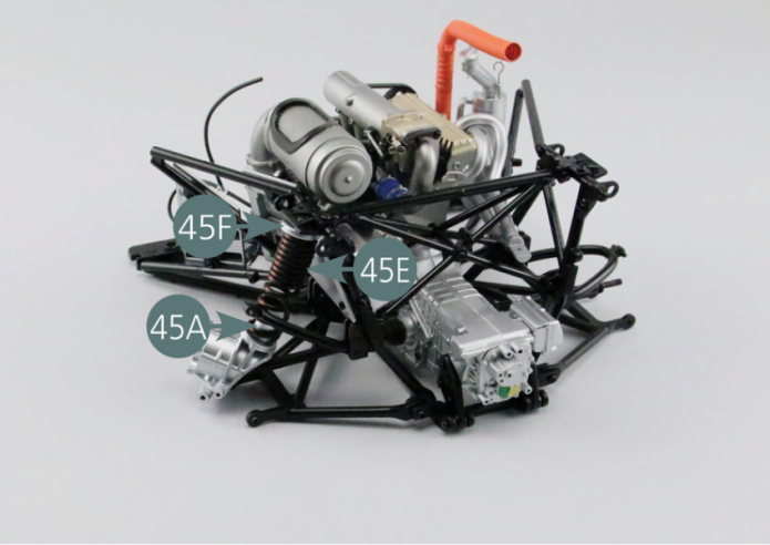
Positionner le ressort de suspension arrière 45E et le moyeu arrière gauche 45A comme indiqué sur la photo.
Etape 5
Position the rear suspension spring (45E) and the left rear hub (45A) as shown in the photo.

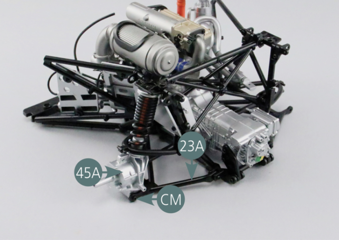
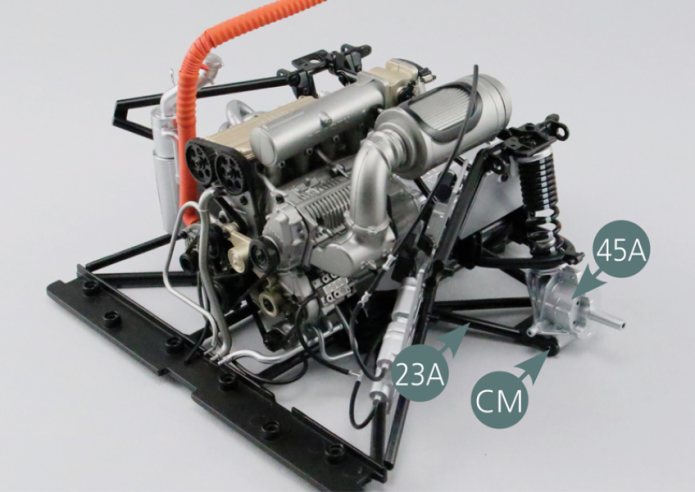
Fixer le moyeu arrière gauche 45A sur le bras de suspension inférieure arrière gauche 23A avec deux vis CM.

Etape 6
Secure the left rear hub (45A) to the left rear lower suspension arm (23A) using two CM screws.

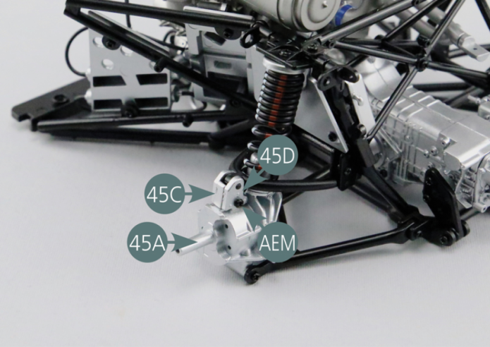
Positionner les deux charnières gauche 45C et 45D sur le moyeu arrière gauche 45A et les fixer avec une vis AEM.
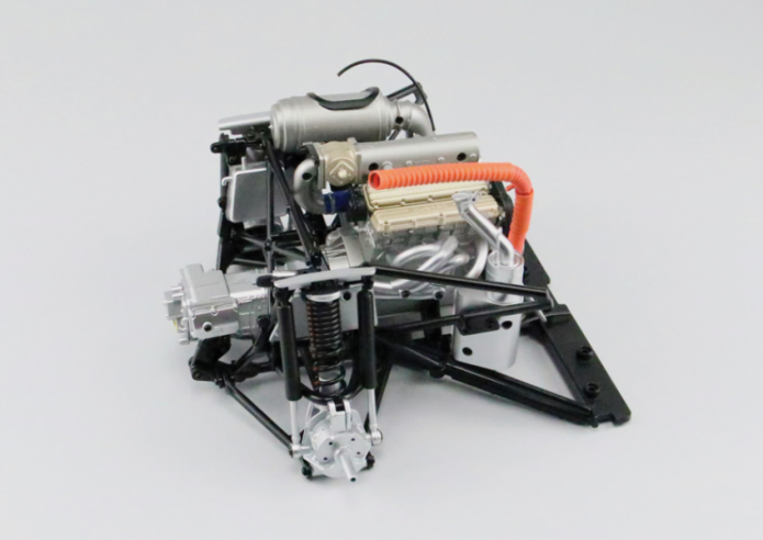
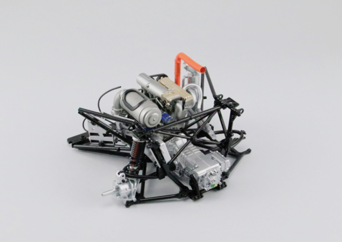
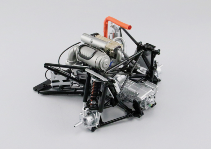
Vue générale
Position the two left hinges (45C&45D) on the left rear hub (45A) and secure them with an AEM screw.

GENERAL VIEW
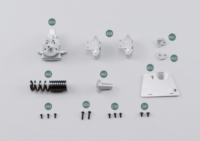
Parts of kit
Etape 1
- 46G Right rear suspension panel
- Screw AM M 1.7 x 4 mm (x 3)
- Screw AEM M 2.0 x 8 mm (x 2)
- Screw CM M 2.0 x 4 mm (x 3)
- Screw DP P 2.0 x 4 mm (x 2)
Positionner le panneau de suspension arrière droit 46G sur le bras de liaison arrière droit 25A et le fixer avec deux vis AM.

Etape 2
Position the right rear suspension panel (46G) on the right rear link arm (25A) and secure it with two AM screws.

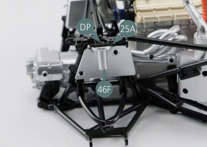
Positionner le support supérieur de ressort de suspension arrière 46F sous le bras de liaison arrière droit 25A et le fixer avec une vis DP.

Etape 3
Position the upper rear suspension spring bracket (46F) beneath the right rear link arm (25A) and secure with a DP screw.
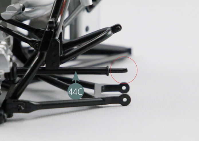
Vérifier le bon positionnement de l’arbre de transmission arrière droit 44C, puis placer le soufflet d’arbre de transmission 44A à son extrémité.

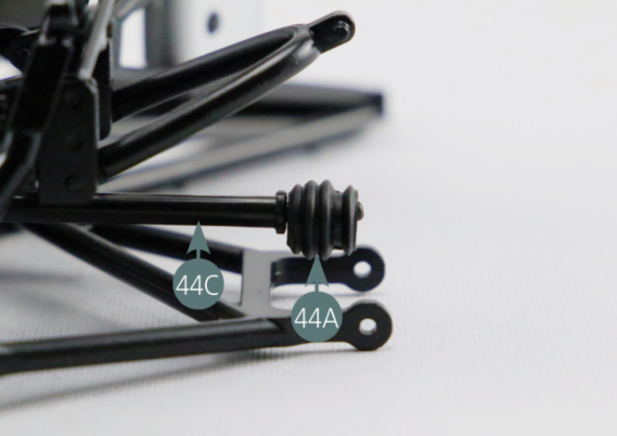
Etape 4
Check that the right rear driveshaft (44C) is correctly positioned, then place the driveshaft bellows (44A) at its end.

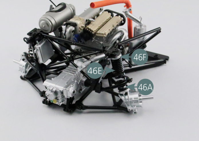
Positionner le ressort de suspension arrière 46E et le moyeu arrière droit 46A comme indiqué sur la photo.

Etape 5
Position the rear suspension spring (46E) and the right rear hub (46A) as shown in the photo.
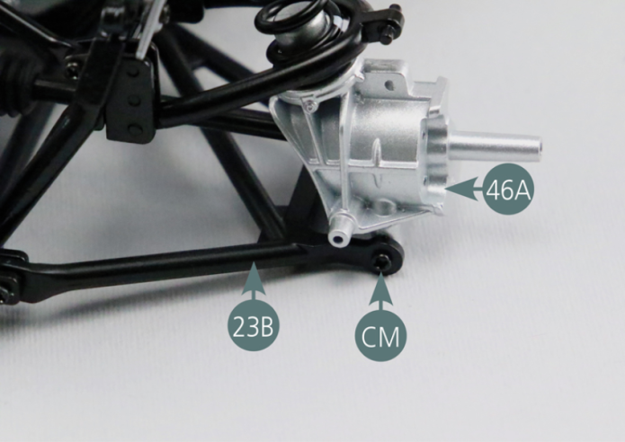
Fixer le moyeu arrière droit 46A sur le bras de suspension inférieure arrière droit 23B avec deux vis CM.

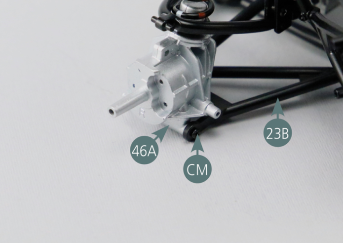
Etape 6
Secure the right rear hub (46A) to the right rear lower suspension arm (23B) using two CM screws.

Positionner les deux charnières droites 46C et 46D sur le moyeu arrière droit 46A et les fixer avec une vis AEM.
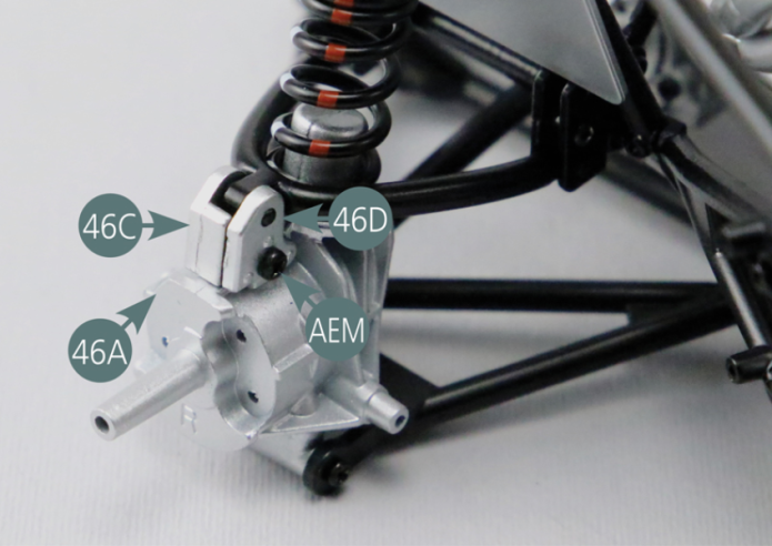
Vue générale
Position the two right hinges (46C&46D) on the r rear hub (46A) and secure them with an AEM screw.
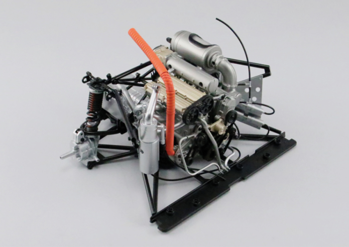
GENERAL VIEW
Parts of kit

Etape 1
- 47D Shock spring (x 2)
- Screw UM M 1.7 x 3 mm (x 3)
- Screw RP P 1.7 x 3 mm (x 2)
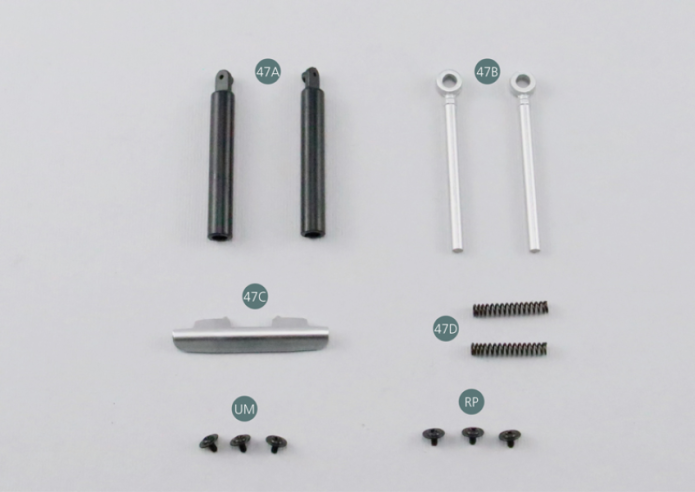
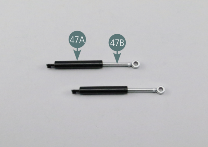
Insérer un ressort 47D puis un piston d’amortisseur 47B dans un cylindre d’amortisseur 47A.
Assemblez le deuxième amortisseur de la même manière.
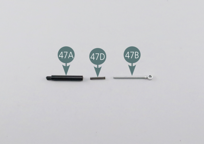
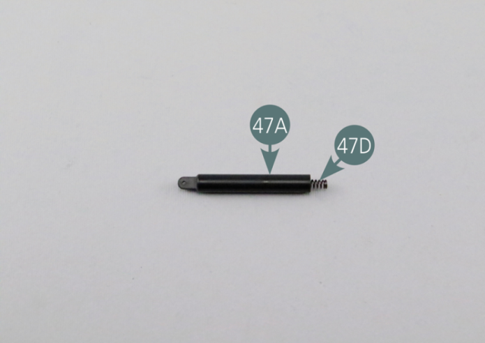
Introduce a spring (47D) and then a shock piston (47B) into a shock cylinder (47A). Assemble the second shock cylinder in the same way.

Etape 2

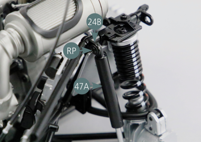
Positionner un amortisseur sur le côté gauche du berceau moteur. Fixer l’extrémité supérieure du cylindre d’amortisseur 47A sur le support de bras de liaison #1 24B avec une vis RP.
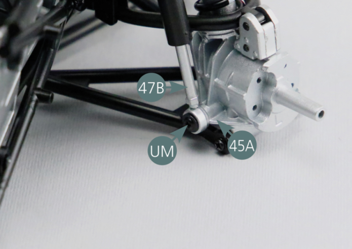
Fixer ensuite l’extrémité inférieure du piston d’amortisseur 47B sur le moyeu arrière gauche 45A avec une vis UM.
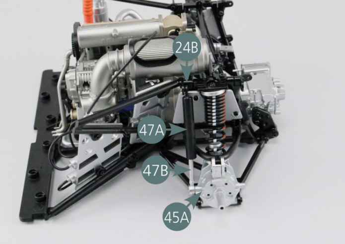

Position a shock absorber on the left side of the engine cradle. Secure the upper end of the shock absorber cylinder (47A) to the link arm bracket #1 (24B) using a RP screw. Then attach the lower end of the shock absorber piston (47B) to the left rear hub (45A) using a UM screw.

Etape 3
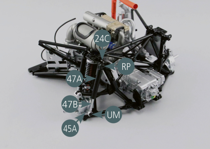
Positionner le second amortisseur sur le berceau moteur. Fixer l’extrémité supérieure du cylindre d’amortisseur 47A sur le support de bras de liaison #2 24C avec une vis RP.
Fixer ensuite l’extrémité inférieure du piston d’amortisseur 47B sur le moyeu arrière gauche 45A avec une vis UM.
Etape 4
Position the second shock absorber on the engine cradle. Fix the upper end of the shock absorber cylinder (47A) to the link arm support #2 (24C) using a RP screw.
Then secure the lower end of the shock absorber piston (47B) to the left rear hub (45A) using a UM screw.

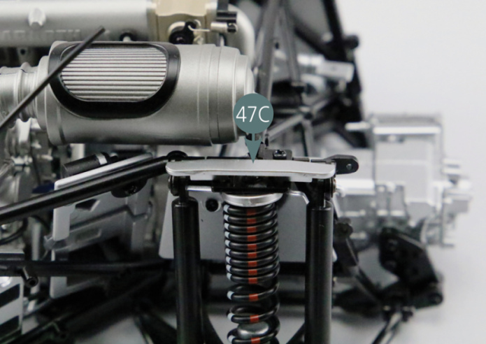
Positionner le cache-poussière supérieur 47C comme indiqué sur la photo.
Vue générale
Position the upper dust cover (47C) according to the photo.
GENERAL VIEW
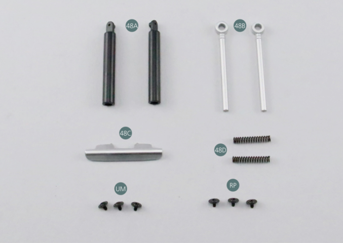
Parts of kit

Etape 1
- 48D Shock spring (x 2)
- Screw UM M 1.7 x 3 mm (x 3)
- Screw RP P 1.7 x 3 mm (x 2)
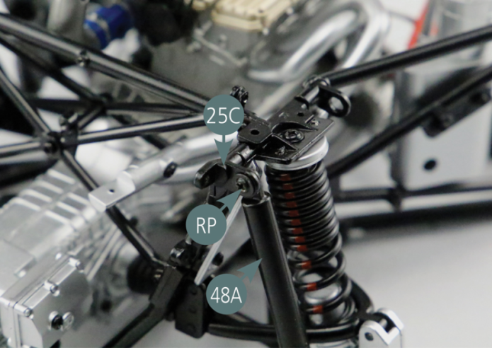
Après avoir assemblé les deux amortisseurs comme précédemment (voir étape 47- 1), positionner le premier d’entre eux sur le côté droit du berceau moteur.
Fixer l’extrémité supérieure du cylindre d’amortisseur 48A sur le support de bras de liaison #2 25C avec une vis RP.
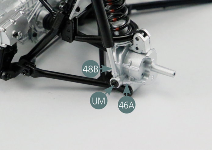
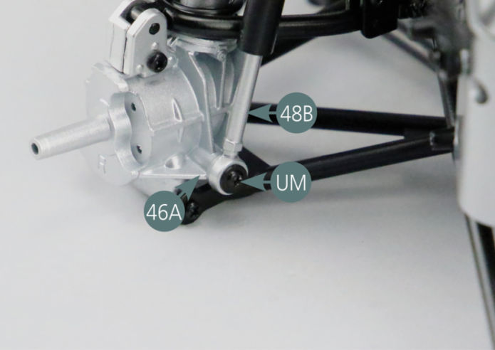
Fixer ensuite l’extrémité inférieure du piston d’amortisseur 48B sur le moyeu arrière gauche 46A avec une vis UM.
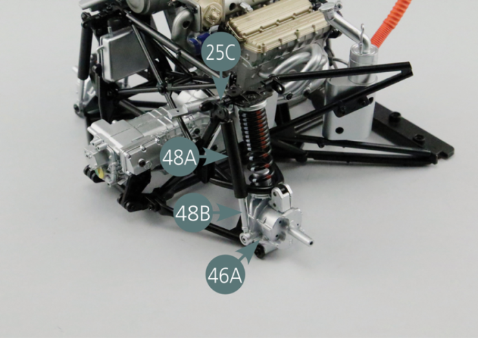

Having assembled the two shock absorbers as described above (see step 47- 1), place the first shock absorber on the right side of the engine cradle. Fix the upper end of the shock absorber cylinder (48A) to the link arm support #2 (25C) using an RP screw. Then attach the lower end of the shock absorber piston (48B) to the left rear hub (46A) using a UM screw.
Etape 2

Positionner le second amortisseur sur le berceau moteur. Fixer l’extrémité supérieure du cylindre d’amortisseur 48A sur le support de bras de liaison #2 25B avec une vis RP.
Fixer ensuite l’extrémité inférieure du piston d’amortisseur 48B sur le moyeu arrière gauche 46A avec une vis UM.
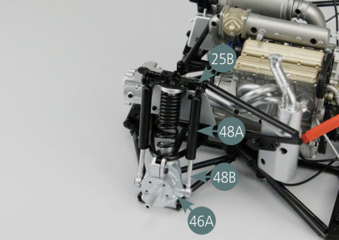
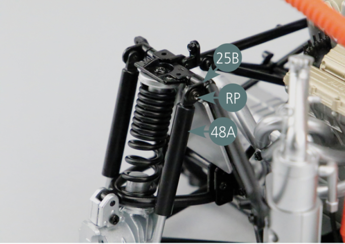
Position the second shock absorber on the engine cradle. Fix the upper end of the shock absorber cylinder (48A) to the link arm support #1 (25B) using a RP screw. Then attach the lower end of the shock absorber piston (48B) to the left rear hub (46A) using a UM screw.
Etape 3


Positionner le cache-poussière supérieur 48C comme indiqué sur la photo.
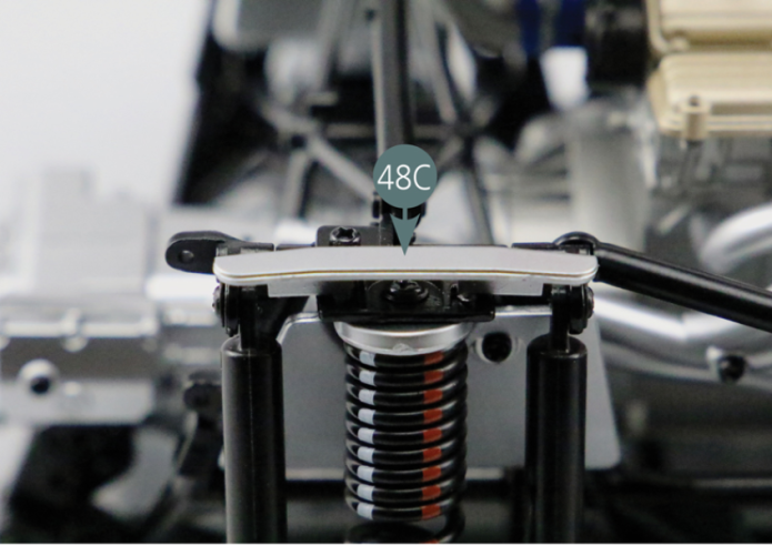
Vue générale
Position the upper dust cover (48C) according to the photo.