English
 français
 Deutsch
 español
 italiano
 português


Box 2
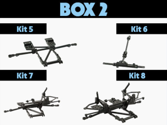
Kit 5 - ASSEMBLY OF LOWER FRAME AND LOWER SUSPENSION ARMS
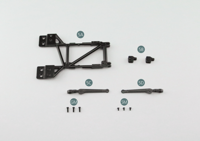
Parts of kit
- 5A Lower frame
- 5B Mounting bracket (x 2)
- 5C Lower left suspension arm
- 5D Lower right suspension arm
- SM Screw M 1.7 x 3 mm (x 3)
- Screw GM M 2.0 x 6 mm (x 3)
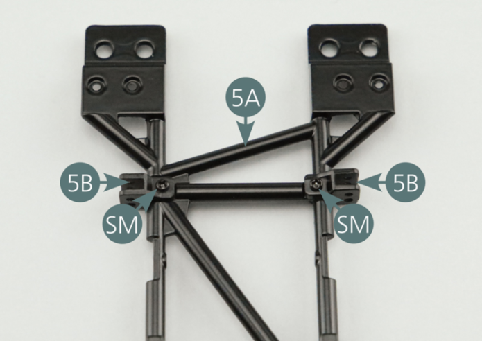
Step 1
Position the two mounting brackets (5B) on the lower frame (5A) and secure each with a SM screw.
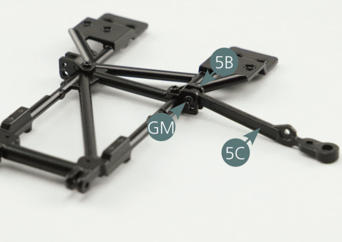
Step 2
Place the left lower suspension arm (5C) on the mounting bracket (5B) located on the left side of the frame (5A) and fasten with a GM screw.
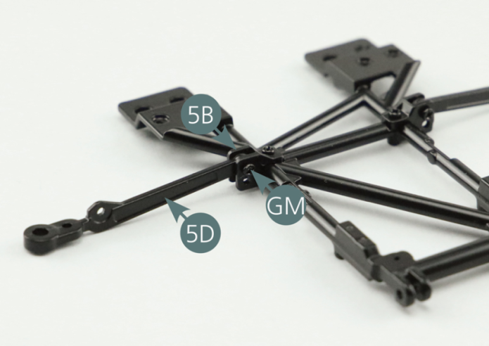
Step 3
Position the lower right suspension arm (5D) on the mounting bracket (5B) located on the right side of the frame (5A) and secure with a GM screw.
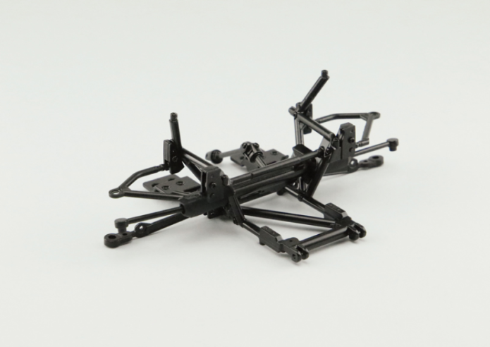
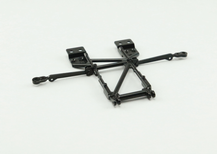
GENERAL VIEW
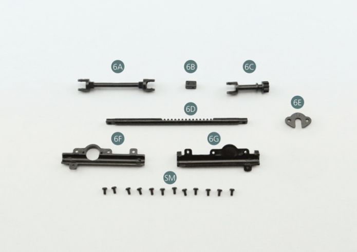
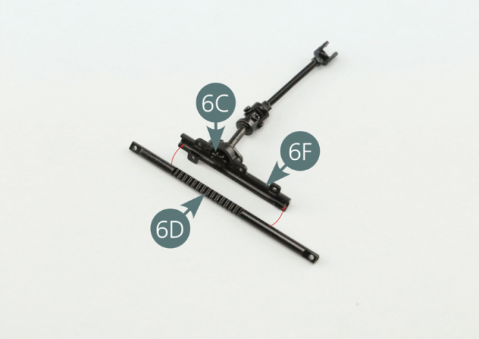
Kit 6 - STEERING COLUMN ASSEMBLY
Parts of kit
- 6A Intermediate shaft
- 6B Universal joint
- 6C Steering pinion
- 6D Steering rack
- 6E Flange
- 6F Steering rack half-column
- 6G Steering rack half-column
- Screw SM M 1.7 x 3 mm (x 12)
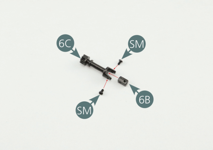
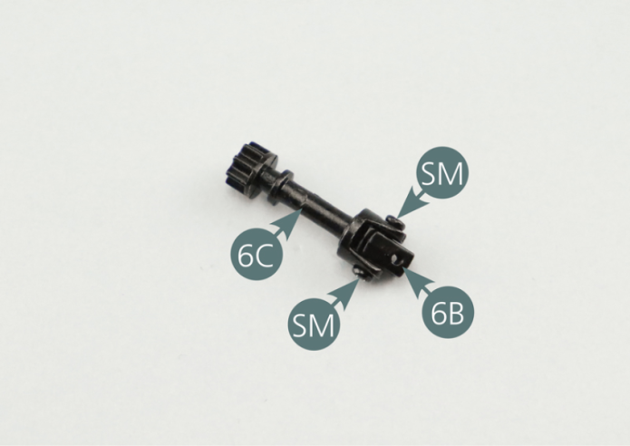
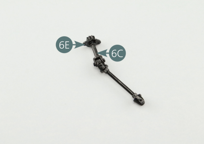
Step 1
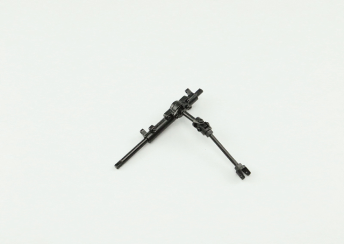
Position the universal joint (6B) on the steering pinion (6C) and fix it with two SM screws.
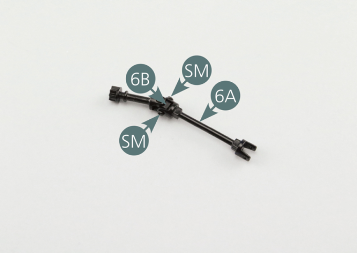
Step 2
Position the intermediate shaft (6A) on the universal joint (6B) and secure with two SM screws.
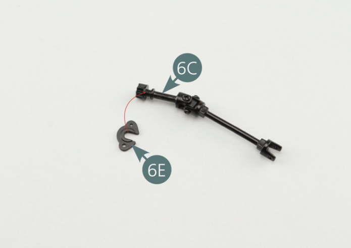
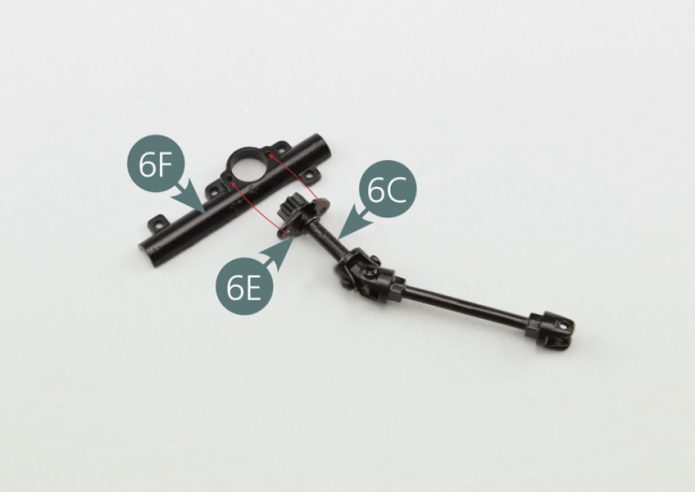
Step 3
Position the flange (6E) on the steering pinion (6C).
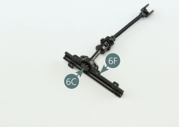
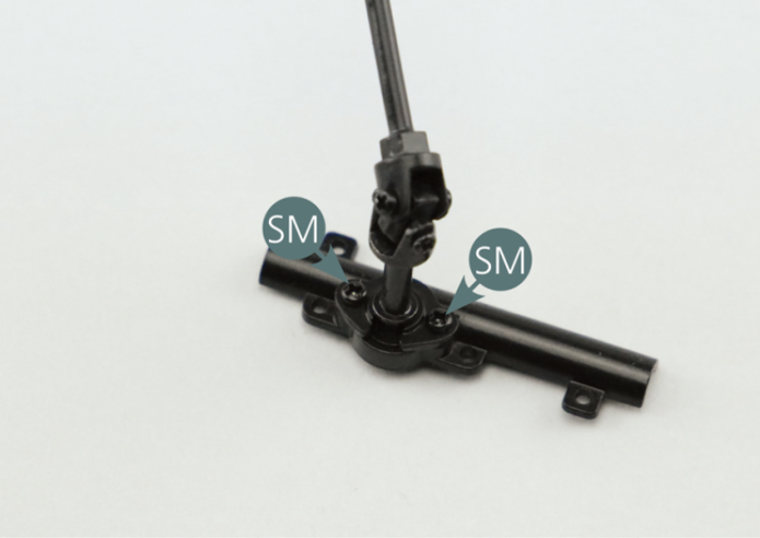
Step 4
Position the flange (6E) on the rack half-column (6F) and secure it with two SM screws.
Step 5
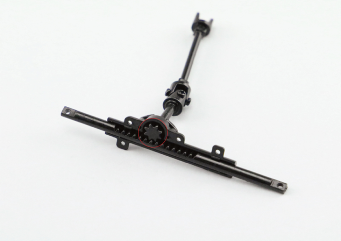
Place the steering rack (6D) into the rack half column (6F) making sure to place the steering pinion (6C) in the middle of the rack's toothed section - red circle.
Step 6
Position the steering rack column half (6G) on the steering rack column half (6F) including the steering rack (6D) and secure it with four SM screws.

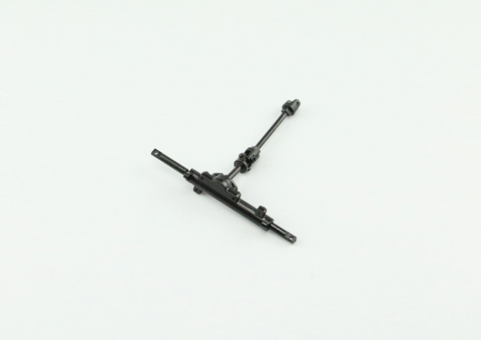
GENERAL VIEW
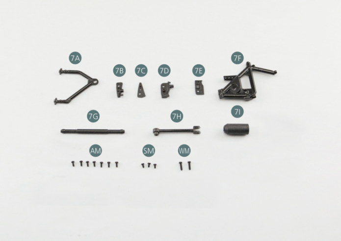
Kit 7 - ASSEMBLY OF THE LEFT SUSPENSION
Parts of kit
- 7A Upper left suspension arm
- 7B Bracket
- 7C Support bracket
- 7D Bracket
- 7E Support bracket
- 7F Side frame left
- 7G Steering arm
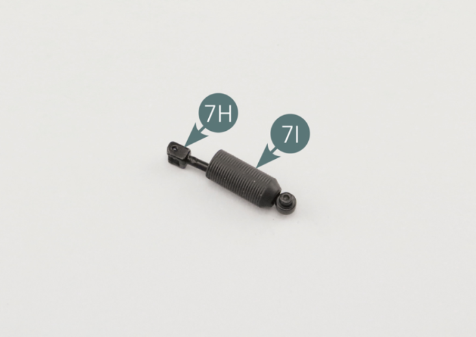
- 7H Steering tie-rod
- 7I Bellow
- Screw AM M 1.7 x 4 mm (x 7)
- Screw SM M 1.7 x 3 mm (x 3)
- Screw WM M 2.0 x 7 mm (x 2)
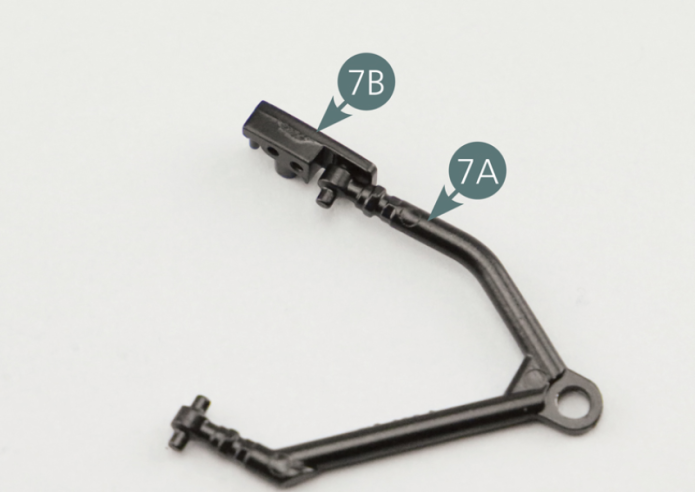
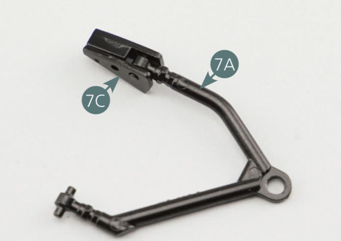
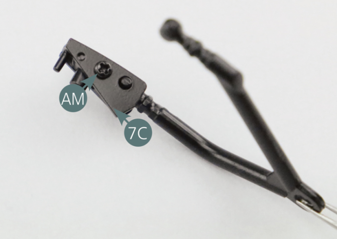
Step 1
Position the bracket (7B) and support bracket (7C) on the rear pivot of the upper left suspension arm (7A) and secure with an AM screw.
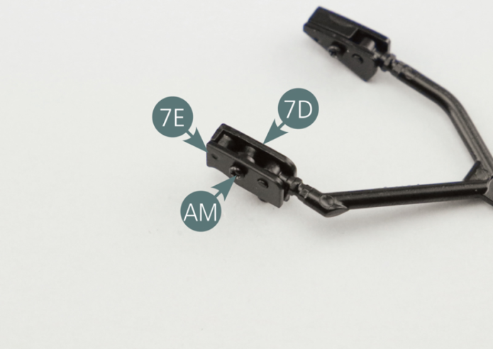
Step 2
Position the bracket (7D) and support bracket (7E) on the front pivot of the upper left suspension arm (7A) and secure with an AM screw.
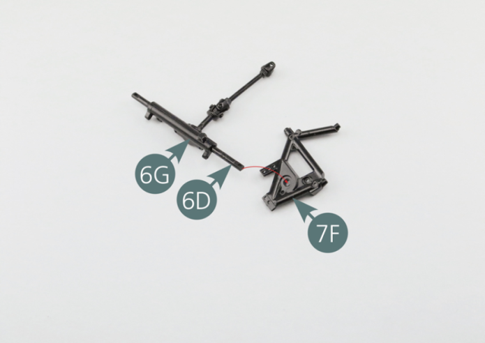
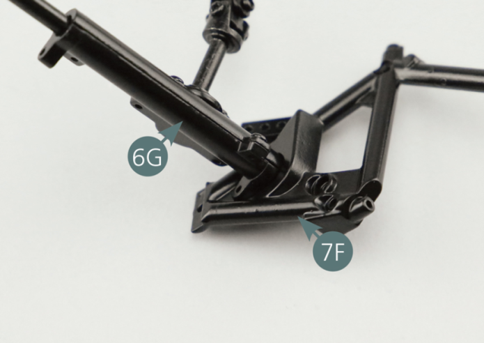
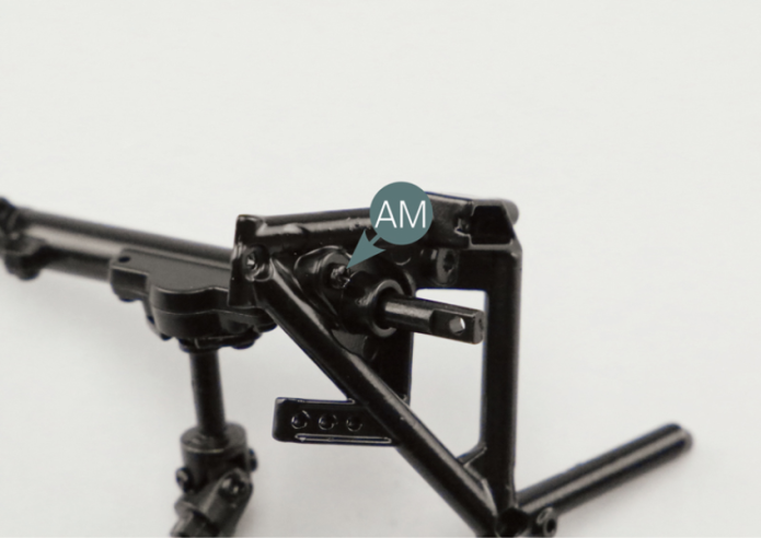
Step 3
Position the steering rack column (6G) on the left side chassis frame (7F), passing the steering rack (6D) through the opening provided, then secure it with an AM screw.
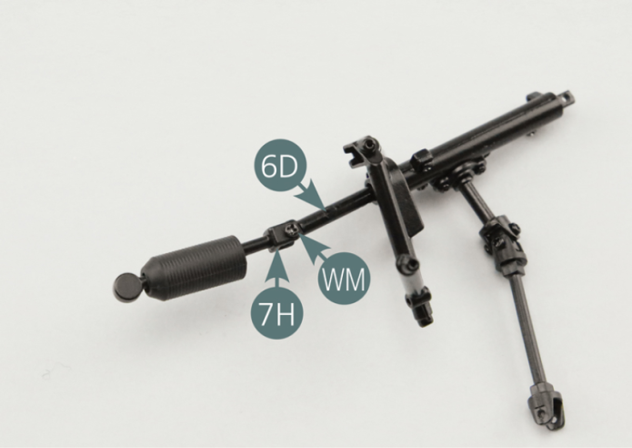
Step 4
Slide the steering tie rod (7H) into the bellow (7I) and secure to the steering rack (6D) using a WM screw. Slide the bellow (7I) to cover the end of the steering rack.
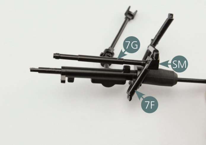
Step 5
Position the steering arm (7G) on the left side frame (7F) and secure with a SM screw.
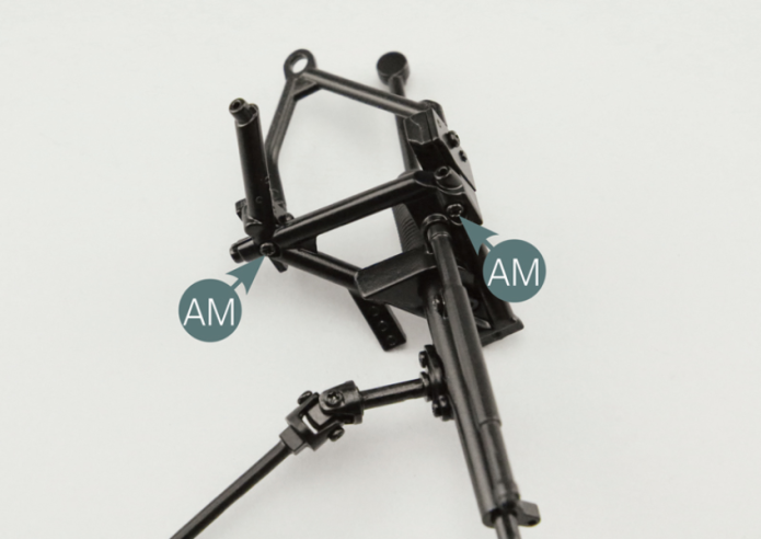
Step 6
Position the brackets (7B & 7D) carrying the upper left suspension arm (7A) onto the left side frame (7F) and secure them with two AM screws.

Step 7
Position the left side frame (7F) on the lower frame (5A) and secure it with an SM screw.

GENERAL VIEW
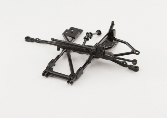
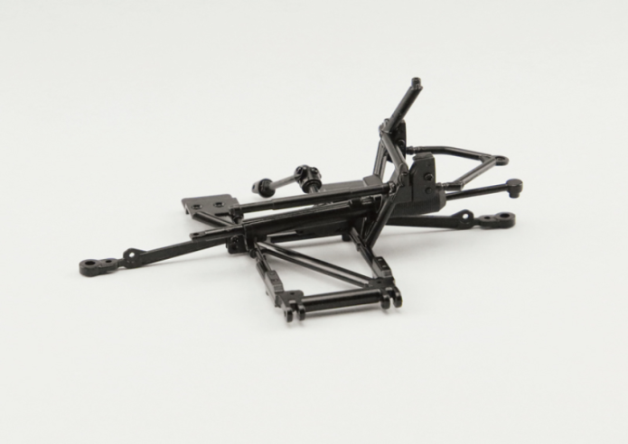
Kit 8 - ASSEMBLY OF THE RIGHT SUSPENSION
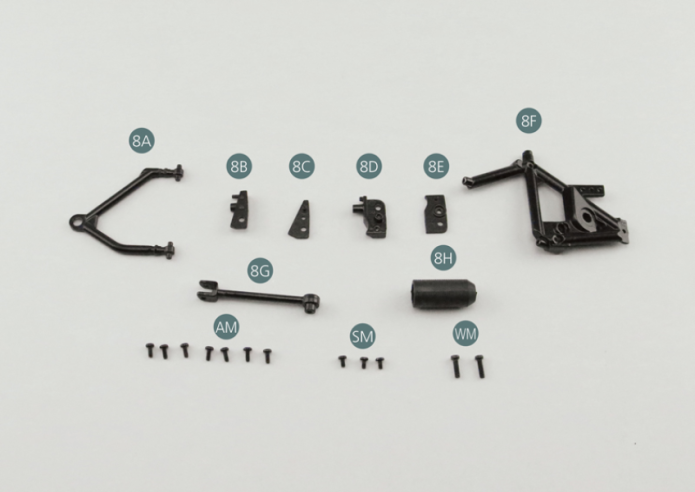
Parts of kit
- 8A Upper right suspension arm
- 8B Bracket
- 8C Support bracket
- 8D Bracket
- 8E Support bracket
- 8F Side frame right
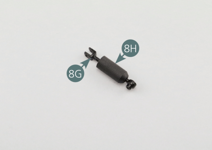
- 8G Steering arm
- 8H Steering tie-rod
- 8I Bellow
- Screw AM M 1.7 x 4 mm (x 7)
- Screw SM M 1.7 x 3 mm (x 3)
- Screw WM M 2.0 x 7 mm (x 2)
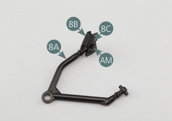
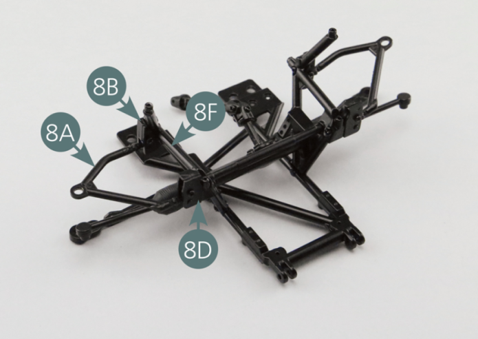
Step 1
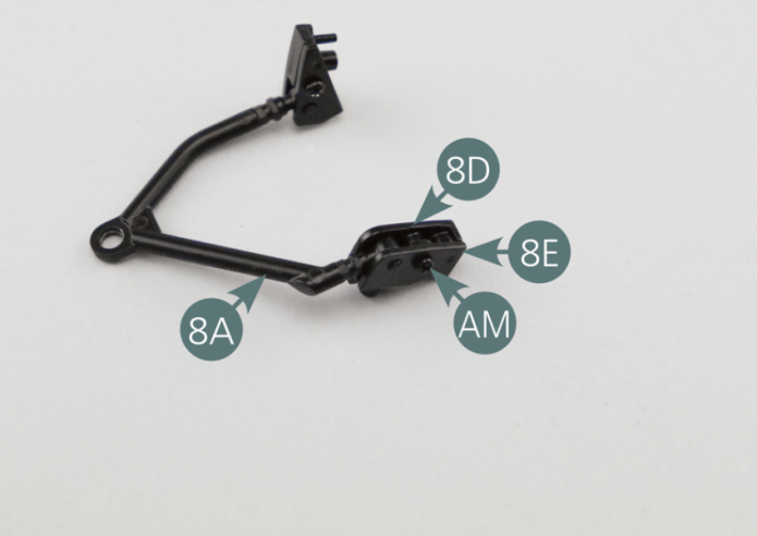
Position the bracket (8B) and support bracket (8C) on the rear pivot of the upper right suspension arm (8A) and secure with an AM screw.
Step 2
Position the support (8D) and support bracket (8E) on the front pivot of the upper right suspension arm (8A) and secure with an AM screw.
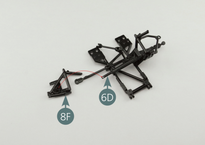
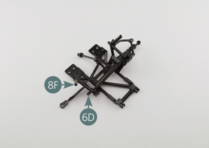
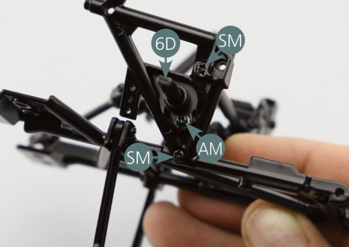
Step 3
Position the steering rack casing (6F+6G) on the right side frame (8F) of the chassis, inserting the steering rack (6D) in the appropriate opening; then secure part 1 6G of the steering rack casing with an AM screw. At the same time, position the right side frame (8F) and steering damper (7G) on the bottom frame (5A) and secure with two SM screws.
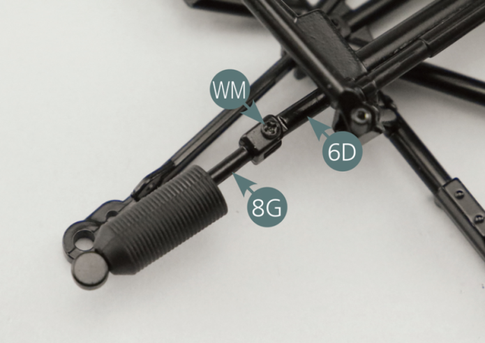
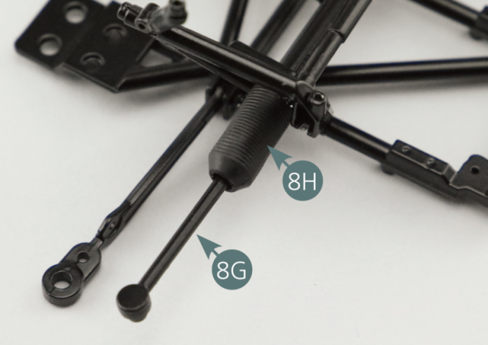
Step 4
Insert the steering arm (8G) into the bellow (8H) and secure it to the steering rack (6D) using a WM screw. Slide the steering tie-rod (8H) inwards to cover the end of the steering rack.
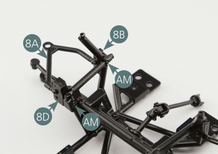
Step 5
Position brackets 1 and 3 (8B & 8D) on the right side frame (8F) and secure with two AM screws.
Vue générale