English
 français
 Deutsch
 español
 italiano
 português


Box 25
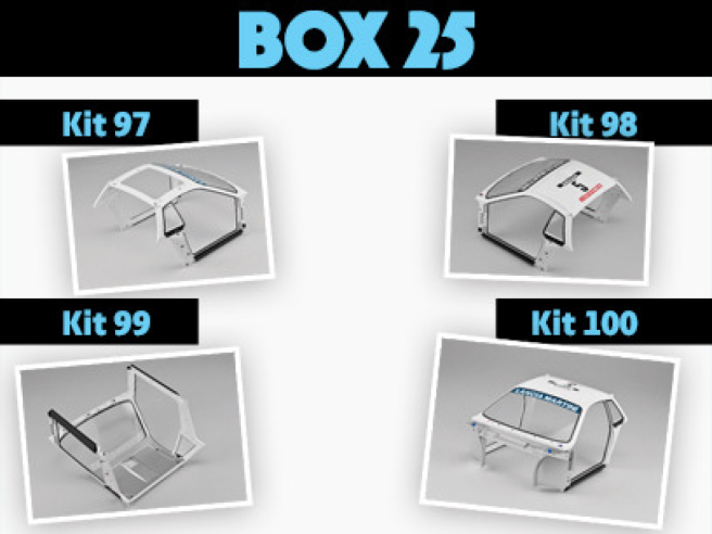
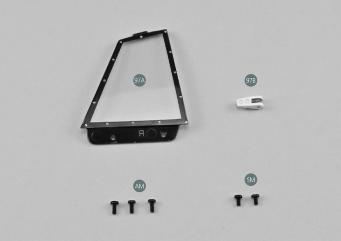
Parts of kit
- 97A Right rear quarter window
- 97B Upper right rear hinge
Etape 1
- Screw AM M 1.7 x 4 mm (x 3)
- Screw SM M 1.7 x 3 mm (x 2)

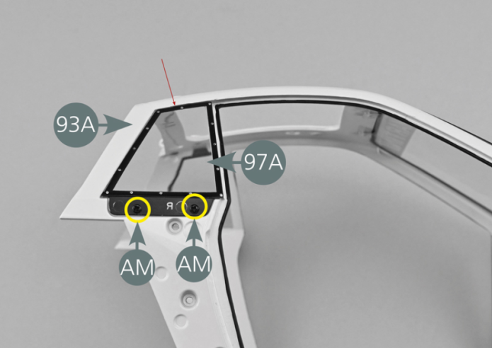
Positionner la glace de custode arrière droite 97A sur la carrosserie centrale 93A en insérant d’abord la partie supérieure (flèche rouge), puis fixer la glace avec deux vis AM sur la partie inférieure (cercles jaunes).

Etape 2
Position the right rear quarter window (97A) on the central body (93A) by first inserting the upper part (red arrow), then secure the window with two AM screws on the lower part (yellow circles).
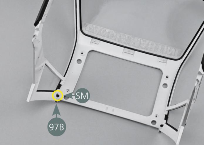
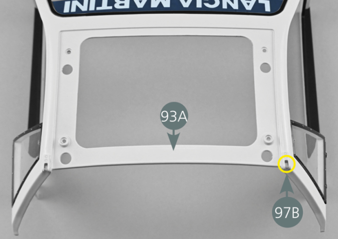
Positionner la charnière supérieure arrière droite 97B dans le trou situé sur l’extérieur supérieur gauche de la carrosserie 93A (cercle jaune). En la maintenant, la fixer ensuite depuis l’intérieur de la carrosserie avec une vis SM comme indiqué sur la photo.

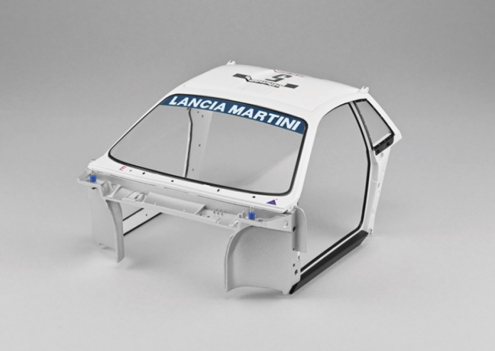
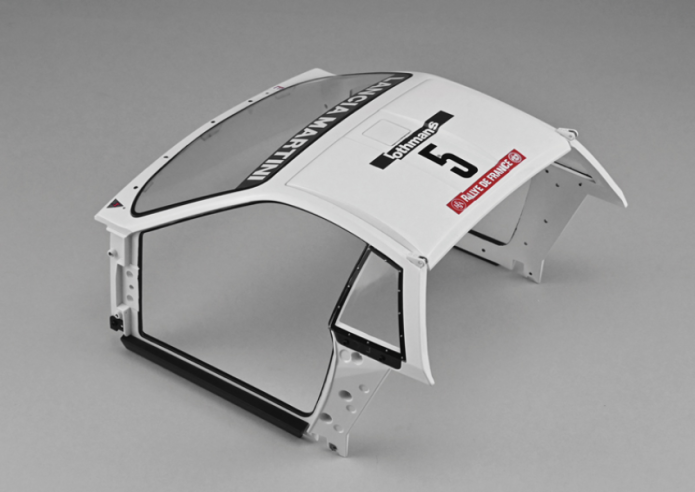
Vue générale
Position the right rear upper hinge (97B) in the opening located on the left upper exterior of the central body (93A) (yellow circle). Keeping it in place, then secure from the inside of the body with an SM screw as shown in the photo.
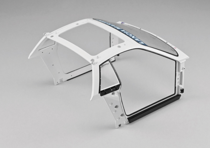
GENERAL VIEW
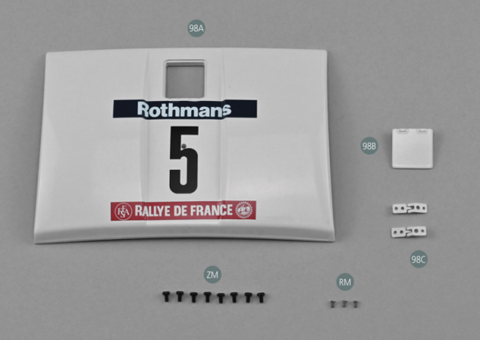
Parts of kit

Etape 1
- Screw ZM M 1.7 x 3 mm (x 8)
- Screw RM M 1.2 x 2 mm (x 3)
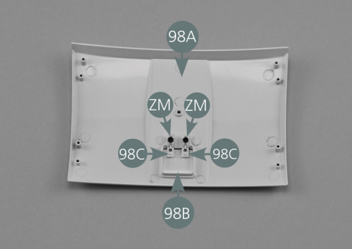
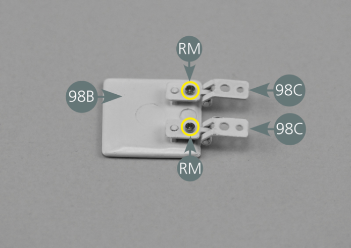
Positionner les charnières 98C sur la face intérieure de la trappe de toit 98B et les fixer chacune avec une vis RM. Positionner la trappe d’air 98B sur la face extérieure du panneau de toit 98A et la fixer par en dessous avec deux vis ZM placées sur les charnières 98C.

Etape 2
Position the hinges (98C) on the inside of the roof air intake (98B) and secure each with one RM screw. Position the air intake (98B) on the outside of the roof panel (98A) and secure it from below with two ZM screws placed on the hinges (98C).

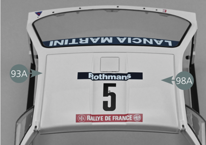
Positionner le panneau de toit 98A sur la carrosserie centrale 93A comme indiqué, puis retourner l’ensemble et fixer le panneau depuis l’intérieur avec quatre vis ZM (cercles jaunes).

Vue générale
Position the roof panel (98A) on the central body (93A) as shown, then turn the assembly over and secure the panel from the inside with four ZM screws (yellow circles).

GENERAL VIEW
Parts of kit

Etape 1
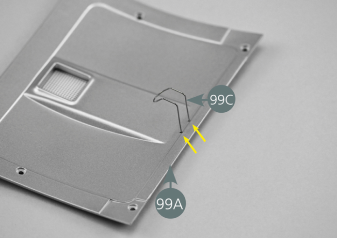
- 99C Helmet hook
- Screw SM M 1.7 x 3 mm (x 5)
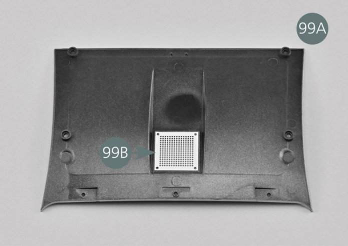
Placer le panneau intérieur du toit 99A, face interne vers le haut. Positionner la grille 99B sur l’ouverture carrée.
Positionner le crochet 99C comme indiqué, en l’enfonçant dans les deux trous prévus à cet effet (flèches jaunes).


Etape 2
Place the inner roof panel (99A), the inner side up. Position the grille (99B) on the square opening. Position the hook (99C) as shown, pushing it into the two openings provided for this purpose (yellow arrows).
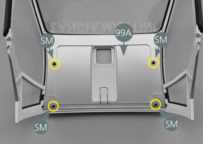
Retourner la partie centrale de la carrosserie 93A, positionner le panneau intérieur du toit 99A et le fixer avec quatre vis SM comme indiqué (cercles jaunes).
Vue générale
Turn over the central body part (93A), position the inner roof panel (99A) and secure it with four SM screws as shown (yellow circles).
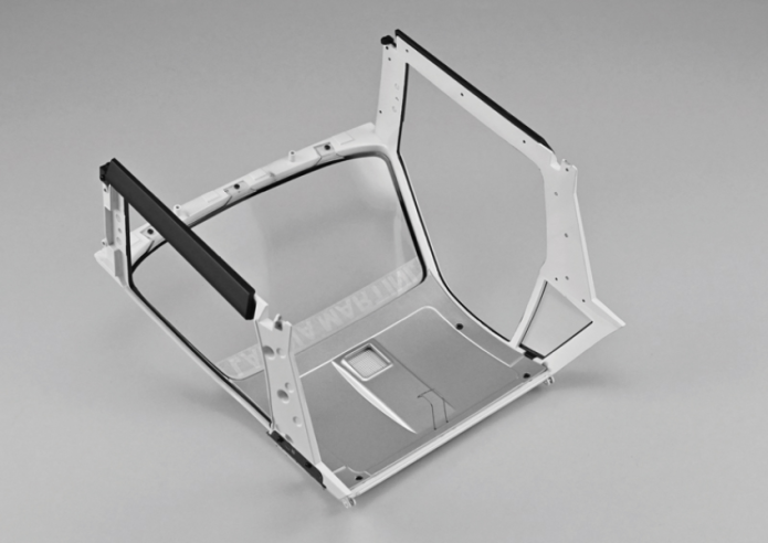
GENERAL VIEW
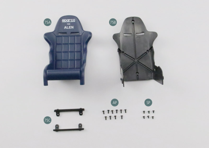
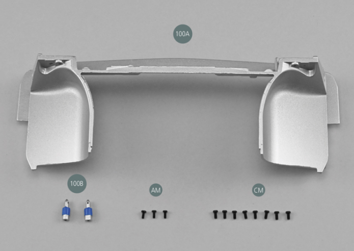
Parts of kit

Etape 1
- Screw AM M 1.7 x 4 mm (x 3)
- Screw CM M 2.0 x 4 mm (x 8)
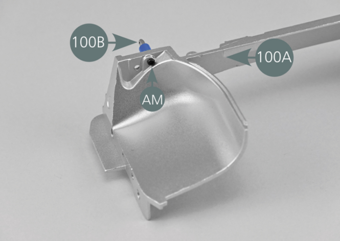
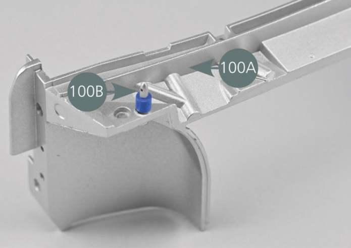
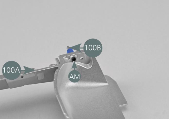
Positionner un support de capot avant 100B dans le trou situé au-dessus de la cloison d’habitacle avant 100A comme indiqué sur la photo, puis le fixer par l’arrière avec une vis AM.

Etape 2
Position one support front hood (100B) into the opening located above the front compartment bulkhead (100A) as shown in the photo, then secure it from the rear with an AM screw.

Positionner le second support de capot avant 100B dans le trou situé au-dessus de la cloison d’habitacle avant 100A, puis le fixer par l’arrière avec une vis AM.
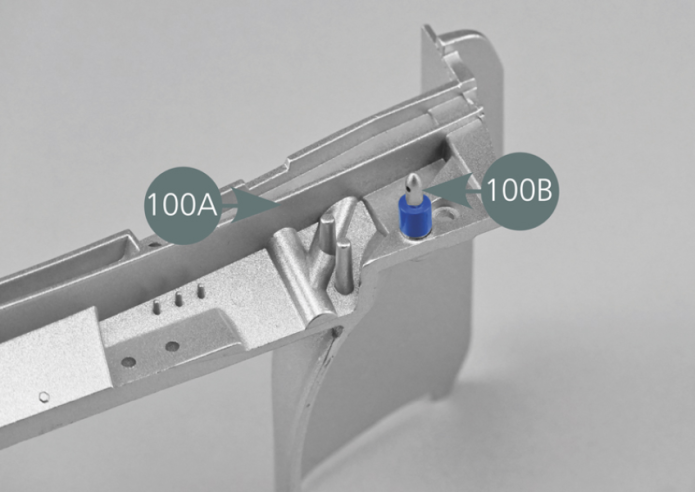

Place the second support (100B) into the opening located above the front compartment bulkhead (100A), then secure it from the rear with an AM screw.
Etape 3

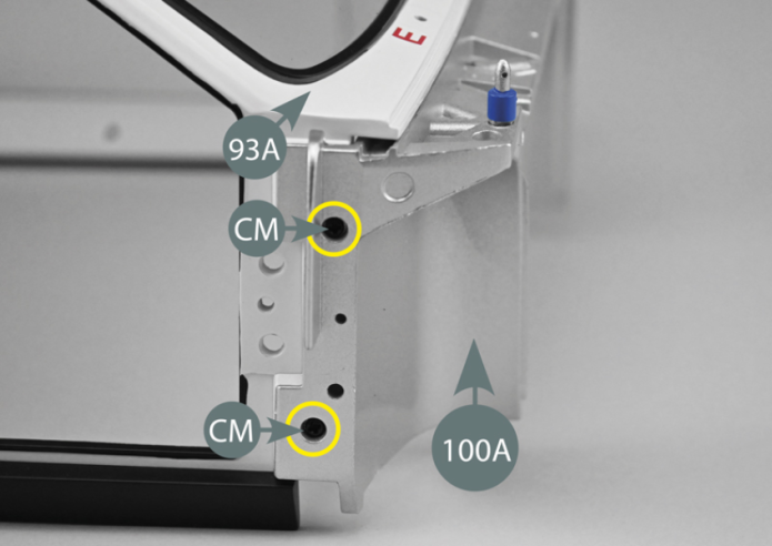
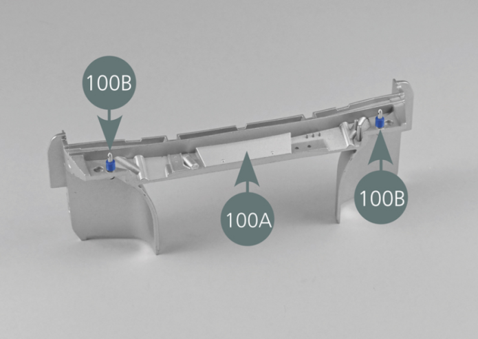
Positionner la cloison d’habitacle avant 100A à l’avant de la partie centrale de la carrosserie 93A.
Aligner les trous latéraux et fixer la cloison 100A sur la carrosserie 93A avec deux vis CM de chaque côté (cercles jaunes).
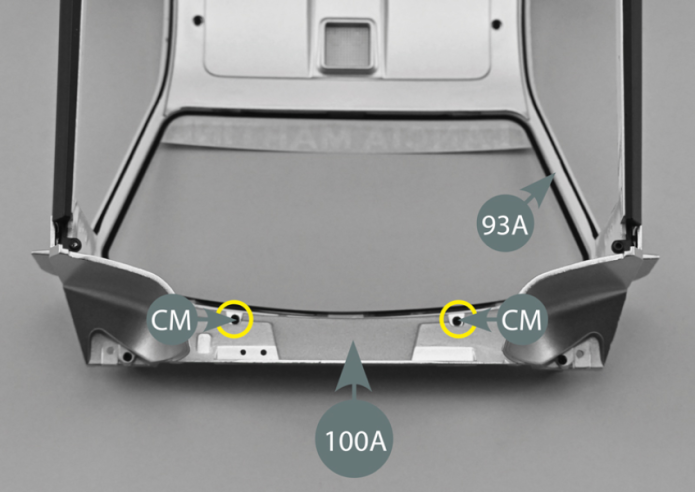
Retourner l’ensemble et fixer la cloison 100A sur la carrosserie 93A avec deux vis CM depuis l’intérieur.
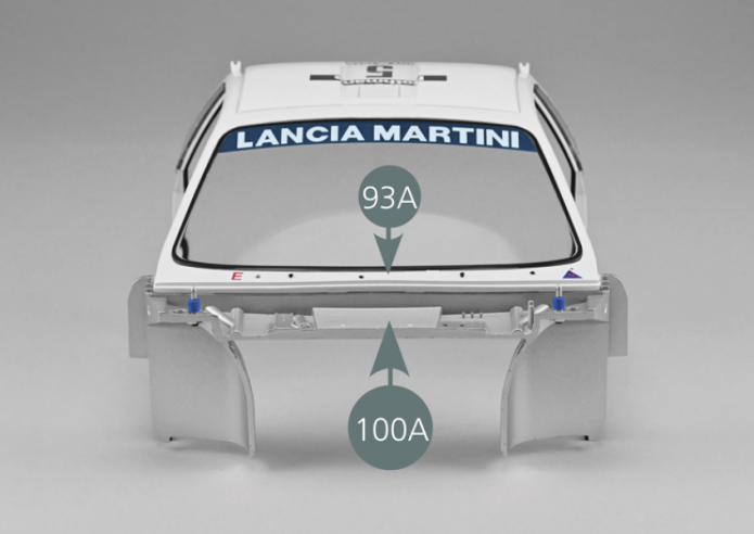
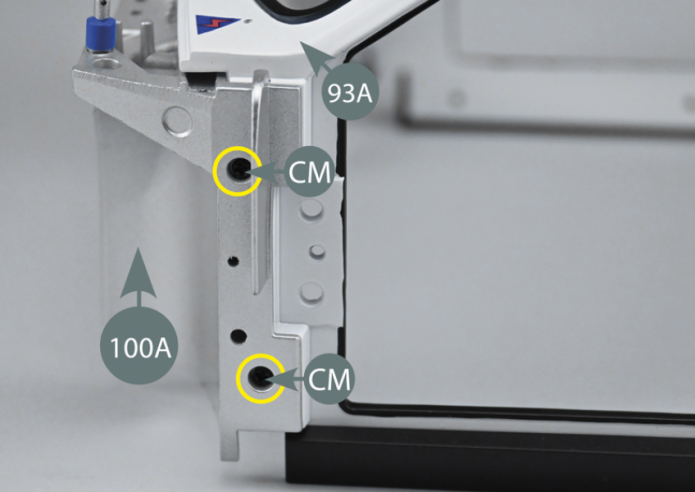
Position the front compartment bulkhead (100A) at the front of the central body (93A). Align the openings at the side and fix the bulkhead (100A) to the central body (93A) with two CM screws on each side (yellow circles). Turn the assembly over and secure – from the inside - the bulkhead (100A) to the body (93A) with two CM screws.

Vue générale