English
 français
 Deutsch
 español
 italiano
 português


Box 27
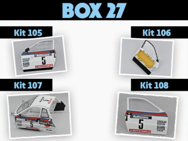
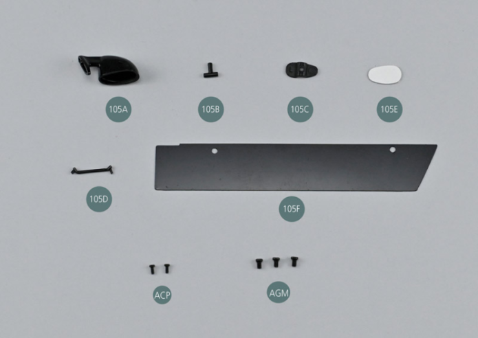
Parts of kit
- 105A Left exterior mirror
- 105B Mirror joint
- 105C Mirror support
- 105D Support rod
Etape 1
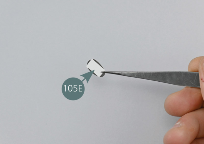
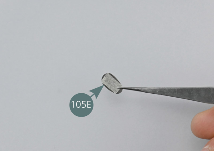
- 105E Rearview mirror
- 105F Door sill protection
- Screw ACP P 1.4 x 3 mm (x 2)
- Screw AGM M 2.0 x 3 mm (x 3)

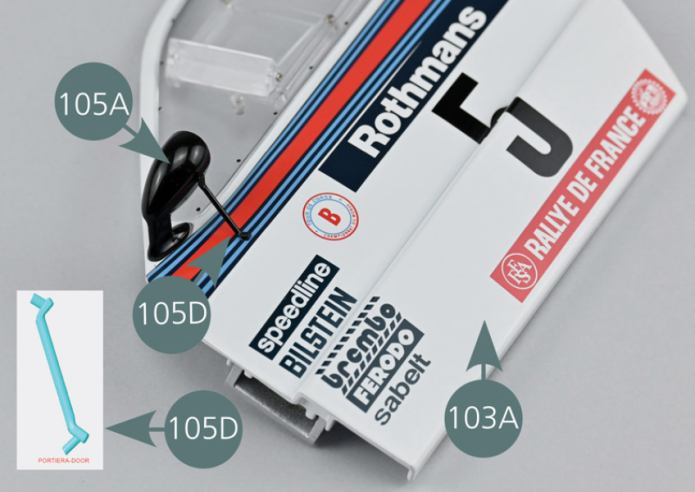
Placer le rétroviseur 105A, l’articulation 105B et le support 105C sur la surface de travail.
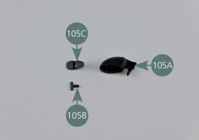
Place the mirror (105A), the joint (105B) and the support (105C) on the work surface.
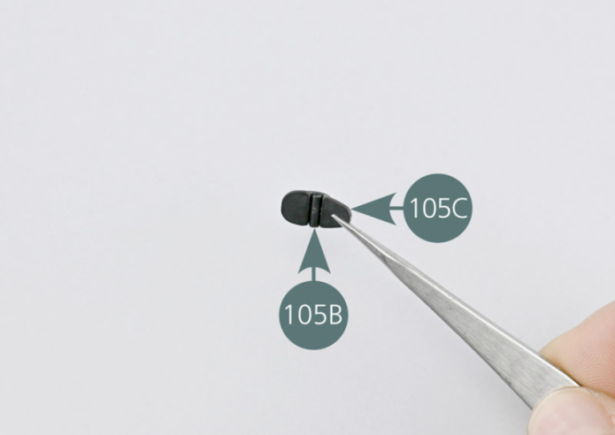

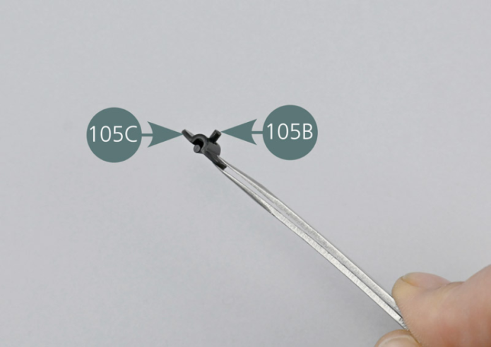
Etape 2
Insert the pin of the joint (105B) into the opening located at the base of the mirror support (105C), as shown in the photos.

Positionner l’assemblage réalisé dans le rétroviseur 105A.
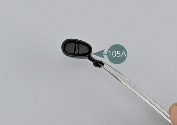
Position the assembly made in step 1 in the rearview mirror (105A).


Etape 3
Remove the protective film from the double-sided adhesive that is on the mirror (105E), then position the mirror (105E) on the support (105C) by pressing it and ensuring that the shapes match.
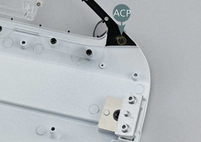
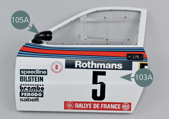
Positionner le rétroviseur extérieur gauche 105A sur la portière gauche 103A, puis le fixer depuis l’intérieur avec une vis ACP.

Etape 4
Place the left exterior mirror (105A) on the left door (103A), then secure it from the inside with an ACP screw.

Positionner la tige de soutien 105D en respectant le sens comme indiqué sur la photo de détail.
L’un des tétons s’insère dans le trou prévu sur la portière 103A et l’autre dans le trou situé à la base du rétroviseur 105A.

Etape 5
Position the support rod (105D) respecting the direction as indicated in the detail photo. One of the pins to be inserted into the opening provided on the door (103A) and the other into the opening located at the base of the rearview mirror (105A).
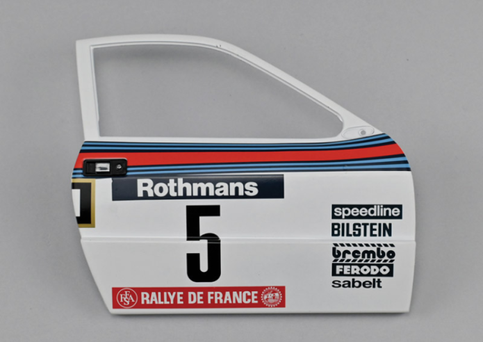
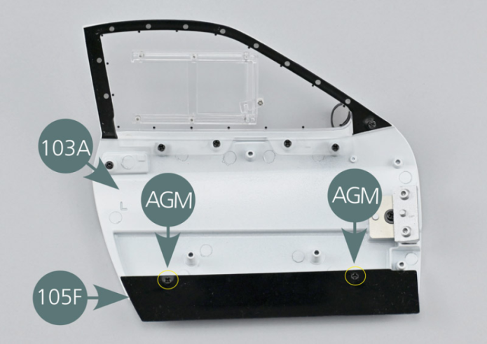
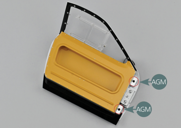
Positionner la protection 105F sur la base de la portière 103A, côté intérieur. Aligner les deux trous de la protection 105 F avec les deux supports de la portière 103E. Fixer la protection de bas de portière 105F avec deux vis AGM (cercles jaunes).
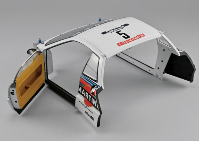
Vue générale
Position the sill protection (105F) on the base of the door (103A), interior side. Align the two openings of the sill protection (105F) with the two supports of the door (103E). Secure the door sill protection (105F) with two AGM screws (yellow circles).
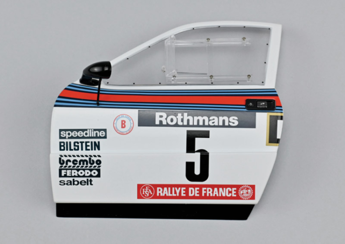
GENERAL VIEW
Parts of kit

Etape 1
- Screw AGM M 2.0 x 3 mm (x 4)
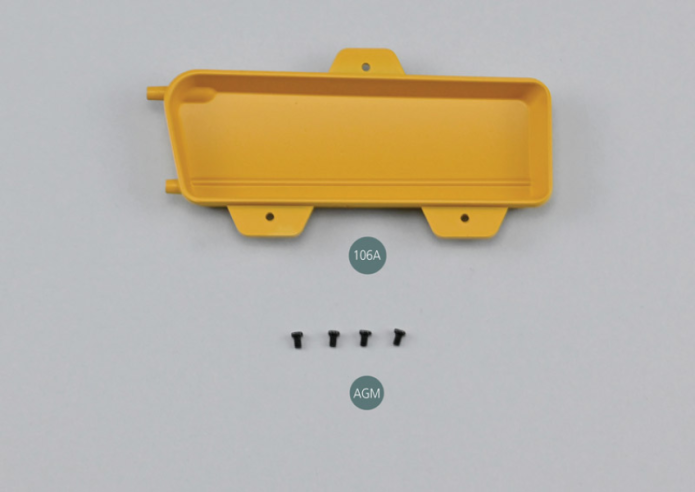
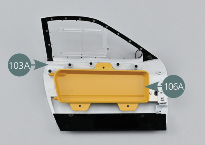
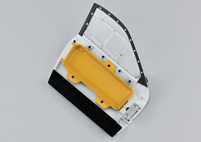
Positionner le panneau #A 106A sur l’intérieur de la portière gauche 103A comme indiqué, puis le fixer avec trois vis AGM.
Vue générale
Position panel #A (106A) on the inside of the left door (103A) as indicated, then secure it with three AGM screws.

GENERAL VIEW
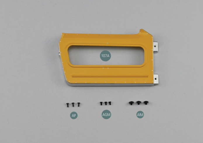
Parts of kit

Etape 1
- Screw AGM M 2.0 x 3 mm (x 3)
- Flat Head Screw AIM M 2.0 x 3 x 6 mm (x 3)
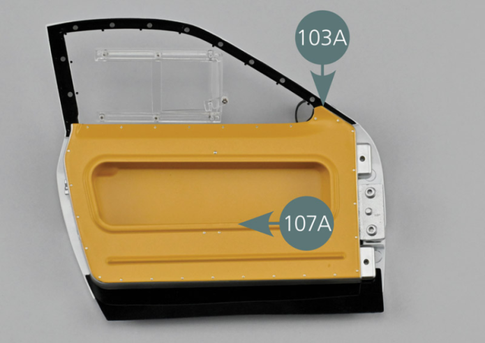
Positionner le panneau #B 107A sur l’intérieur de la portière gauche 103A comme indiqué, puis le fixer avec deux vis AGM dans les deux trous indiqués par un cercle rouge.

Position panel #B (107A) on the inside of the left door (103A) as shown, then secure it with two AIM screws in the two openings marked with a red circle.
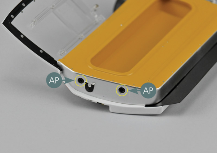
Fixer ensuite le panneau #B 107A sur le côté fermeture de la portière 103A avec deux vis AP (cercles jaunes).
Etape 2
Then secure panel #B (107A) on the closing side of the door (103A) with two AP screws (yellow circles).

Reprendre la carrosserie 93A assemblée lors des étapes précédentes.
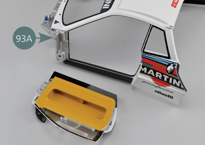
Take the bodywork (93A) assembled during the previous steps.
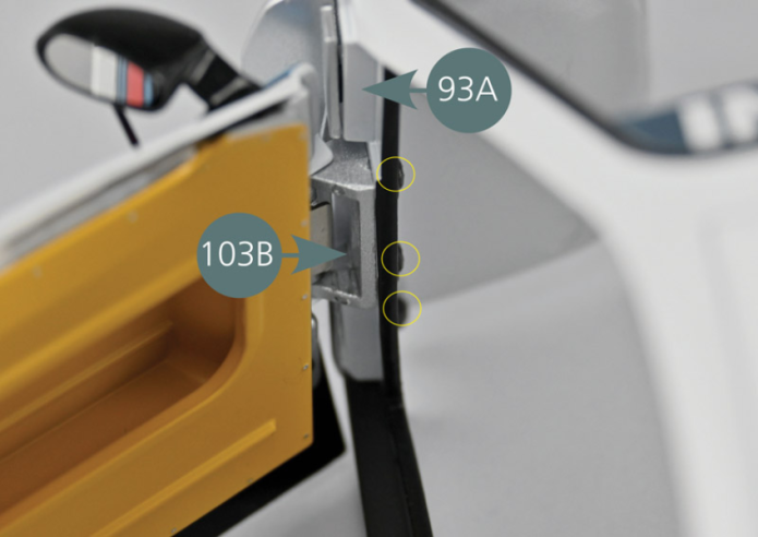
Open the door hinge (103B) and position the pins opposite the three openings in the bodywork (93A) as indicated (yellow circles).
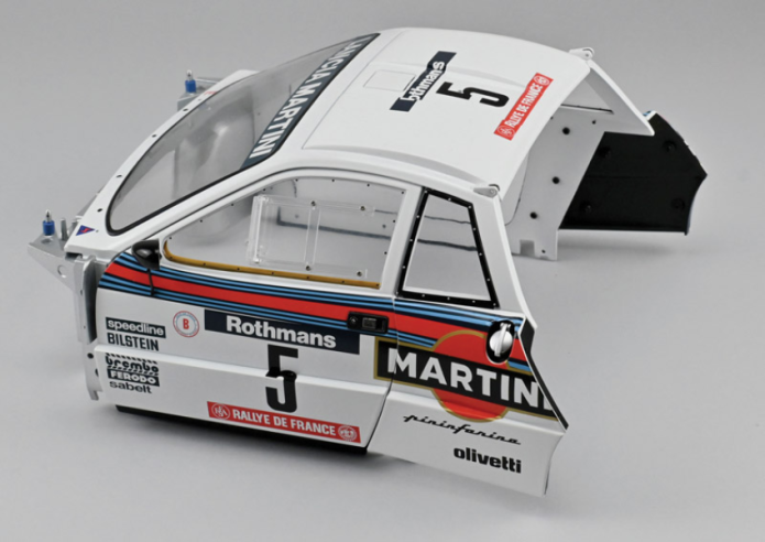
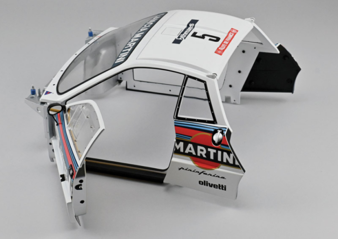
Vue générale
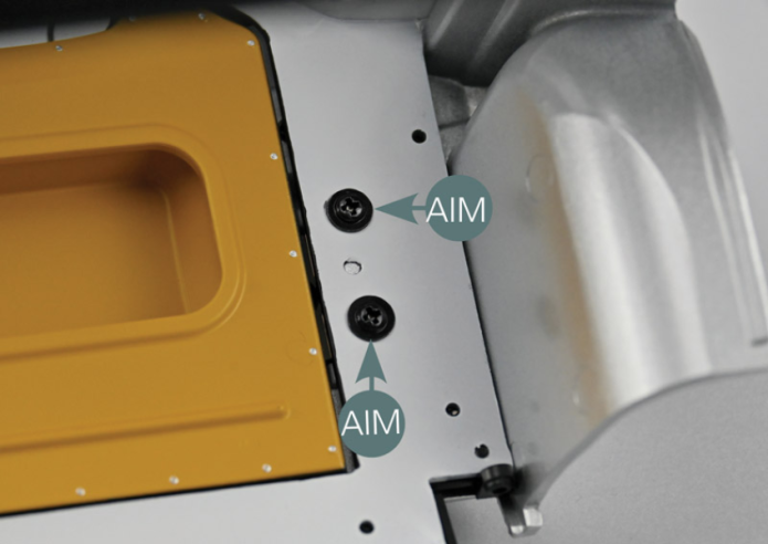
Close the door and secure it with two AIM screws. Start by lightly tightening the screws, then check alignment and then tighten the screws fully. Check the opening and closing of the door and act on the screws to adjust its positioning as best as possible if necessary.
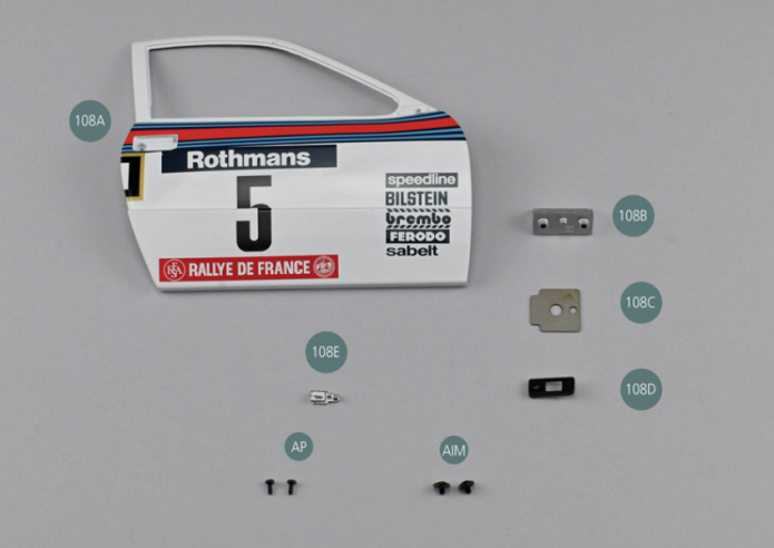
Kit 108 - Portière droite
Parts of kit

Etape 1
- 108E Door handle
- Screw AP M 1.7 x 4 mm (x 2)
- Flat head screw AIM M 2.0 x 3 x 6 mm (x 2)
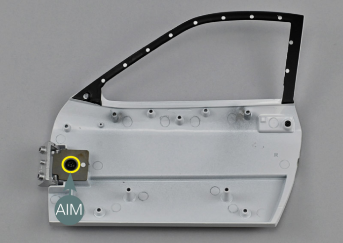
Placer le support de poignée de porte 108D face intérieure tournée vers le haut comme indiqué. Insérer la poignée de portière 108E dans le logement prévu en vérifiant que le téton est correctement aligné avec le trou (cercle jaune). La poignée de portière est assemblée à l’envers.

Place the door handle support (108D) with the inside facing up – see picture. Insert the door handle (108E) into the housing, ensuring that the pin is correctly aligned with the opening (yellow circle). The door handle is assembled upside down.
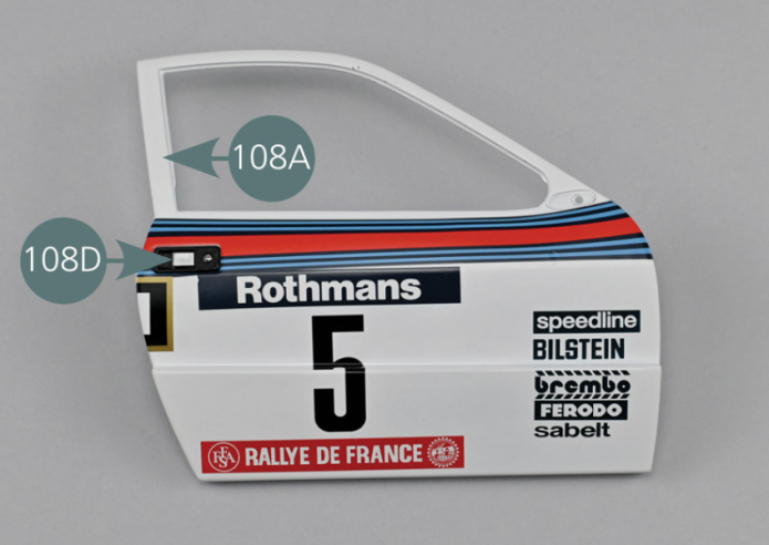
Position the door handle support (108D) on the right door (108A), matching the mounting opening as per picture.
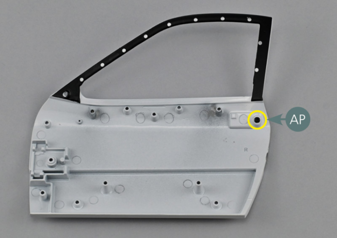
Etape 2
Secure the door handle support (108D) from the inside of the door with one AP screw.

Positionner la charnière de portière 108B sur la face intérieure de la portière 108A. Vérifier la bonne orientation de la charnière 108B.
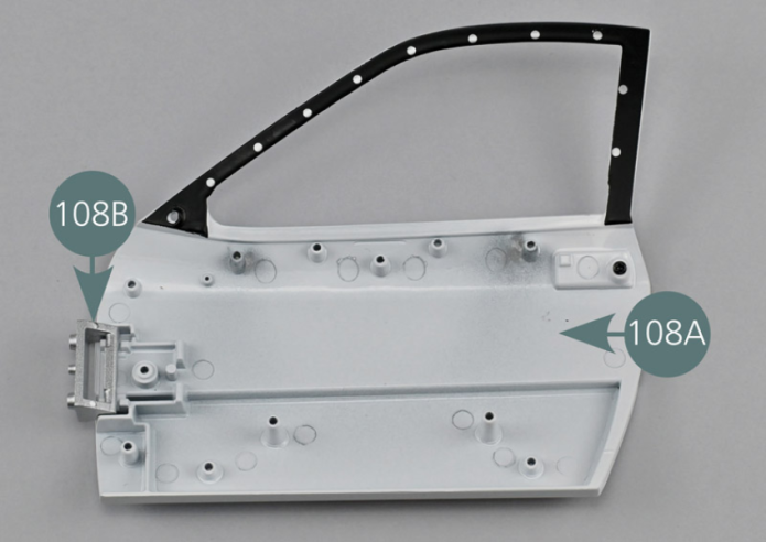
Position the door hinge (108B) on the inside of the door (103A). Check the correct orientation of the hinge (108B).

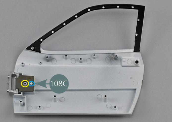
Position the hinge spring (108C) by centering the mounting opening with the seat of the screw (yellow circle) and aligning the rear pin with the rear opening of the spring (blue circle). Secure the hinge spring (108C) with an AIM screw.
Vérifier que le ressort de charnière 108C peut bouger et qu’il possède une résistance suffisante.
S’il est trop lâche, serrer la vis davantage.
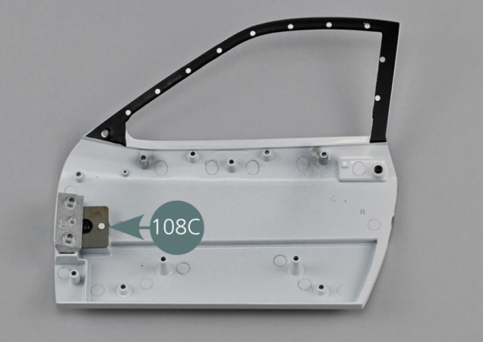
Vue générale
Check that the hinge spring (108C) can move and has sufficient strength. If it is too loose, tighten the screw further.