English
 français
 Deutsch
 español
 italiano
 português


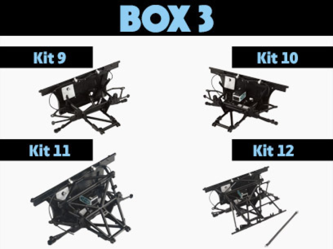
Box 3
Kit 9 - ASSEMBLING AND FITTING THE FIREWALL
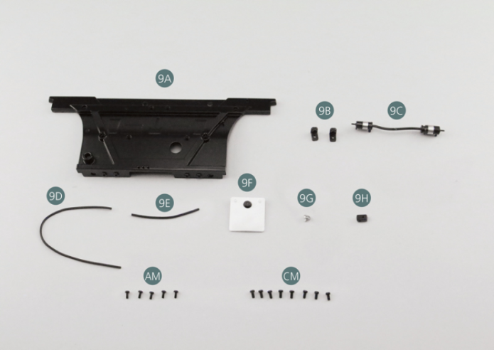
Parts of kit
- 9A Firewall
- 9B Bracket (x 2)
- 9C Oil filter and pump
- 9D Oil hose
- 9E Oil hose
- 9F Windshield washer fluid reservoir
- 9G Cap
- 9H Universal joint
- AM Screw M 1.7 x 4 mm (x 5)
- CM Screw M 2.0 x 4 mm (x 8)
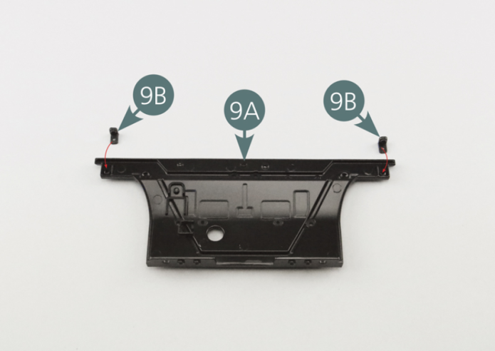
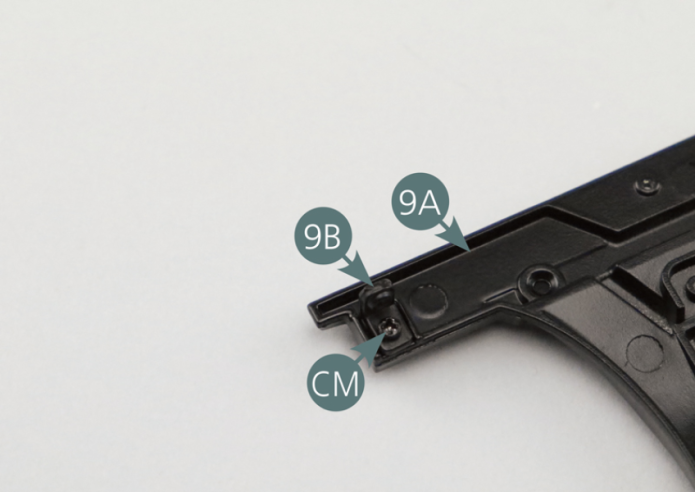
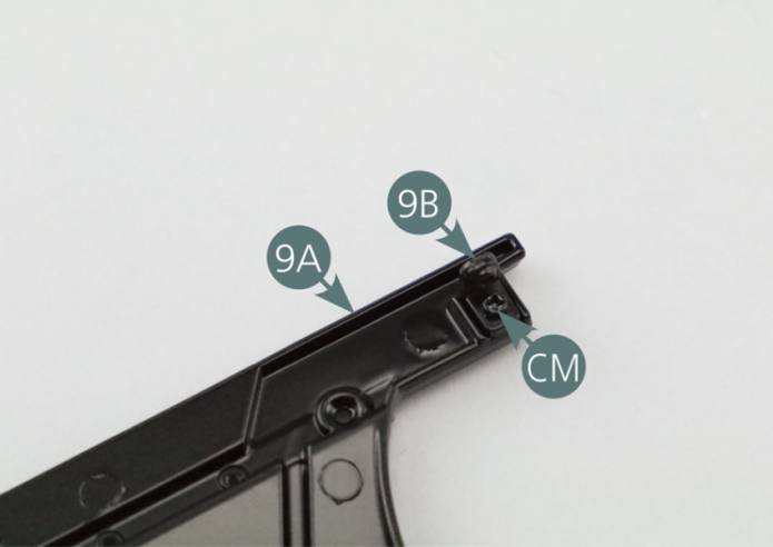
Step 1
Position the two brackets (9B) on the firewall (9A) and secure each one with a CM screw. The protruding part of the brackets must face upwards.
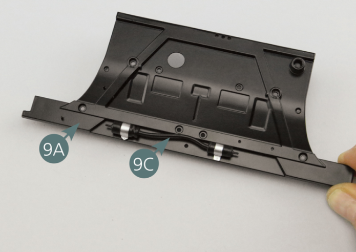
Step 2
Position the oil filter and pump (9C) on the firewall (9A) as shown on the picture.
Step 3
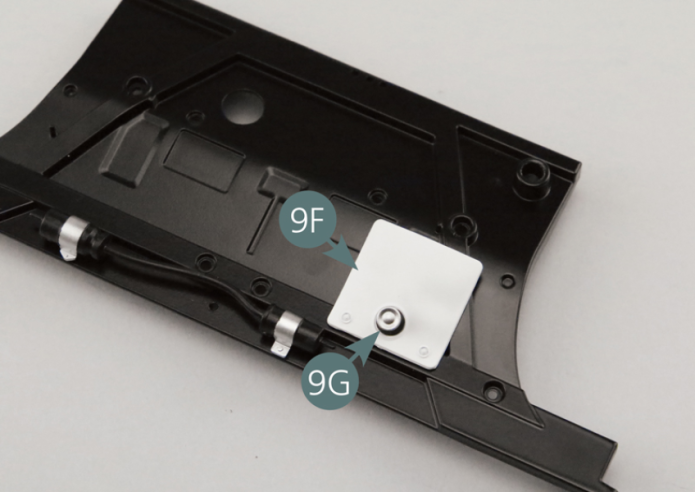
Position the windshield washer fluid reservoir (9F) – after having mounted the cap (9G) - on the firewall (9A).
Step 4
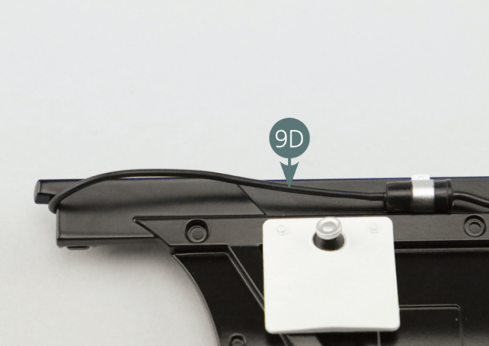
Connect the oil hose 12 cm (9D) and oil hose 4,5 cm (9E) to the oil filter and pump (9C). The long part must be placed on the same side as the windshield washer fluid reservoir (9F), the shortest part on the opposite side.
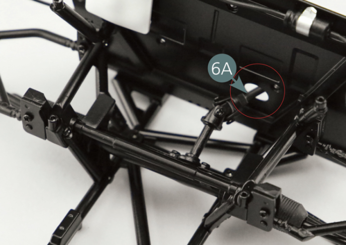
Step 5
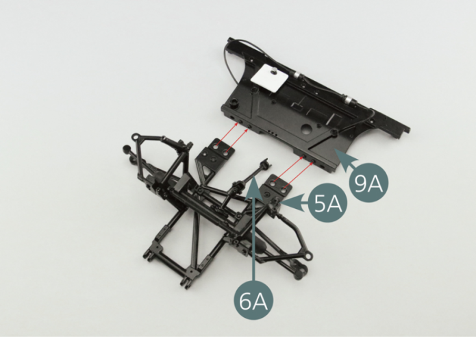
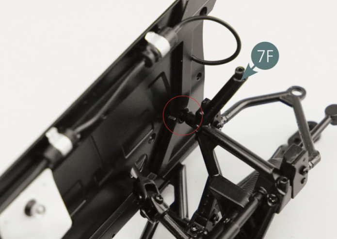
Position the firewall (9A) on the lower frame (5A) and the right (8F) and left (7F) side frames, passing the intermediate shaft (6A) through the opening in the firewall (9A).
Step 6
Attach the firewall (9A) to the right (8F) and left (7F) side frames using two AM screws.
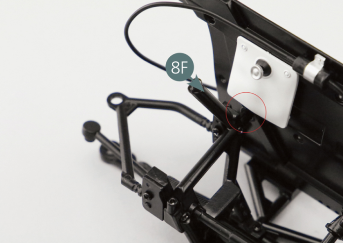

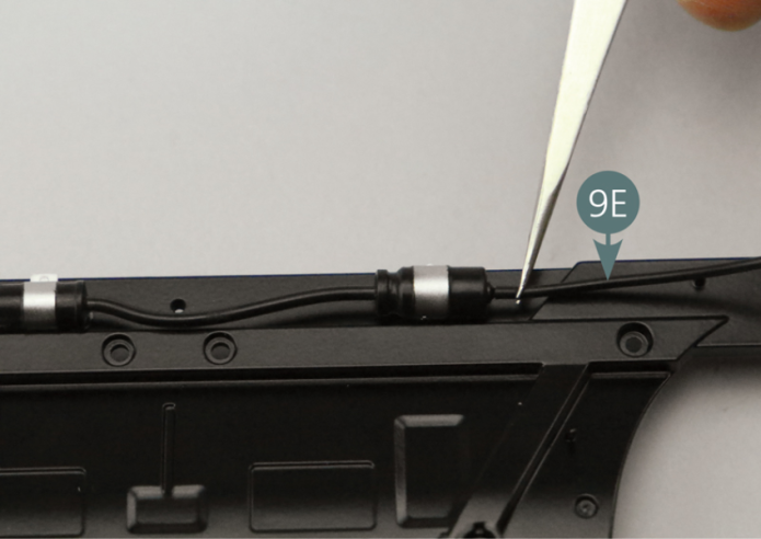
Connect the hose (9E) to the pin at the rear of the firewall (9A) - see illustration below.
Step 7
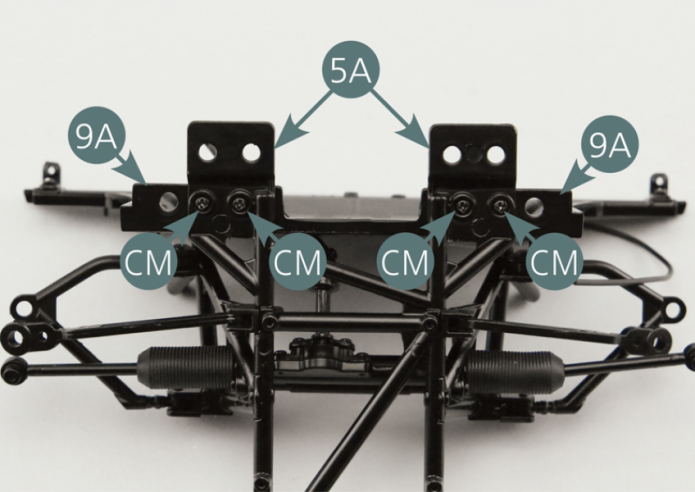
Fasten the firewall (9A) to the bottom frame (5A) using four CM screws.

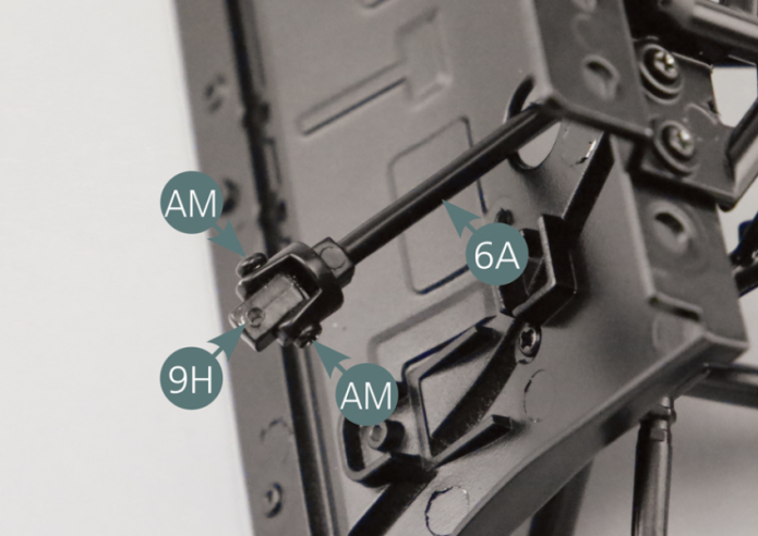
Step 8

Position the universal joint (9H) on the steering intermediate shaft (6A) and secure it with two AM screws.
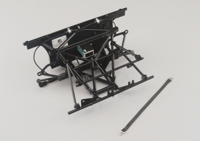
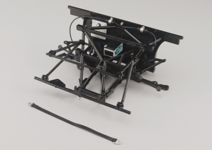
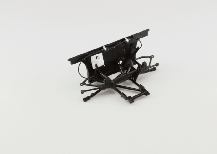
GENERAL VIEW

Kit 10 - ASSEMBLY AND INSTALLATION OF THE BATTERY
Parts of kit
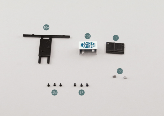
Step 1
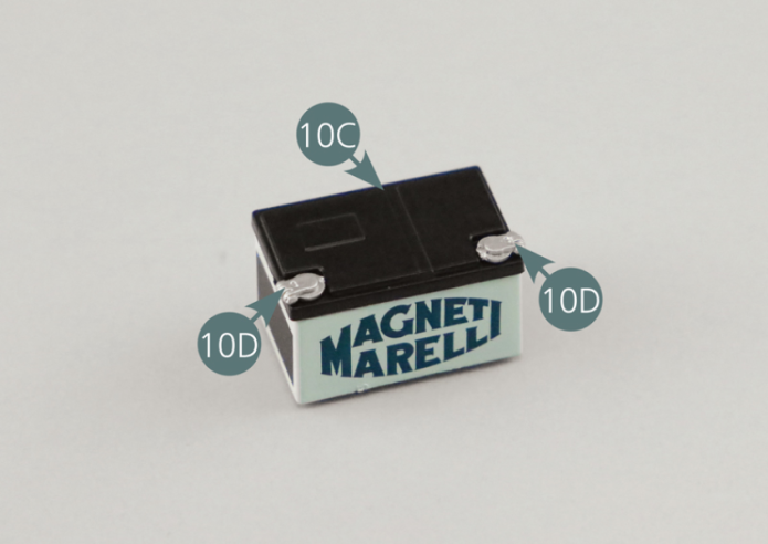
Place the battery cover (10C) on the battery (10B). Position the two battery terminals (10D) on the battery cover (10C).

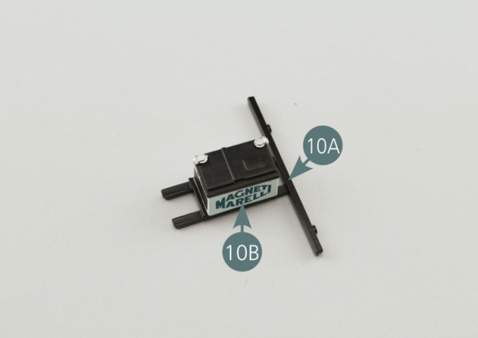
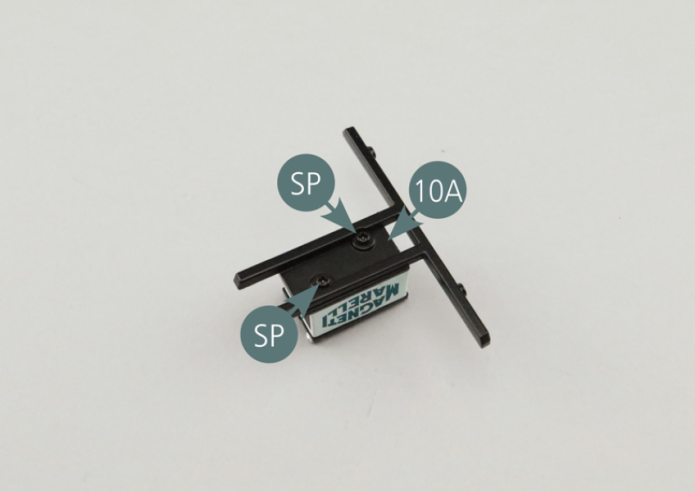
Step 2

Position the battery (10B) onto the battery carrier (10A) and secure it with two SP screws.
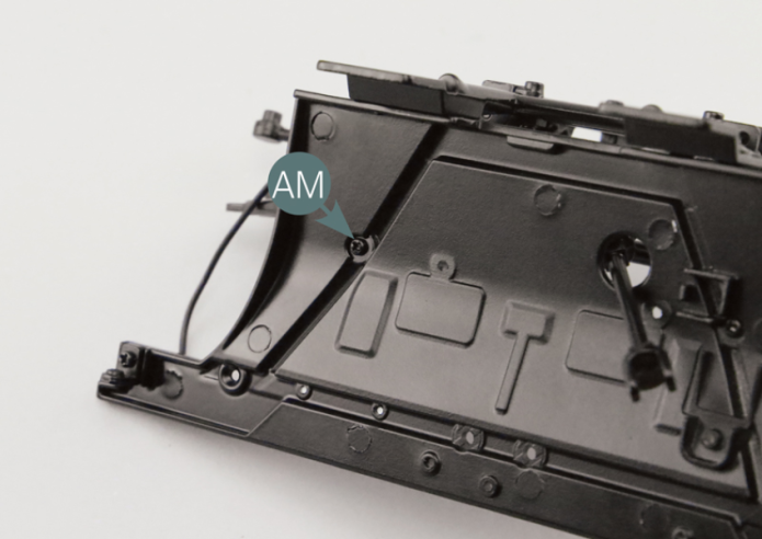
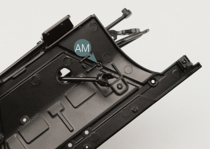
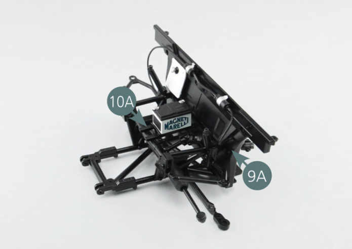
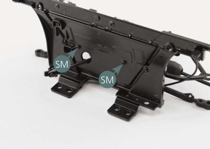
Step 3

Position the battery support (10A) on the firewall (9A) and fasten it from behind using two SM screws.
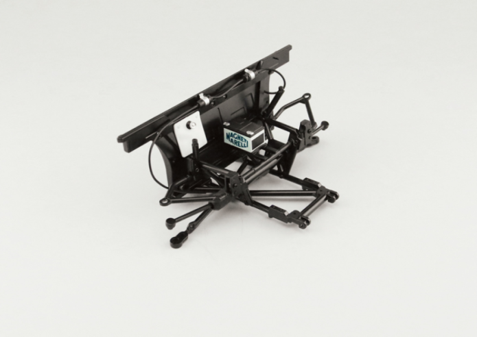
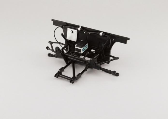
GENERAL VIEW

Kit 11- ASSEMBLY OF FRONT TUBULAR CAGE FRAME AND JACK ASSEMBLY
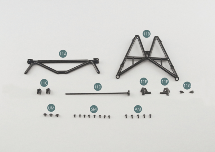
Parts of kit
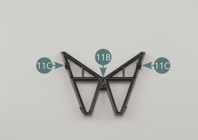
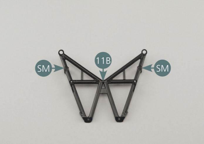
Step 1

Position the two brackets (11C) on the inclined chassis frame (11B). Secure with 2 SM screws.
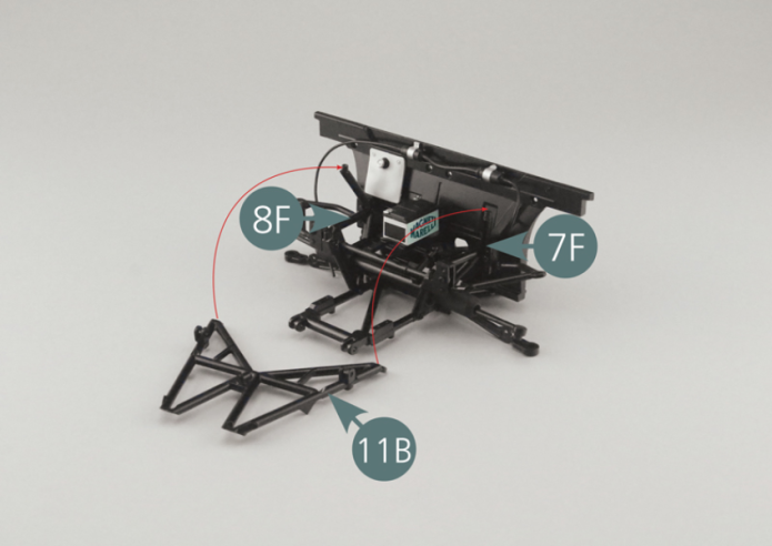
Etape 2
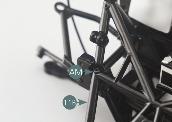
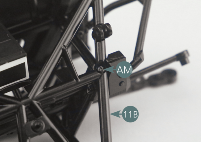
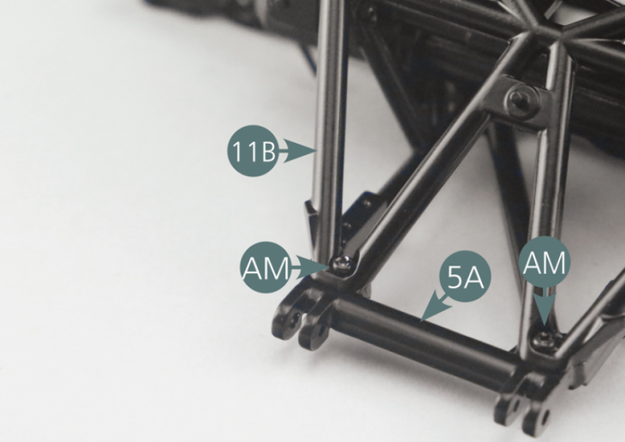
Position the inclined chassis frame (11B) on the lower frame (5A) and on the right (8F) and left (7F) side frames, then secure it with four AM screws.

Positionner le cadre de châssis incliné 11B sur le cadre de châssis inférieur 5A et sur les cadres de châssis latéraux droit 8F et gauche 7F, puis le fixer avec quatre vis AM.
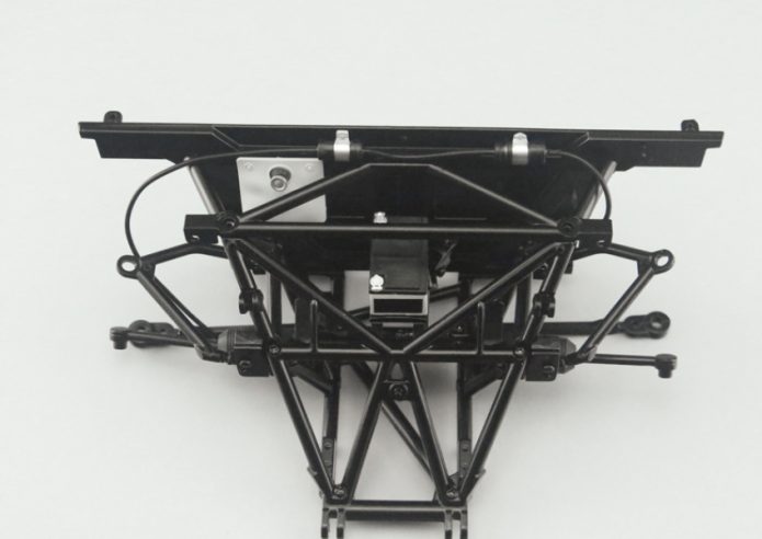
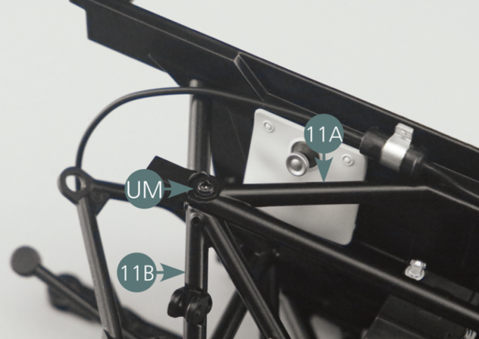
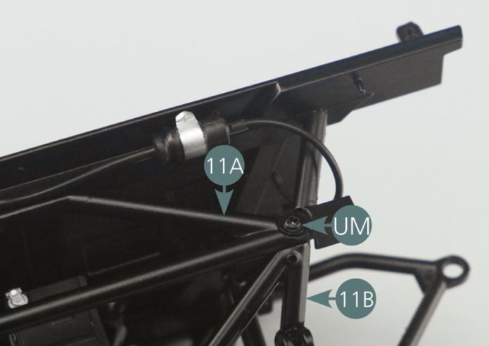
Etape 3
Position the top frame (11A) on the firewall (9A) and on the right (8F) and left (7F) side frames, then secure it with four SM screws and two UM screws respectively.
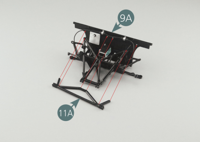
Positionner le cadre de châssis supérieur 11A sur la cloison pare-feu 9A et sur les cadres de châssis latéraux droit 8F et gauche 7F, puis le fixer respectivement avec quatre vis SM et deux vis UM.

Etape 4
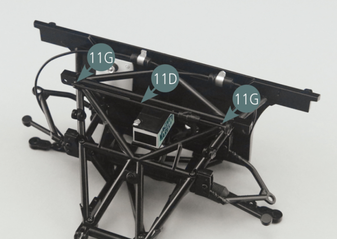
Position the two subframe supports (11G) on the top chassis frame (11B).

Positionner les deux supports en berceau 11G sur le cadre de châssis supérieur 11B.
Etape 5
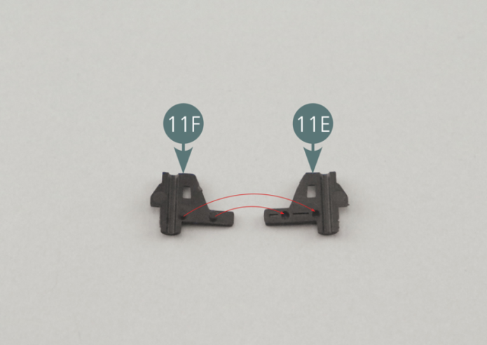
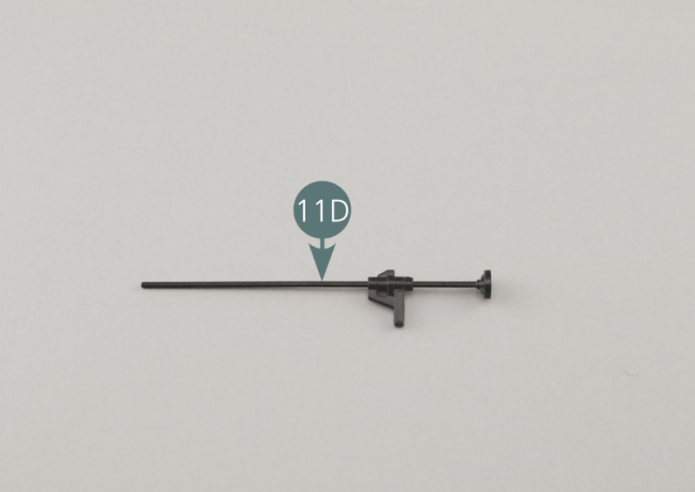
Position the male jack lever (11F) on the female jack lever (11E). Then insert the jack rod (11D) into the lever, as shown in the illustration.

Positionner le levier de cric 11F (mâle) sur le levier de cric 11E (femelle).
Insérer ensuite la barre de cric 11D dans le levier, comme indiqué sur l’illustration.
Etape 6
Click the jack bar assembly (11D) into the two cradle supports (11G).

Cliquer l’assemblage de la barre de cric 11D sur les deux supports en berceau 11G.
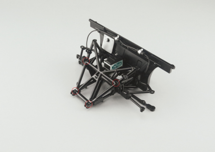
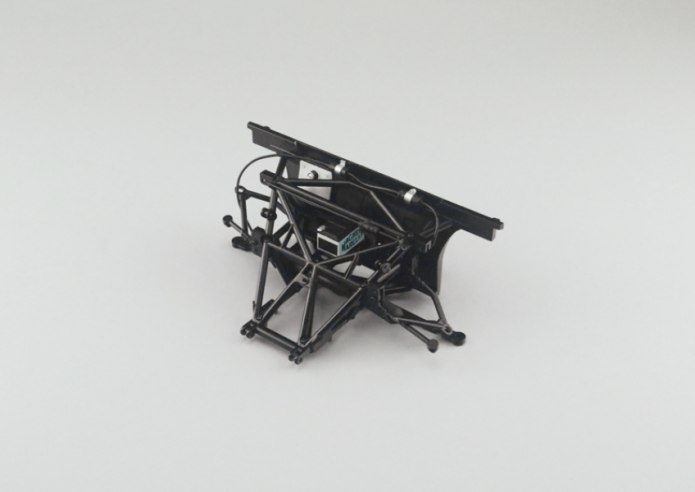
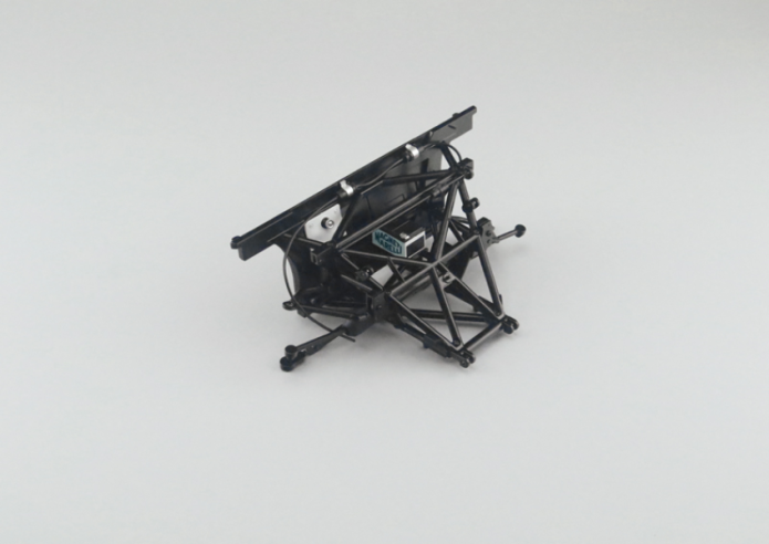
Vue générale

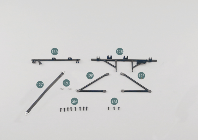
Kit 12 - Assemblage du châssis cage tubulaire avant
Parts of kit
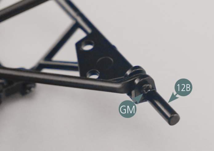
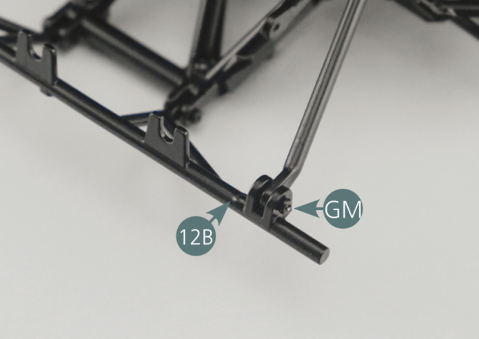
Etape 1
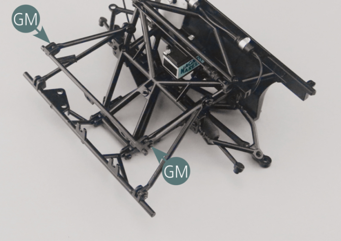
Position the lower bar (12B) on the lower frame (5A) and secure it with two GM screws.
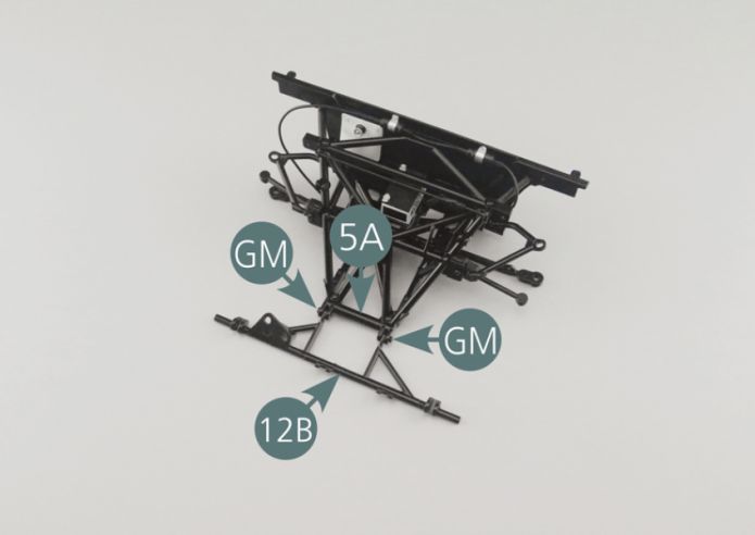
Positionner la barre inférieure 12B sur le cadre de châssis inférieur 5A et la fixer avec deux vis GM.

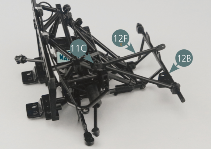
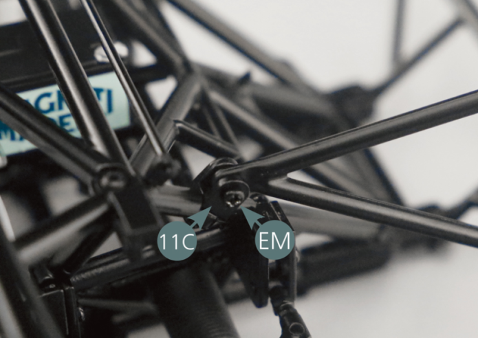
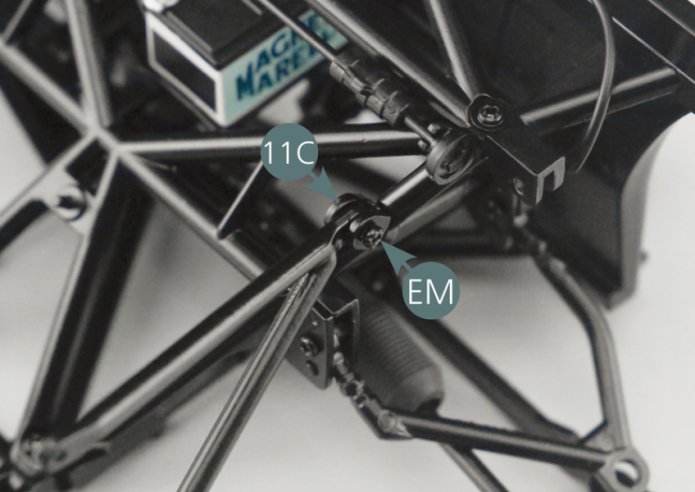
Etape 2
Position the right vertical tubular frame (12F) on the bracket (11C) and the lower bar (12B), then secure with an EM screw and a GM screw respectively.

Positionner le montant de cadre tubulaire droit 12F sur le support 11C et la barre inférieure 12B, puis le fixer respectivement avec une vis EM et une vis GM.
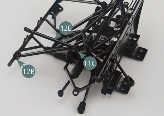
Etape 3
Position the left vertical tubular frame (12E) on the bracket (11C) and the lower bar (12B), then secure it with one EM screw and one GM screw respectively.

Positionner le montant de cadre tubulaire gauche 12E sur le support 11C et la barre inférieure 12B, puis le fixer respectivement avec une vis EM et une vis GM.
Etape 4
Position the upper bar (12A) on the right (12F) and left (12E) vertical tubular frame, then secure it with two GM screws.
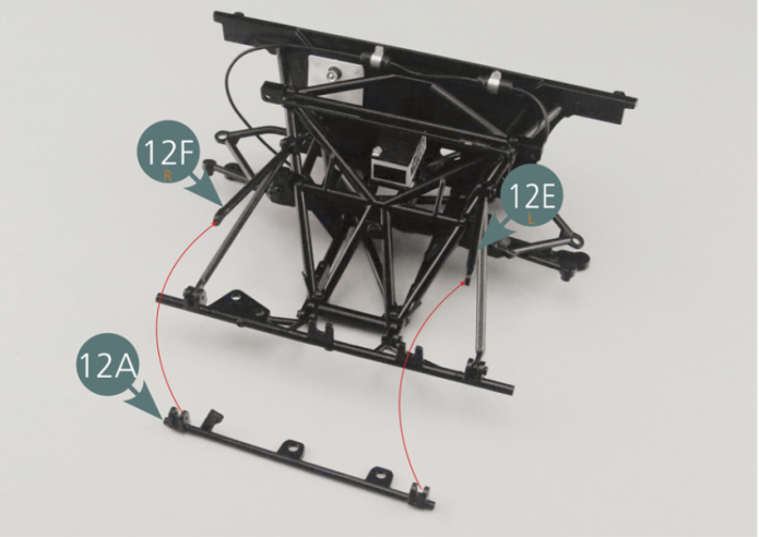
Positionner la barre supérieure 12A sur les montants de cadre tubulaire droit 12F et gauche 12E, puis la fixer avec deux vis GM.

Etape 5
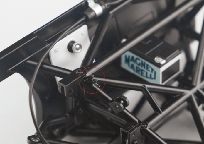
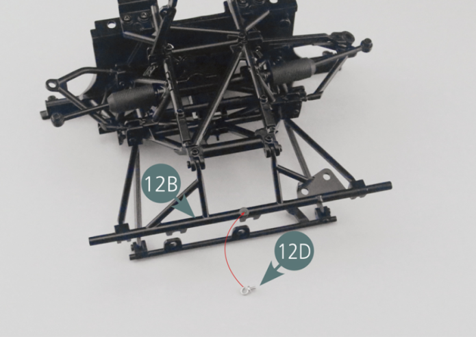
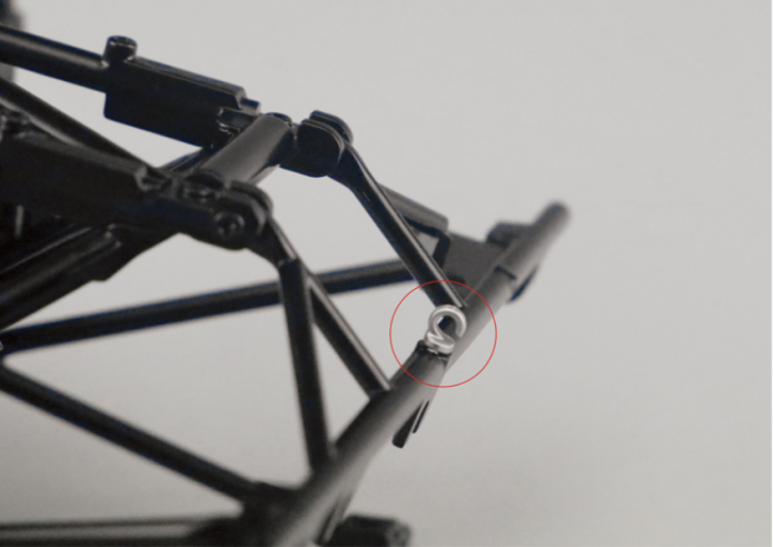
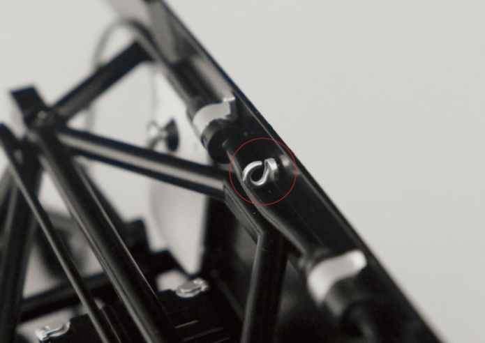
Place one of the hooks (12D) on the lower bar (12B), with the open end facing upwards (illustration below: red circle).

Positionner un crochet 12D sur la barre inférieure 12B, avec la partie ouverte vers le haut (illustration ci-dessous : cercle rouge).
Etape 6
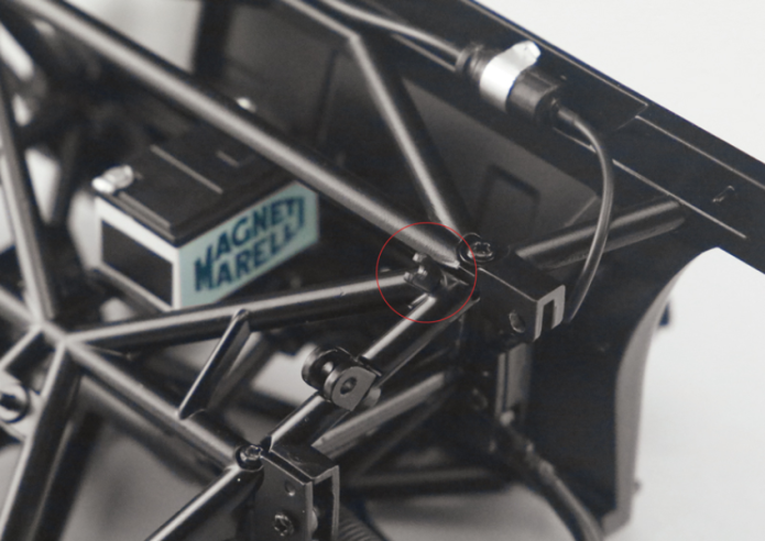
Place one of the hooks (12D) into the firewall (9A), with the open end facing upwards (illustration below: red circle).
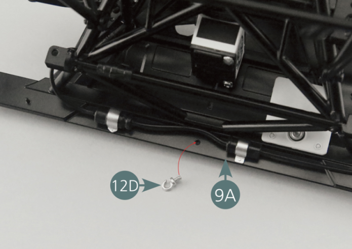
Positionner un crochet 12D sur la cloison pare-feu 9A, avec la partie ouverte vers le haut (illustration ci-dessous : cercle rouge).

Vue générale