English
 français
 Deutsch
 español
 italiano
 português


Box 5
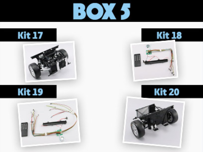
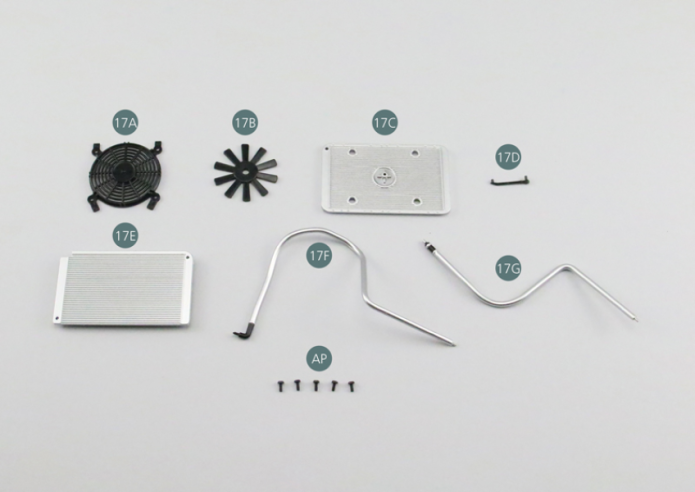
Kit 17 - MOUNTING OF THE RADIATOR AND FAN
Parts of kit
- 17A Fan grille
- 17B Fan propeller
- 17C Radiator (front part)
- 17D Overflow pipe
- 17E
- 17E Radiator (rear part)
- 17F Pipe A
- 17G Pipe B
- Screw AP P 1.7 x 4 mm (x 5)
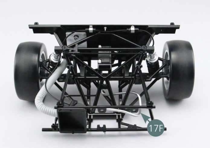
Step 1
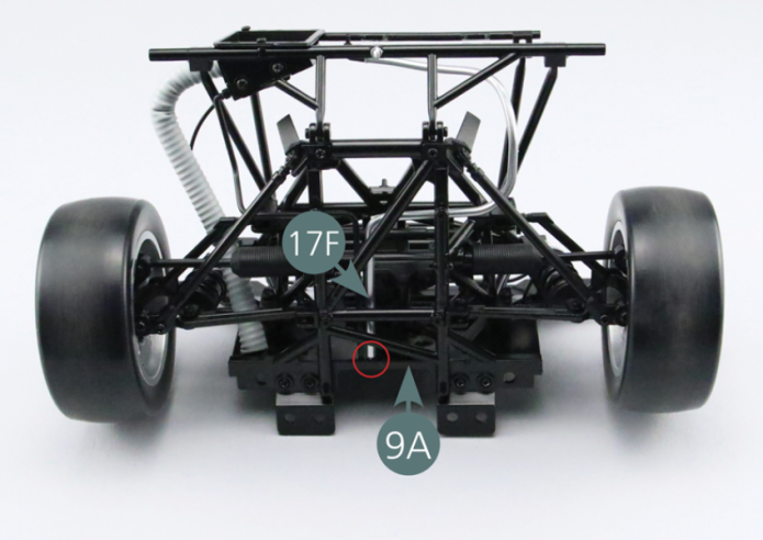
Place pipe A (17F) as shown in the illustration. Insert rear end of the pipe (17F) into the firewall (9A) - next to oil pipe (16D).
Step 2
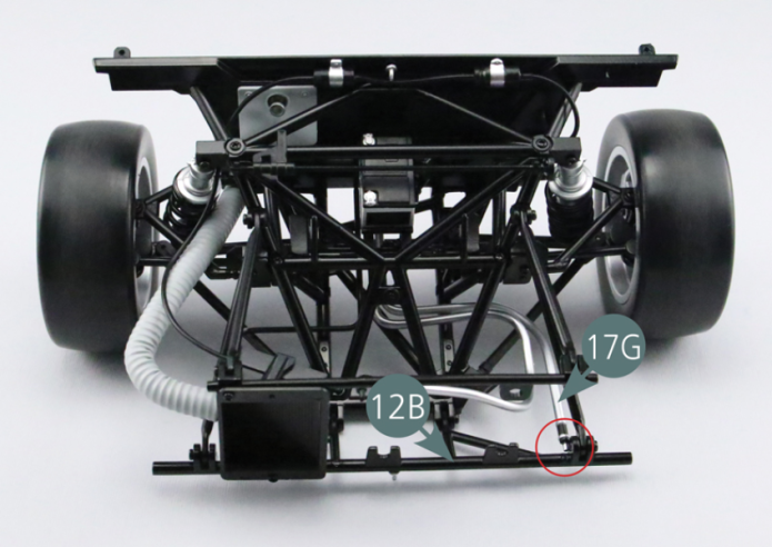
Position pipe B (17G) as shown in the illustration. Insert rear end of the pipe (17G) into the firewall (9A) - next to pipe (17F).

Step 3
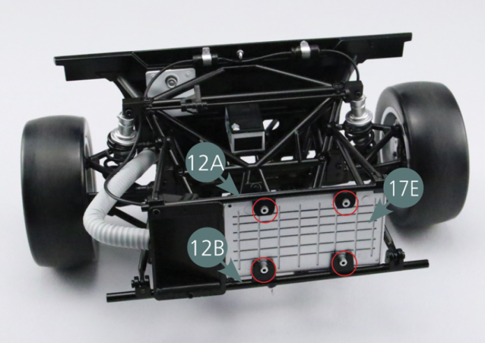
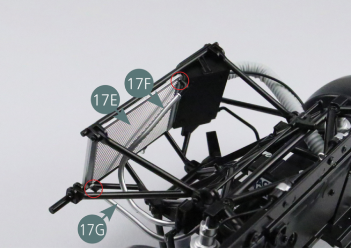
Position the rear part of the radiator (17E) between the upper (12A) and lower (12B) bar. Connect the front end of the pipes A (17F) and B (17G) to the rear part of the radiator (17E) as shown in the illustration.
Step 4
Position the front part of the radiator (17C) on the rear part of the radiator (17E).

Step 5
Place the fan propellor (17B) on the axis located in the center of the radiator (17C).
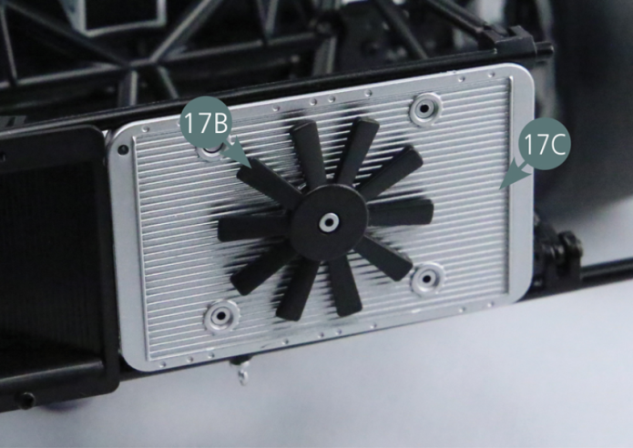
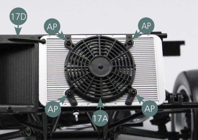
Step 6
Position the fan grille (17A) on the radiator (17C) and secure with four AP screws. Position the overflow pipe (17D) at the top left of the radiator (17C) - as shown in the illustration.
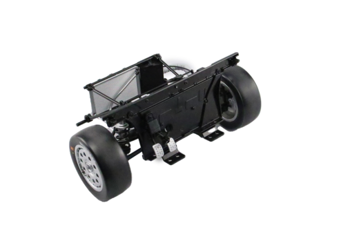
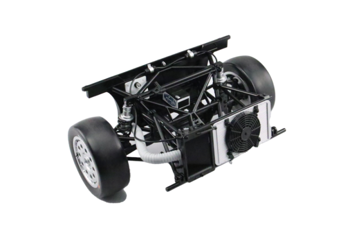
GENERAL VIEW
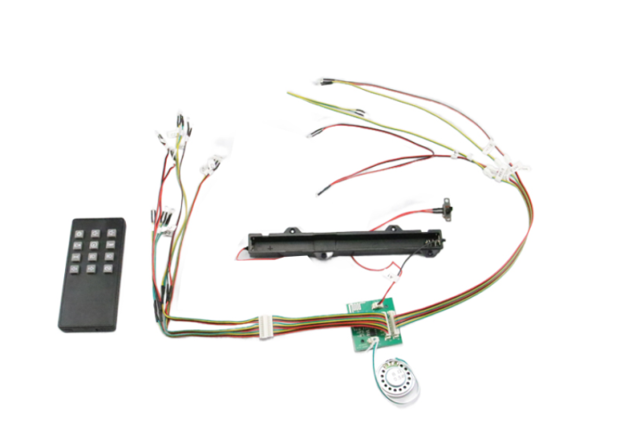
Kit 18 - MOUNTING OF THE SPEAKER AND REMOTE CONTROL
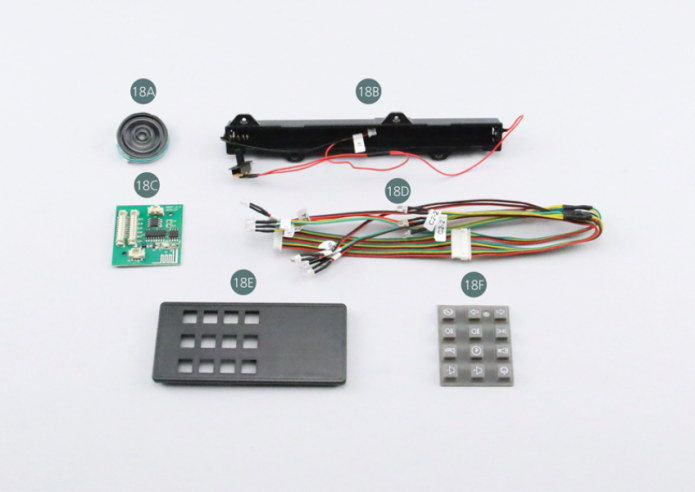
Parts of kit
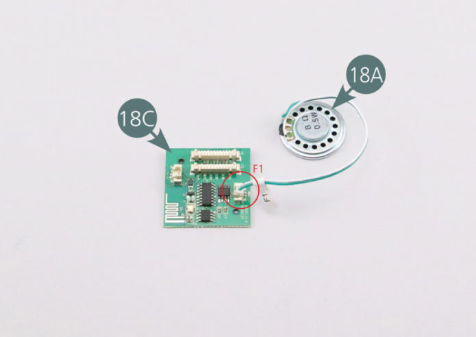
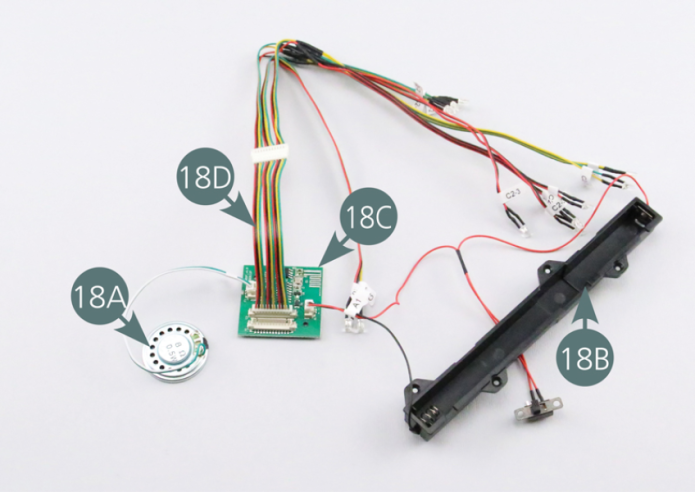
- 18A Speaker
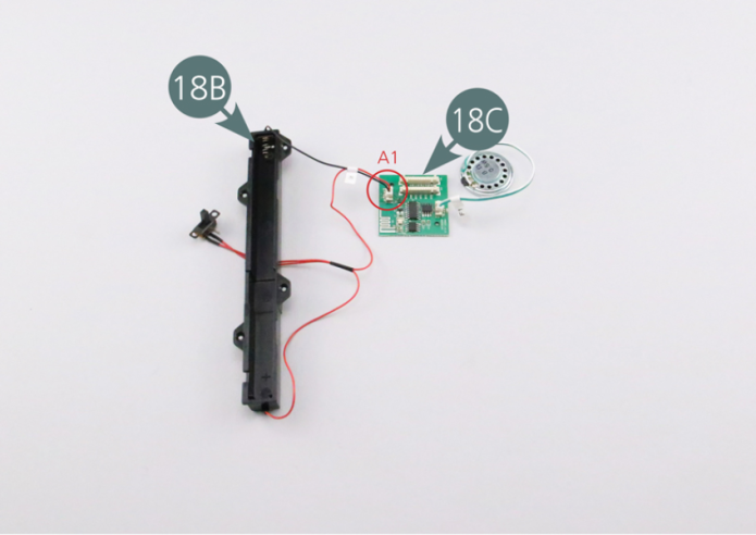
- 18B Battery Compartment
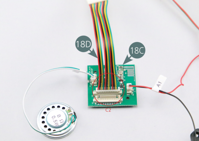
- 18C PCB
- 18D Headlight cables
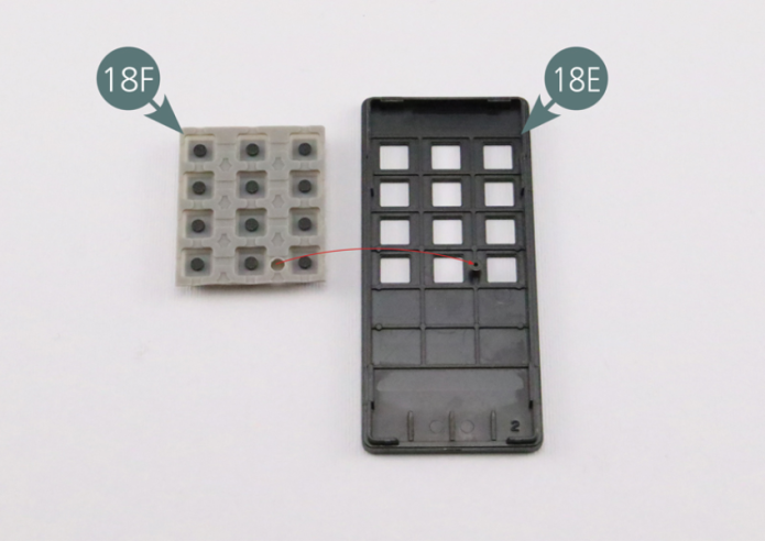
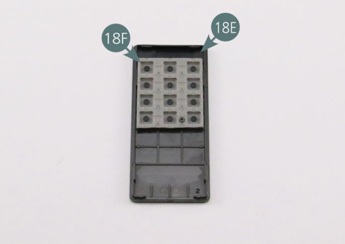
- 18E Remote control front plate
- 18F Remote control buttons
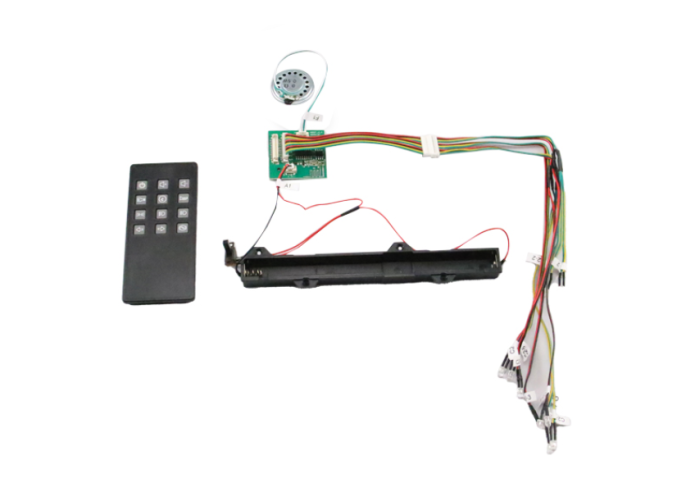
Step 1
Connect the speaker cable (18A) to the PCB (18C) - socket F1. Connect the cable from the battery compartment (18B) to the PCB (18C) - socket A1. Connect the headlight cable plug (18D) to the PCB (18C) - socket C2.
Step 2
Place the buttons of the remote (18F) into the front plate (18E) as shown in the illustrations.
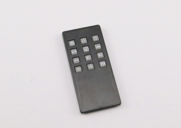
GENERAL VIEW
Kit 19 - MOUNTING OF THE REMOTE CONTROL AND WIRING
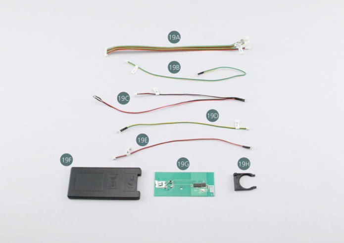
Parts of kit
- 19A Wire bundle tail light
- 19B Cable H1-1 Lighting License plate
- 19C Cable H1-2 Tail light
- 19D Cable H1-3 Left Blinking light
- 19E Cable H1-4 Right Blinking light
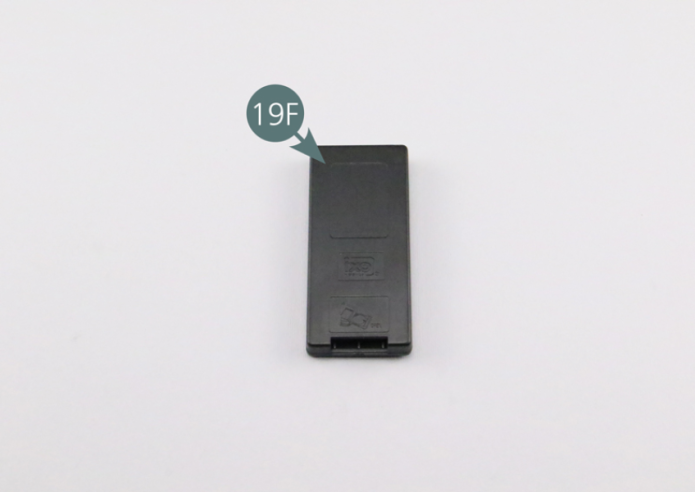
- 19F Remote control back plate
- 19G PCB remote control
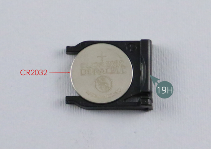
- 19H Battery holder
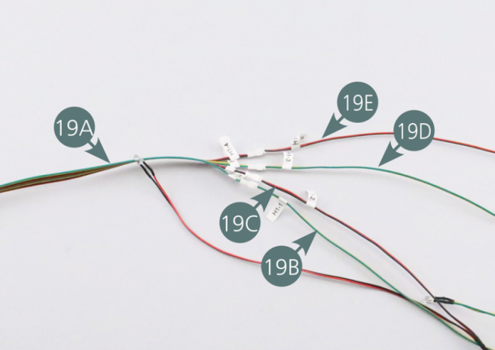
Step 1
Connect the cable of the license plate light (19B / H1-1), cable tail light (19C / H1-2), as well as the left (19D / H1-3) and right (19E / H1-4) cables of the blinking lights onto the wire bundle of the tail light (19A).
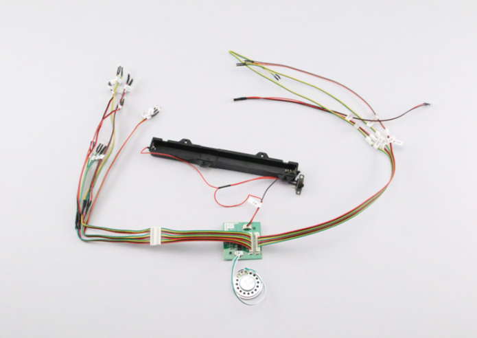
Step 2
Connect the wire bundle tail light (19A) to socket H1 on the PCB (18C).

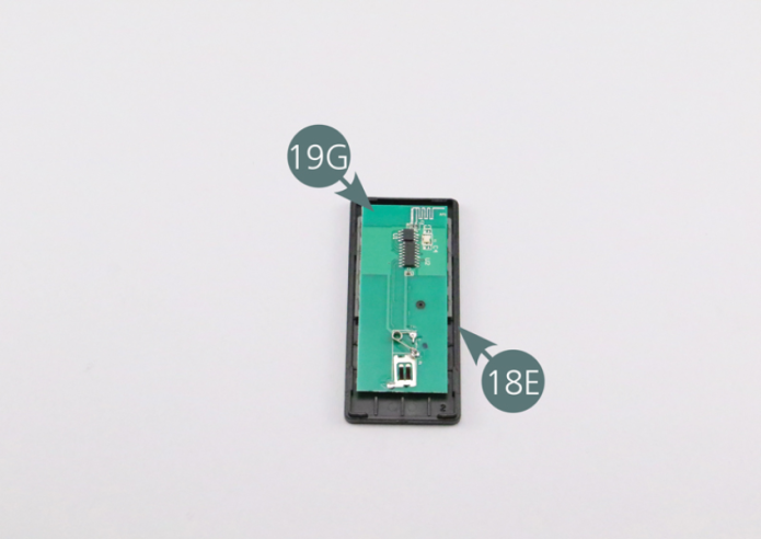
Step 3
Position the PCB remote (19G) into the front plate (18E). Close the remote control by placing the back plate (19F) onto it.
Step 4
Insert a CR2032 type battery into the holder (19H) - battery not supplied. Insert the battery holder (19H) into the remote control (19F).

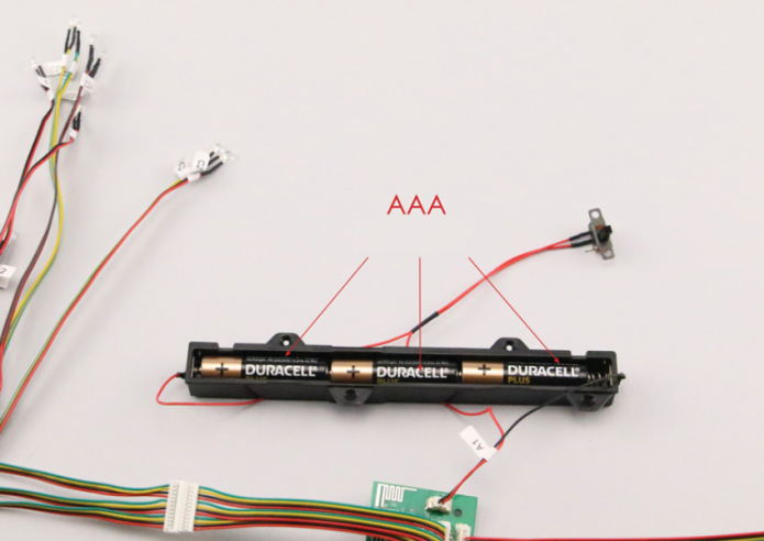
Step 5
Place three AAA batteries in the battery compartment (18B) - batteries not included. Set the switch to the "ON" position.

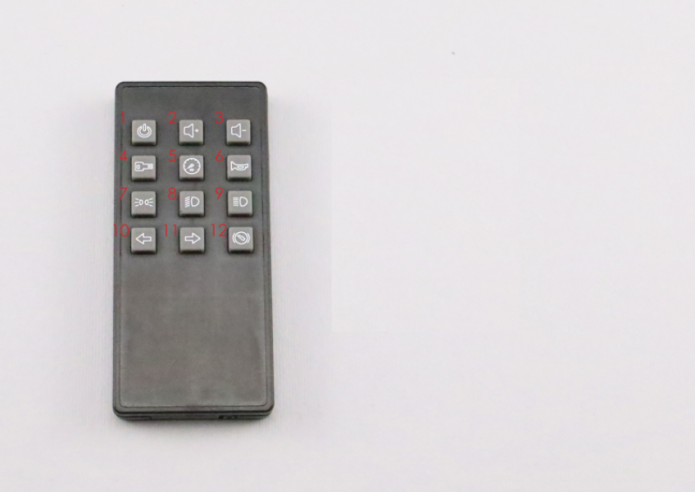
Step 6
The remote control allows you to test the different functions by pressing the buttons. The exact functions you can find in the illustration.
GENERAL VIEW
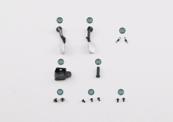
Kit 20 - MOUNTING OF THE BRAKE AND CLUTCH PEDALS
Parts of kit
- 20A Brake pedal
- 20B Clutch pedal
- 20C Spring (x 2)
- 20D Crankset
- 20E Crank axle
- Screw RP P 1.7 x 3 mm (x 2)
- Screw SP P 1.7 x 3 mm (x 3)
- Screw SM M 1.7 x 3 mm (x 2)
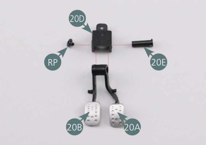
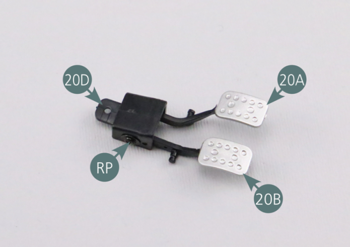
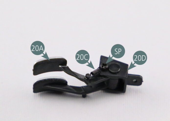
Step 1
Assemble the brake (20A) and clutch (20B) pedals, then position them both onto the pedal/crankset (20D). Pass the axle (20E) through the crankset and the two pedals (20A&20B) and secure with an RP screw.
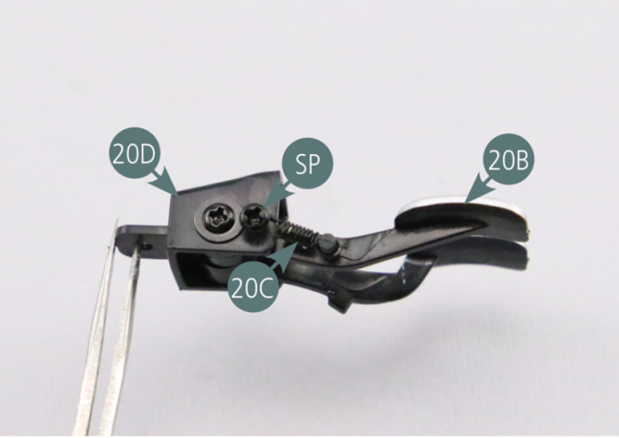
Step 2
Place one SP screw on the right side of the crankset (20D), then position one spring (20C) as indicated in the illustration. Place another SP screw on the left side of the crankset (20D), then position the second spring (20C) as shown.
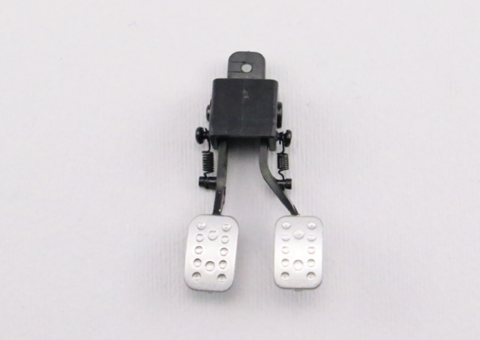
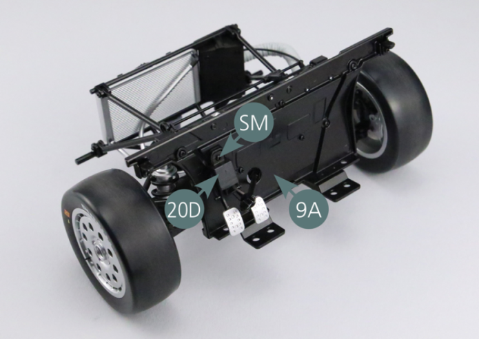
Step 3
Place the crankset (20D) on the firewall (9A) and secure with an SM screw.
GENERAL VIEW