English
 français
 Deutsch
 español
 italiano
 português


Box 6
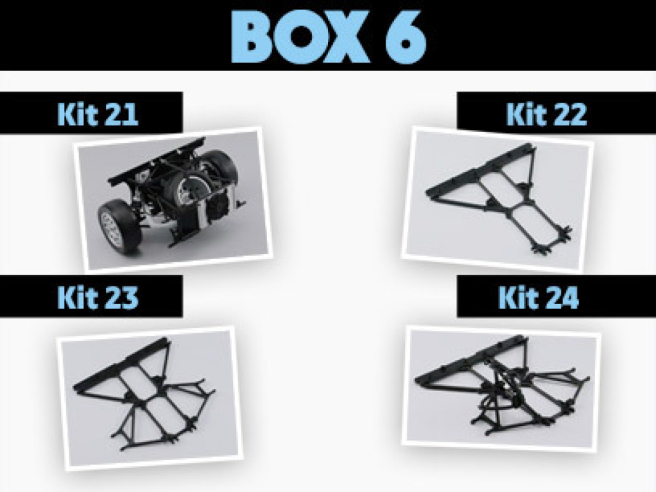
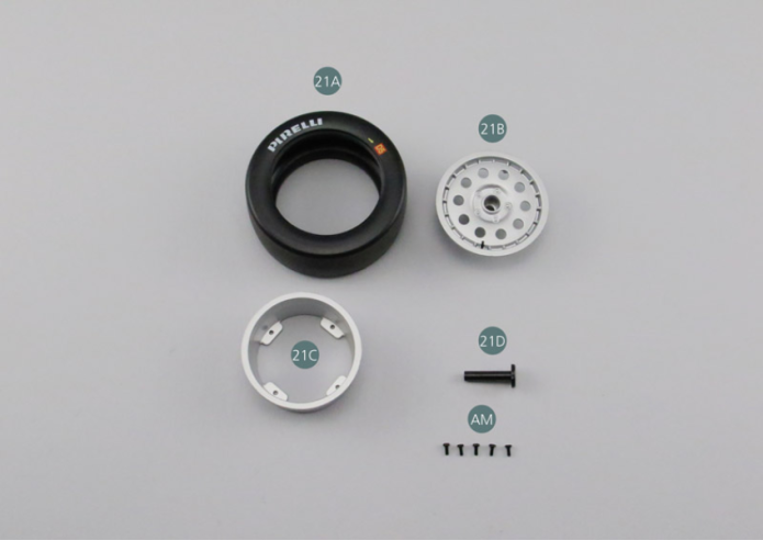
Kit 21 - MOUNTING OF THE SPARE WHEEL
Parts of kit
- 21A Tyre
- 21B Outer wheel rim
- 21C Inner wheel rim
- 21D Spare wheel carrier
- Screw AM M 1.7 x 4 mm (x 5)
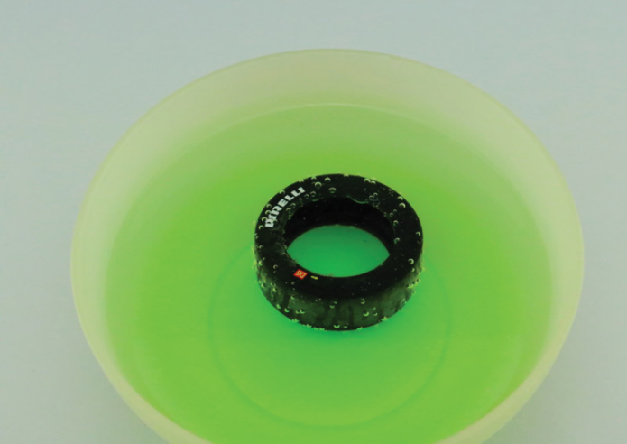
Step 1
Immerse the tyre (21A) into warm water for approx. 30 seconds to soften it. Once out of the water, dry it carefully, especially the inner part.
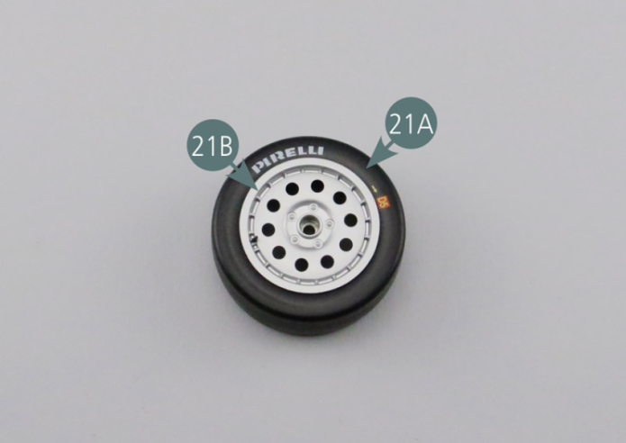
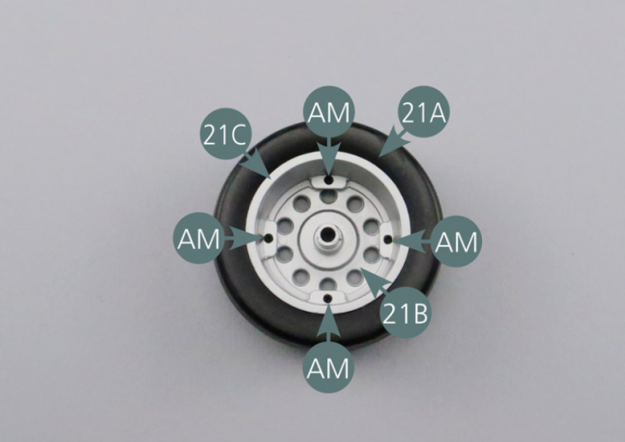
Step 2
Position the outer wheel rim (21B) into the tyre (21A) - on the side with the markings. Position the inner wheel rim (21C) in the tyre (21A) aligning it with the mounting holes of the outer rim (21B), then secure with four AM screws.
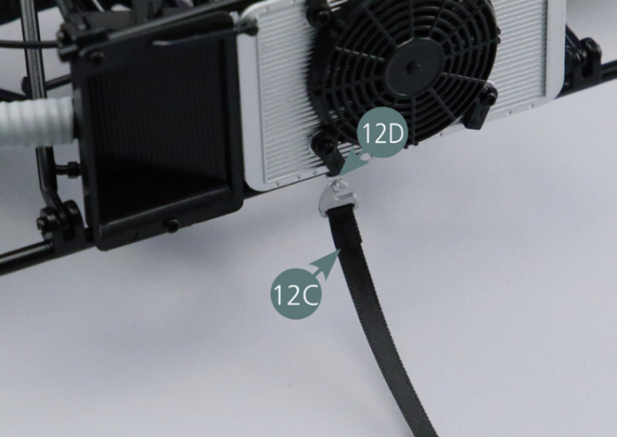
Step 3
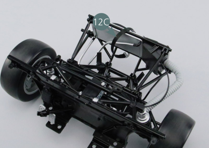
Attach one end of the strap of the spare wheel (12C), with the hook (12D), onto the radiator. Pass the strap behind the radiator.
Step 4
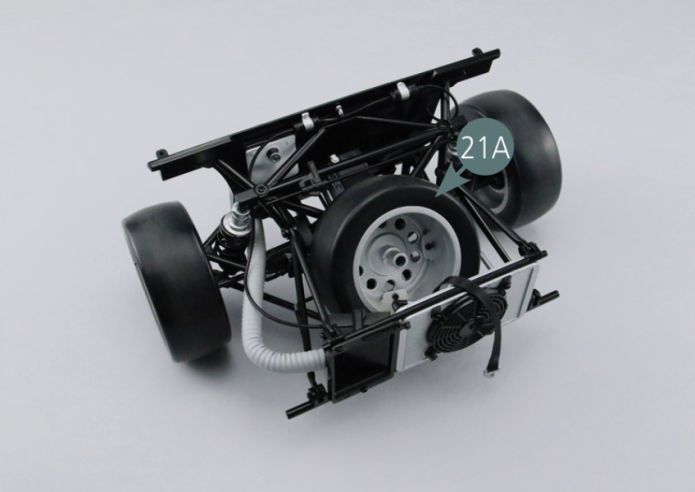
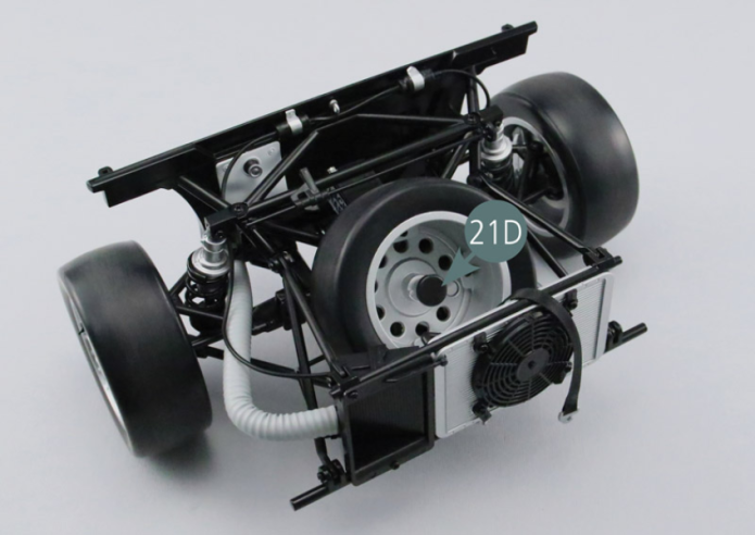
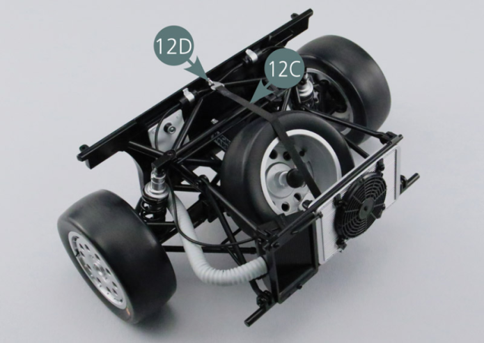
Position the spare wheel (21A) as shown in the photo. Insert the carrier (21D) in the central opening of the wheel. Attach the other end of the strap of the spare wheel (12C), with the other hook (12D), onto the firewall.
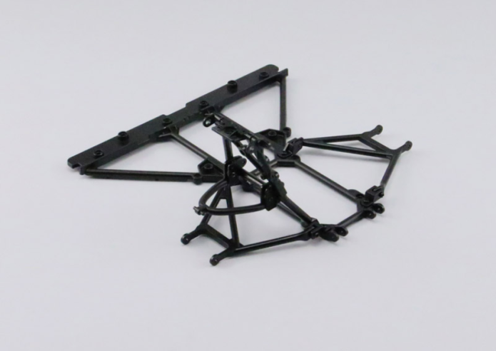
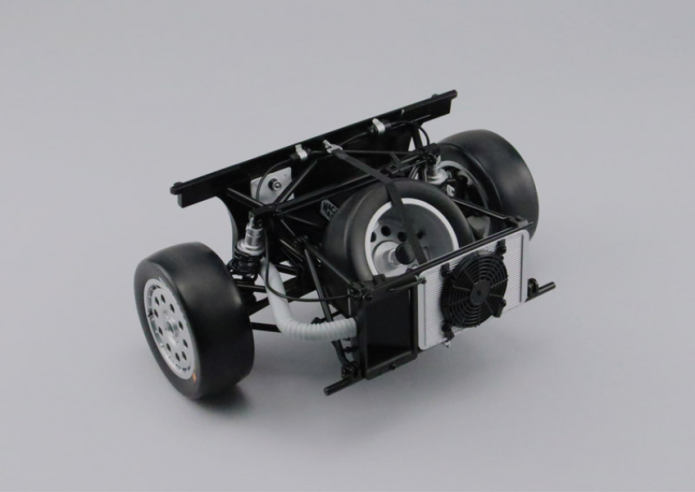
GENERAL VIEW
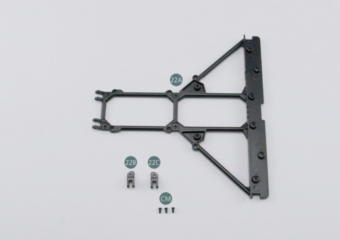
Kit 22 - REAR CHASSIS LOWER FRAME
Parts of kit
- 22A Lower rear frame
- 22B Left suspension arm support
- 22C Right suspension arm support
- Screw CM M 2.0 x 4 mm (x 3)
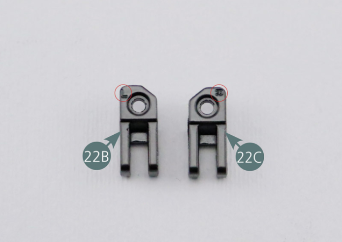
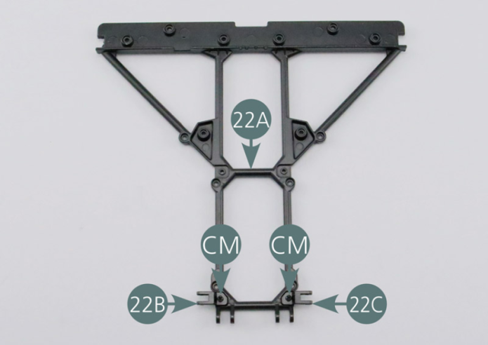
Step 1
Suspension arm supports are identified by the following letters: “L” (left) and “R” (right). After having carefully studied the photo of the assembly, position the suspension arm supports (22B & 22C) correctly on their respective sides of the lower frame (22A), then secure them with a CM screw.
GENERAL VIEW
Kit 23 - REAR LOWER SUSPENSION ARM
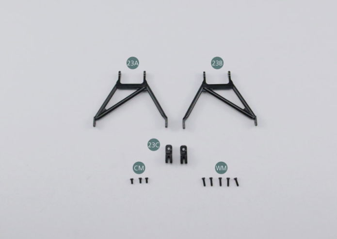
Parts of kit
- 23A Left rear lower suspension arm
- 23B Right rear lower suspension arm
- 23C Rear lower suspension arm support (x 2)
- Screw CM M 2.0 x 4 mm (x 3)
- Screw WM M 2.0 x 7 mm (x 5)
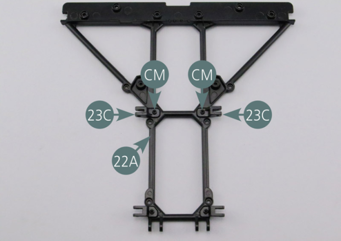
Step 1
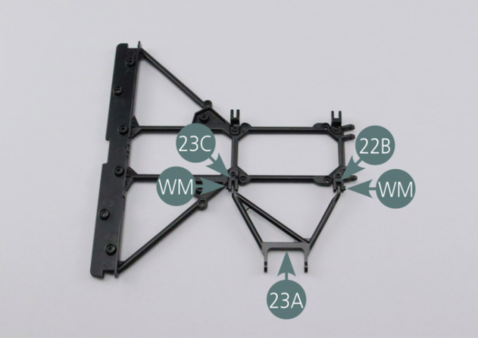
Position the two rear lower suspension arm supports (23C) on the lower rear frame (22A) and fasten them with two CM screws.
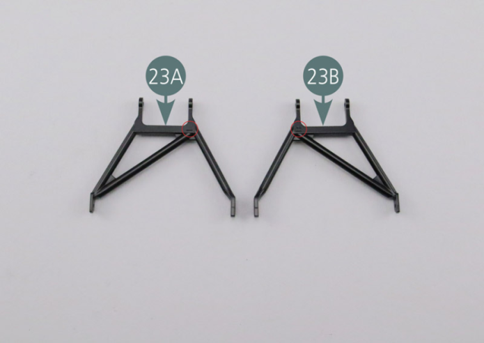
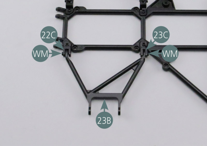
Step 2
The left lower suspension arm (23A) is identified by letter “L”, while the right lower suspension arm (23B) is identified by “R”. Position the lower left suspension arm (23A) on the supports (23C&22B), then secure with two WM screws. Position the right lower suspension arm (23B) on the supports (23C&22C), and secure with two WM screws.
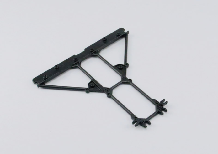
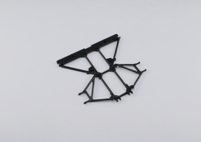
GENERAL VIEW
Kit 24 - REAR LOWER SUSPENSION ARM
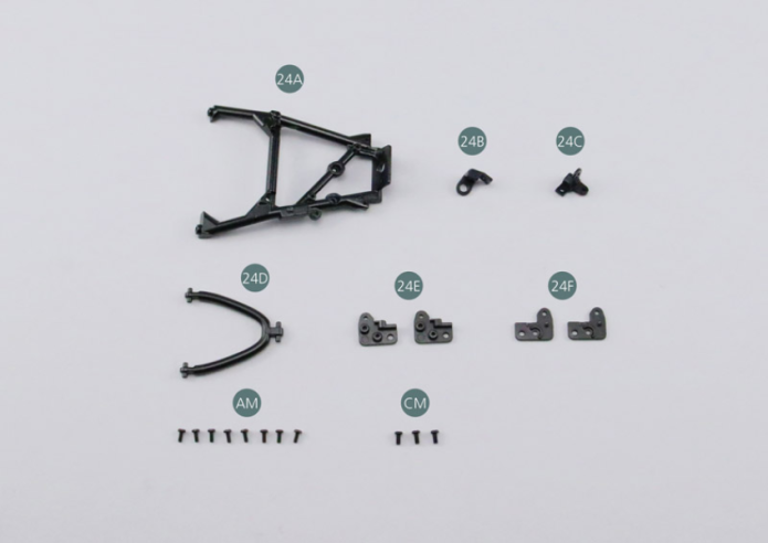
Parts of kit
- 24A Trapezoidal link arm, rear left
- 24B Link arm support #1
- 24C Link arm support #2
- 24D Left Rear Upper Suspension Arm
- 24E Suspension arm support #1 (x 2)
- 24F Suspension arm support #2 (x 2)
- Screw AM M 1.7 x 4 mm (x 8)
- Screw CM M 2.0 x 4 mm (x 3)
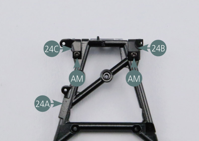
Step 1
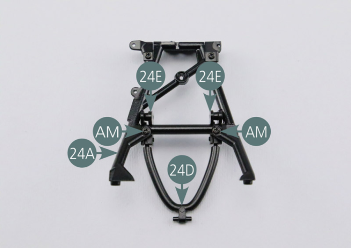
Place the link arm supports (24B&24C) on the left rear trapezoidal link arm (24A) then secure them with two AM screws.
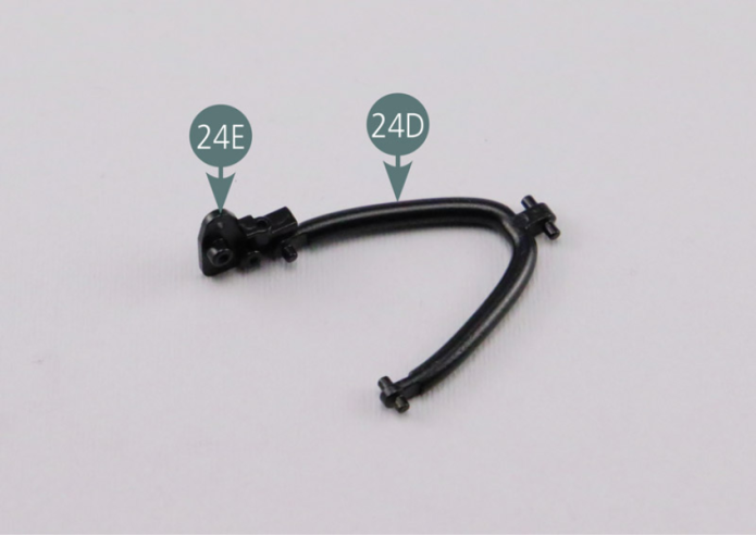
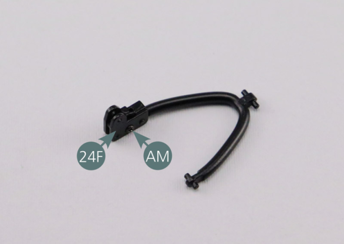
Step 2
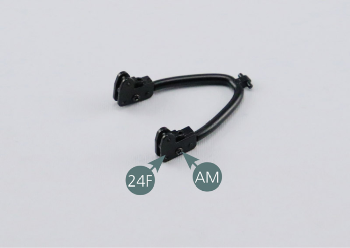
Position suspension arm support #1 (24E) on the left rear upper suspension arm (24D) by engaging the pin in the housing. Position suspension arm support #2 (24F) above as shown in the picture, then secure the two together with an AM screw.
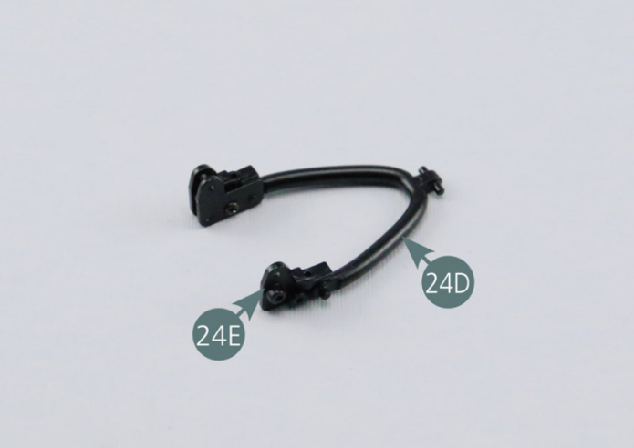
Step 3
Position the second suspension arm support #1 (24E) on the other end of the upper suspension arm (24D) by engaging the pin in the housing. Position the second suspension arm support #2 (24F) above as shown in the picture, then secure the two elements together with an AM screw.
Step 4
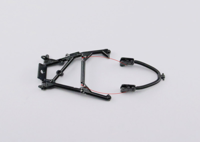
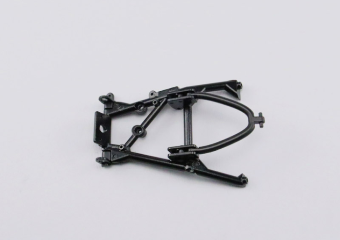
Place the ends of the suspension arm (24D) on the link arm brackets as shown in the photos. Fix the elements together with two AM screws
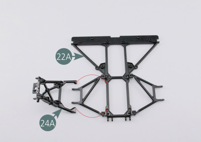
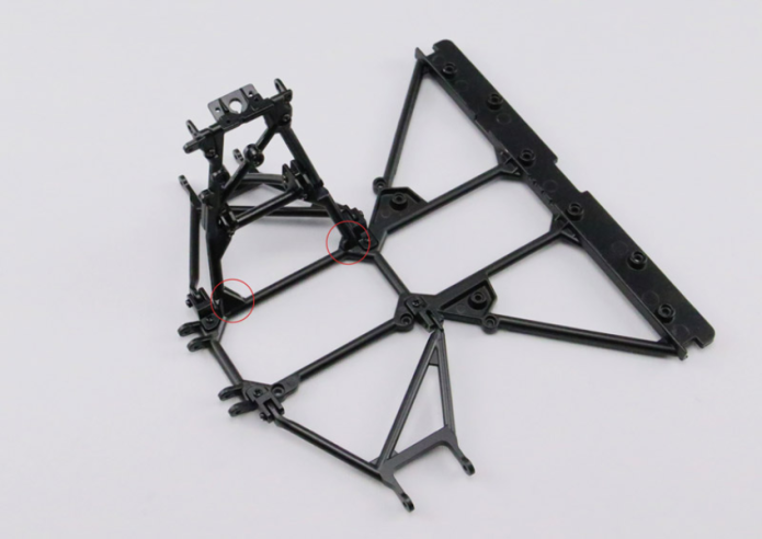
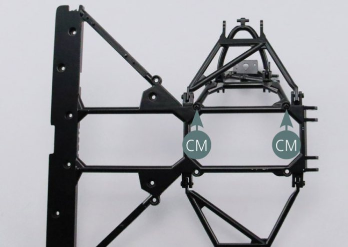
Step 5
Position the ends of the rear left trapezoidal link arm (24A) on the lower frame of the rear frame (22A). Secure the ends of the trapezoidal link arm with two CM screws.
GENERAL VIEW