English
 français
 Deutsch
 español
 italiano
 português


Box 7
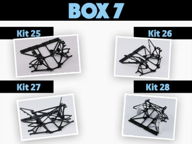
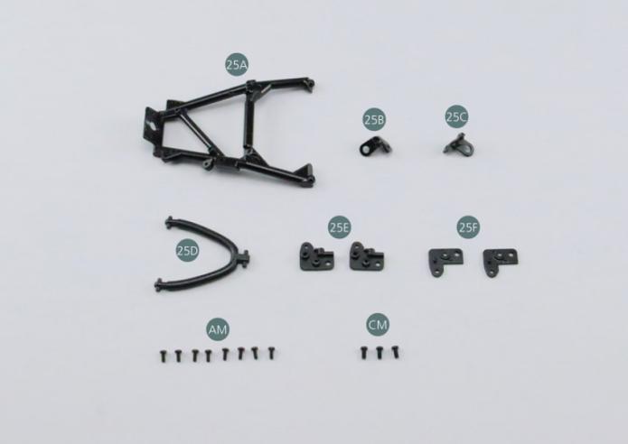
Kit 25 - UPPER RIGHT REAR SUSPENSION ARM
Parts of kit
- 25A Trapezoidal link arm, rear right
- 25B Link arm support #1
- 25C Link arm support #2
- 25D Upper suspension arm, rear right
- 25E Suspension arm support #1 (x 2)
- 25F Suspension arm support #2 (x 2)
- Screw AM M 1.7 x 4 mm (x 8)
- Screw CM M 2.0 x 4 mm (x 3)
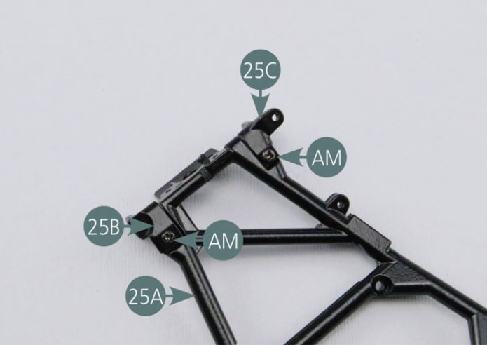
Step 1
Place the link arm supports (25B & 25C) on the right rear trapezoidal link arm (25A) then secure them with two AM screws.
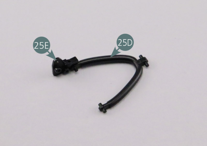
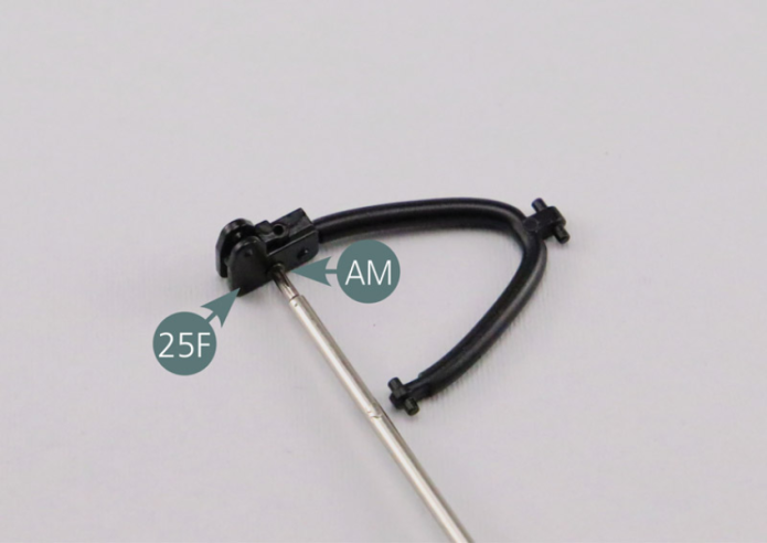
Step 2
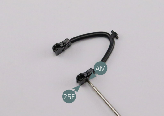
Position suspension arm support #1 (25E) on the right rear upper suspension arm (25D) by engaging the pin in the housing. Position suspension arm support #2 (25F) above as shown in the picture, then secure the two elements together with an AM screw.
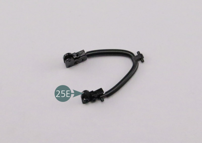
Step 3
Position the second suspension arm support #1 (24E) on the other end of the rear right upper suspension arm (25D) by engaging the pin in the housing. Position the second suspension arm support #2 (25F) above as shown in the picture, then secure the two elements together with an AM screw.
Step 4
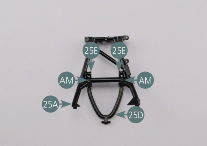
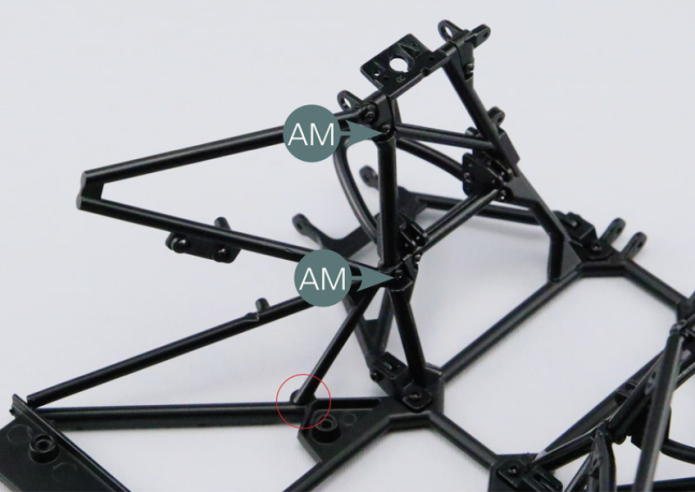
Place the ends of the suspension arm (25D) on the link arm supports as shown in the photos. Fix the elements together with two AM screws.
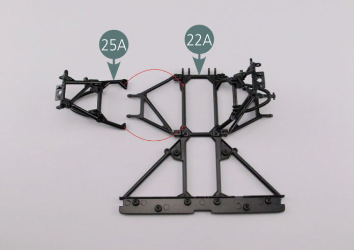
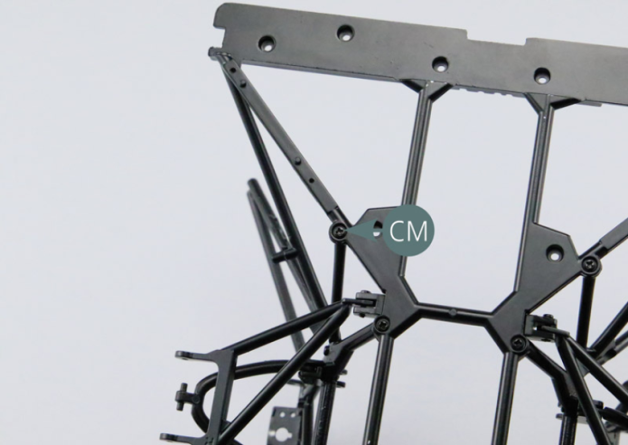
Step 5
Position the ends of the right rear trapezoidal link arm (25A) on the lower frame of the rear frame (22A). Secure the ends of the trapezoidal link arm with two CM screws.


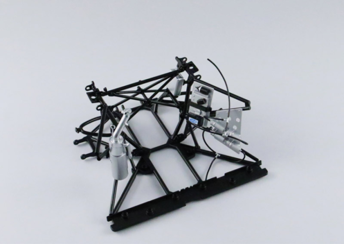
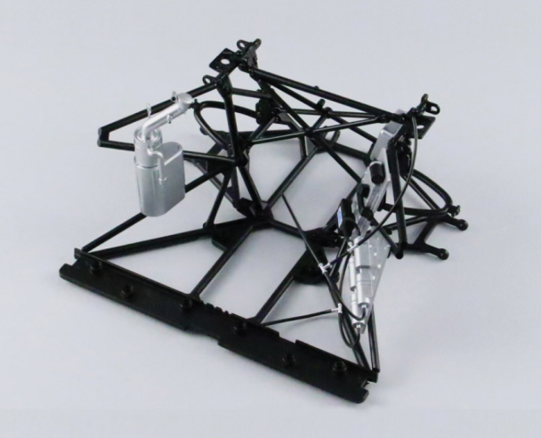
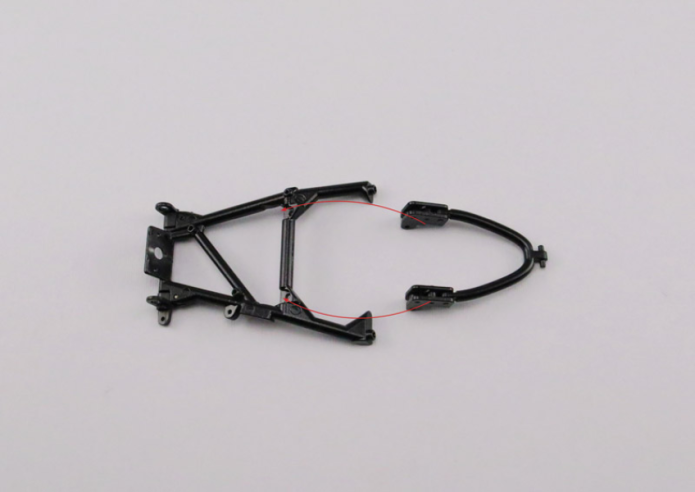
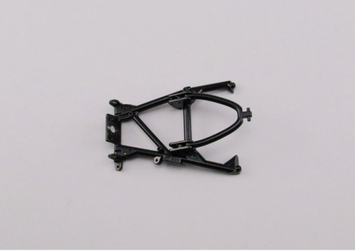
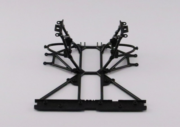
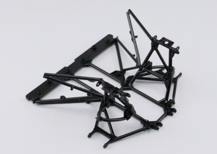
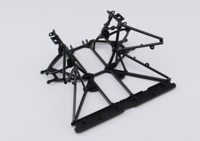
GENERAL VIEW
Kit 26 - REAR CHASSIS LOWER REINFORCEMENT FRAME
Parts of kit
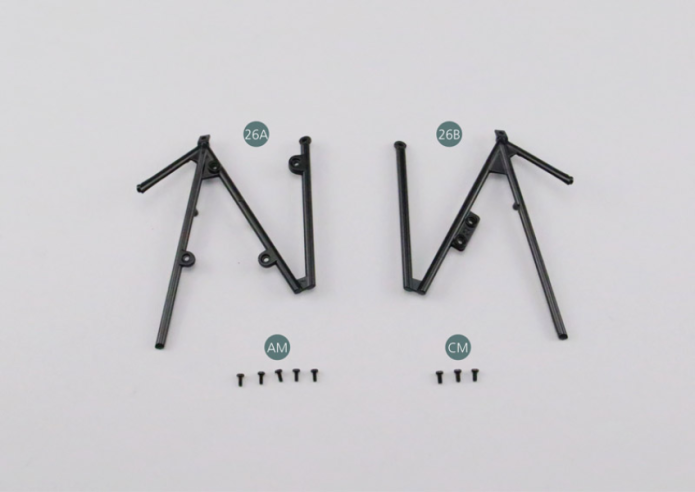
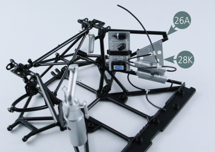
- 26A Left rear reinforcement frame
- 26B Right rear reinforcement frame
- Screw AM M 1.7 x 4 mm (x 5)
- Screw CM M 2.0 x 4 mm (x 3)
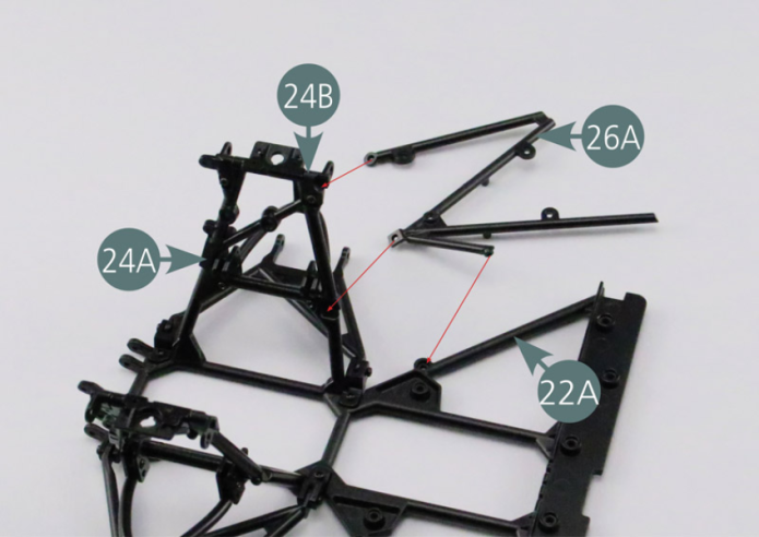
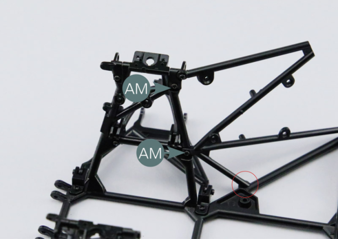
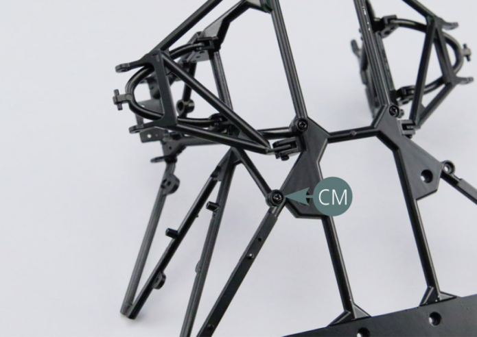
Step 1
Mount the left rear reinforcement frame (26A) on the lower frame of the rear chassis (22A) and on the rear left trapezoidal link arm (24A). Secure the reinforcement to the trapezoidal link arm (24A) with two AM screws. Secure the reinforcement frame to the lower frame of the rear chassis (22A) with a CM screw.
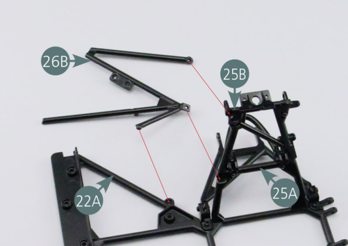
Step 2
Place the right rear reinforcement frame (26B) on the lower frame of the rear chassis (22A) and on the right rear trapezoidal link arm (25A). Secure the reinforcement to the trapezoidal link arm (25A) with two AM screws. Secure the reinforcement frame to the lower frame of the rear chassis (22A) with a CM screw.
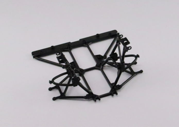
GENERAL VIEW
Kit 27 - CENTRAL REINFORCEMENT FRAME
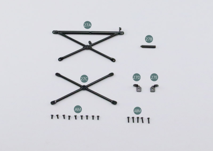
Parts of kit
- 27A External central reinforcement
- 27B Spacer
- 27C Inner central reinforcement
- 27D Left support
- 27E Right support
- Screw AM M 1.7 x 4 mm (x 9)
- Screw ABM M 1.7 x 6 mm (x 5)
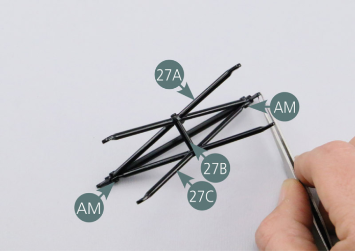
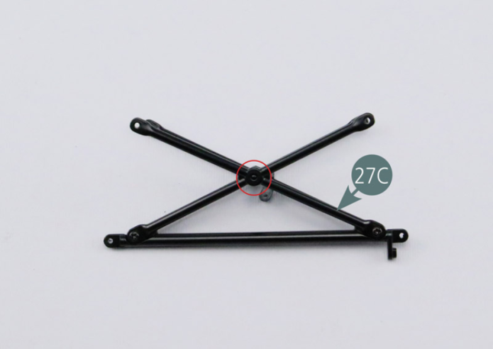
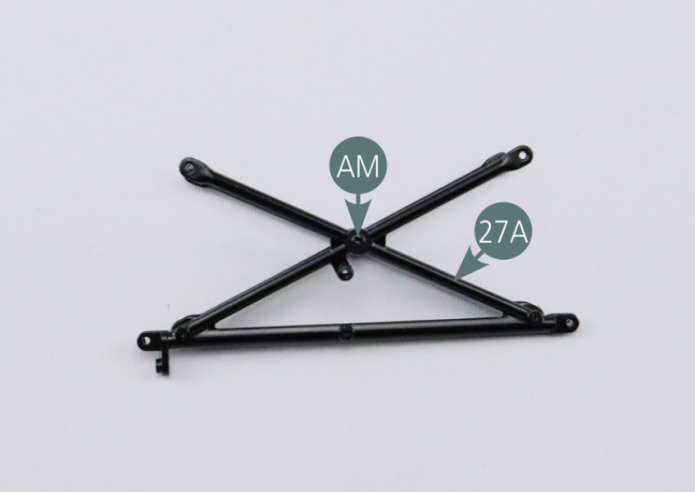
Step 1
Assemble the external central reinforcement (27A), the inner central reinforcement (27C) and the spacer (27B) as shown in the photo. Fasten the reinforcements (27A & 27C) together with two AM screws. Looking at the assembly from the inner central reinforcement (27C), locate the spacer pin. Secure the spacer (27B) with an AM screw on the opposite side (external central reinforcement 27A).
Step 2
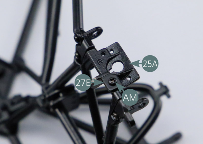
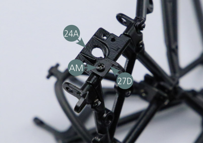
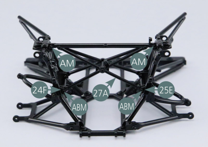
Place the right support (27E) on the right rear trapezoidal link arm (25A) and secure with an AM screw. Position the left bracket (27D) on the rear left trapezoidal link arm (24A) and secure with an AM screw.
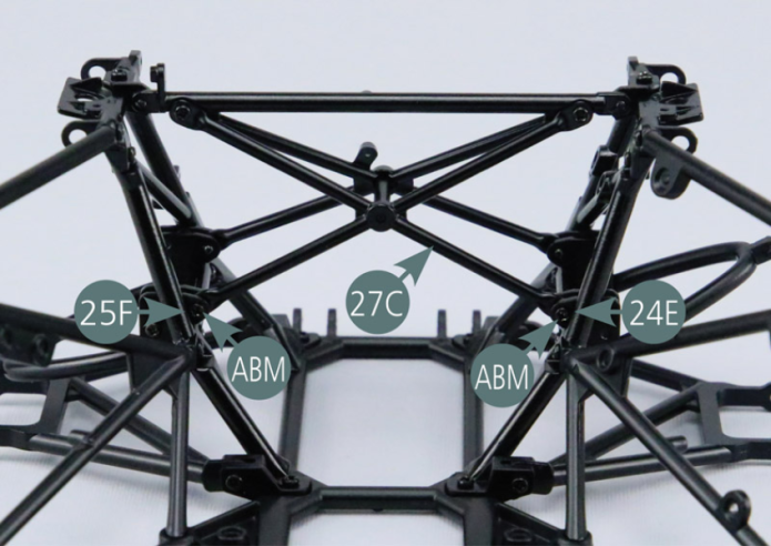
Step 3
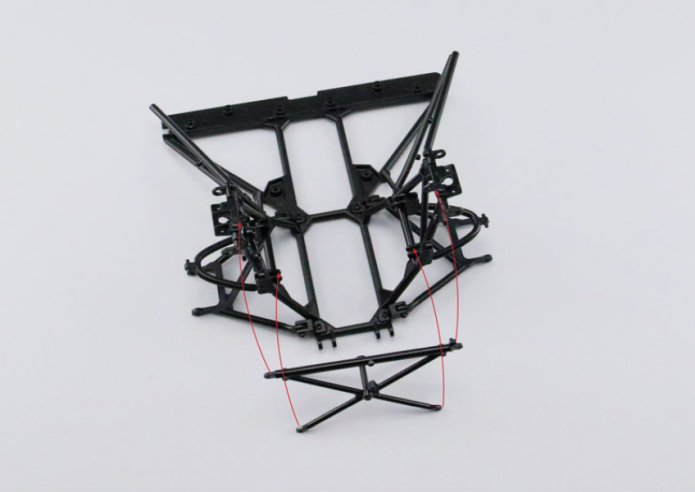
Position the central reinforcement frame (assembled in step 01) on the rear chassis frame as shown in the photo. Secure the central reinforcement frame to the rear chassis frame with two AM screws and four ABM screws (two for each side).
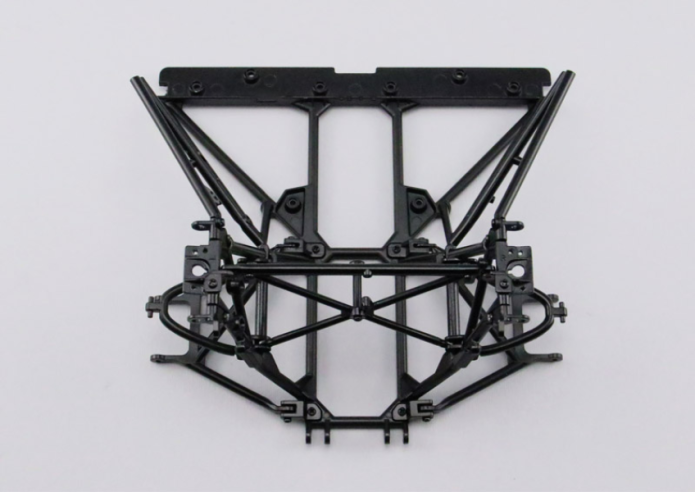
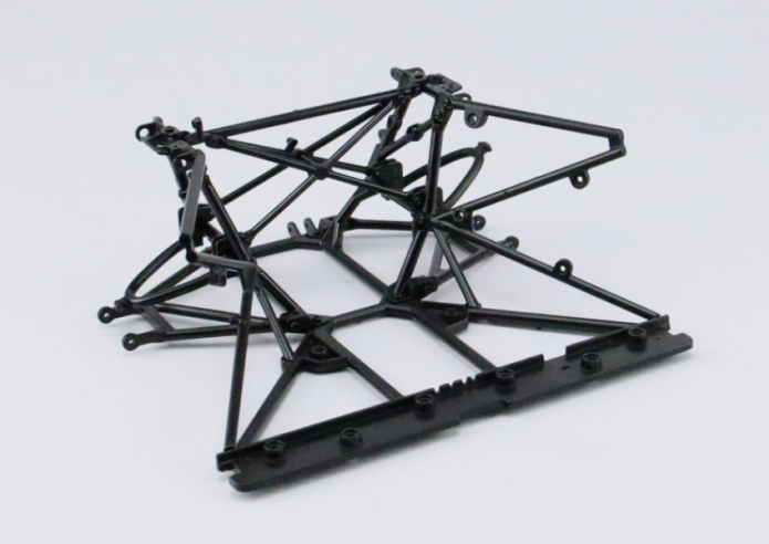
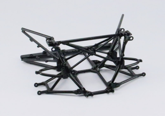
GENERAL VIEW
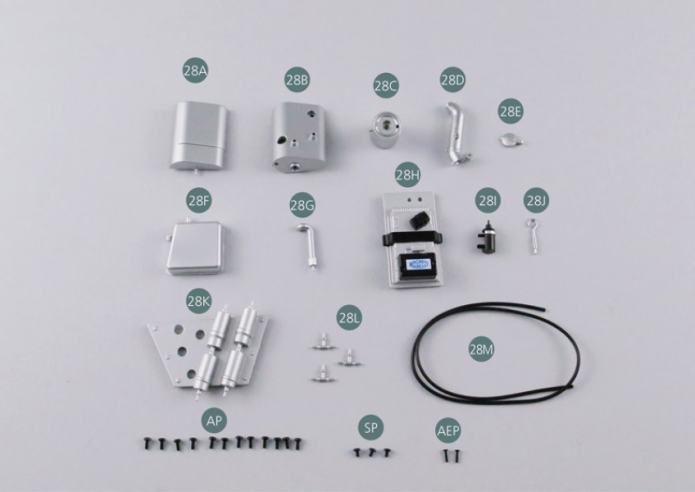
Kit 28 - Oil tank and fuel pumps
Parts of kit
- 28A Oil tank #1
- 28B Oil tank #2
- 28C Oil tank #3
- 28D Oil filler neck #4
- 28E Oil tank cap #5
- 28F Oil tank #6
- 28G Oil tank #7
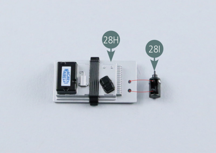
- 28H Electronic management center
- 28I Ignition coil
- 28J Oil dipstick
- 28K Fuel Pumps
- 28L T-fitting (x 3)
- 28M Fuel Hose
- Screw AP P 1.7 x 4 mm (x 12)
- Screw SP P 1.7 x 3 mm (x 3)
- Screw AEP P 1.2 x 5 mm (x 2)
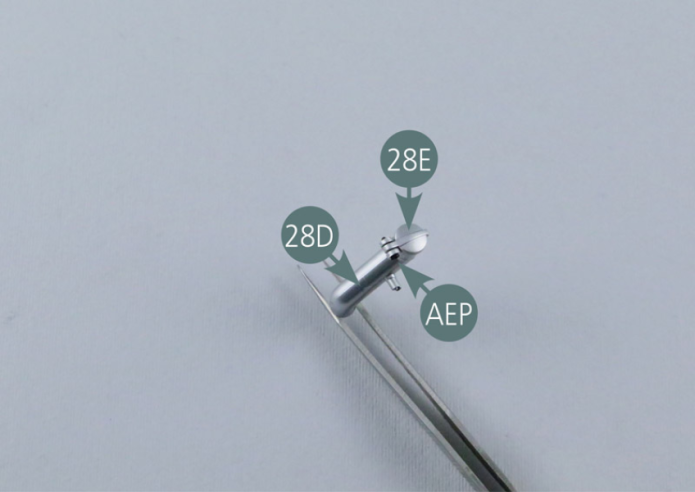
Step 1
Place the cap of the oil tank (28E #5) on the filler neck (28D #4) and secure with an AEP screw. Check if the cap (28E) opens and closes easily and if necessary, loosen the screw slightly.
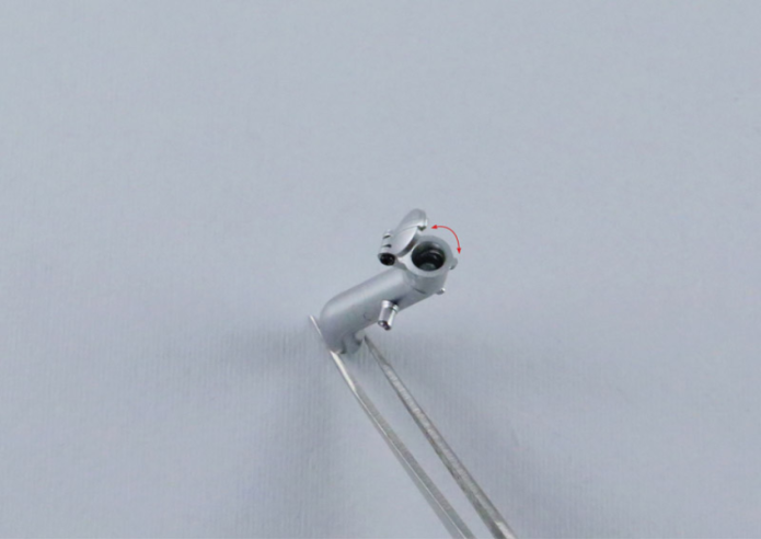
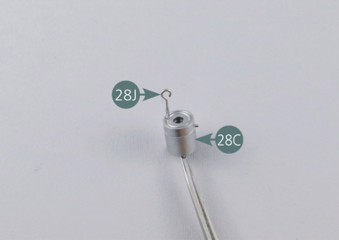
Step 2
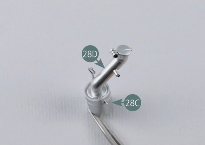
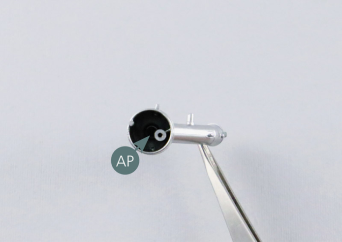
Position the oil dipstick (28J) on the oil tank (28C #3). Position the filler neck (28D #4) on the oil tank (28C #3). Secure the two elements together with an AP screw from below.
Step 3
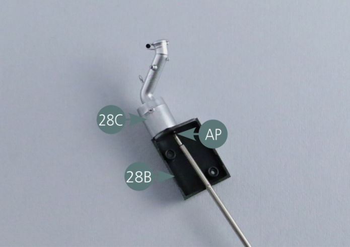
Position the oil tank (28C #3) on the oil tank (28B #2) and secure with an AP screw.
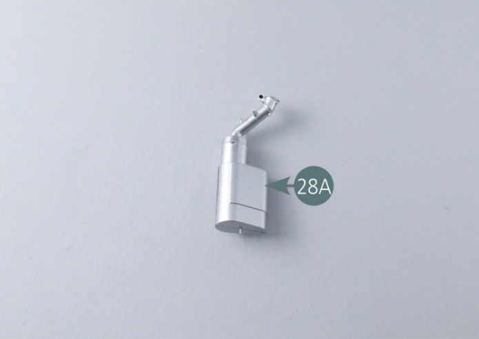
Position the oil tank (28A #1) on the oil tank (28B #2) and secure with two AP screws.
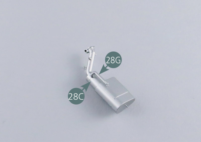
Position the oil tank (28G #7) on the oil tank (28C #3) as shown.

Step 4
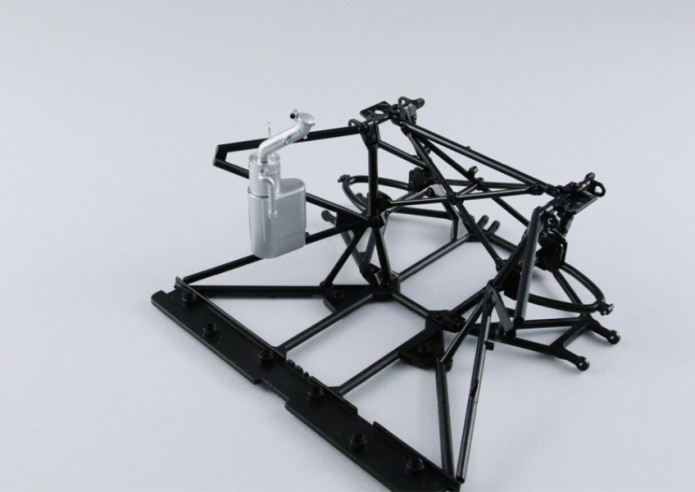
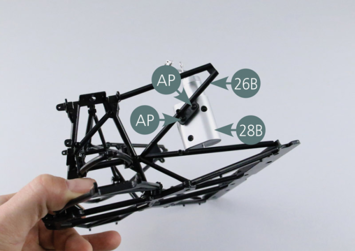
Place the assembly of the oil tank on the right rear frame reinforcement (26B) and secure with two AP screws.
Step 5
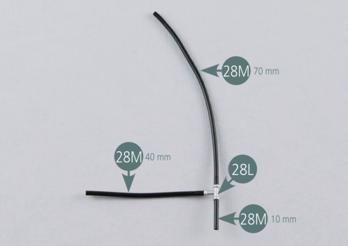
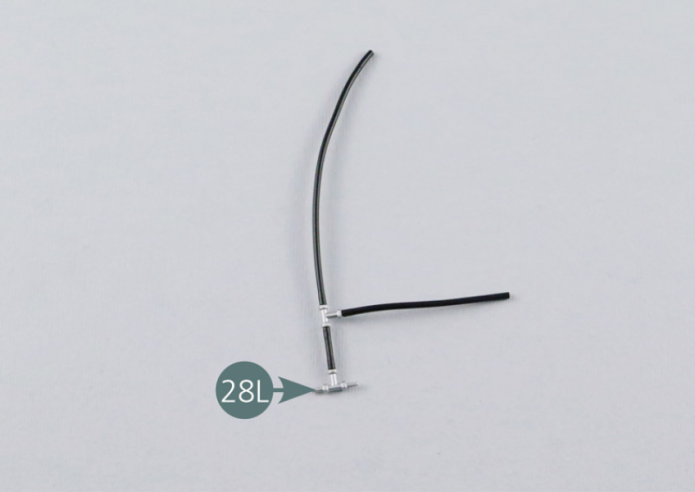
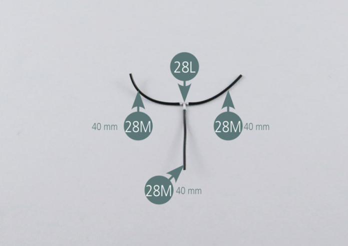
Cut three sections of 70mm, 40mm and 10mm long from the fuel hose (28M). Connect the three sections to a T-fitting (28L) as shown in the photo. Then connect the shorter section (10 mm) to a second T-fitting (28L).
Step 6
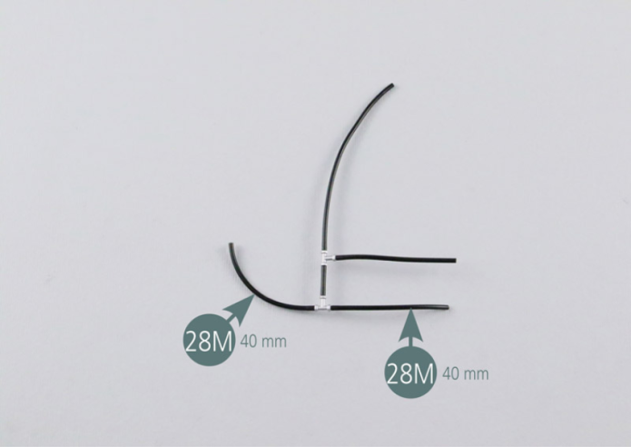
Cut two other sections of 40mm long from the fuel hose (28M) and connect them to the free ends of the T-fitting (28L) as shown.
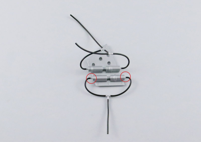
Step 7
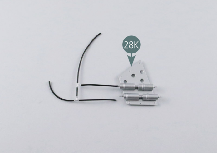
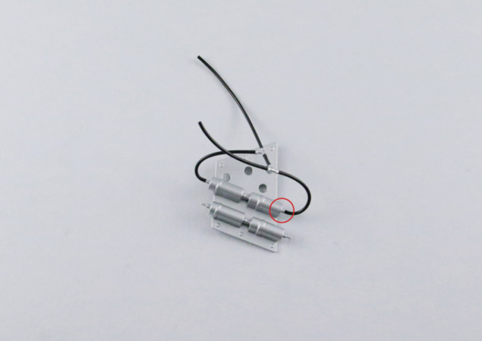
Connect the free end of the first 40 mm section to the fuel pump (28K). Then turn the assembly over and connect the opposite 40 mm section to the fuel pump (28K). Check the correct positioning of the connections as displayed in the picture.
Step 8
Cut three additional sections 40mm long from the fuel hose (28M) and connect them to the third T-fitting (28L) as shown. Connect two free ends of the sections to the fuel pump. Check the correct positioning of the connections after completing this assembly.
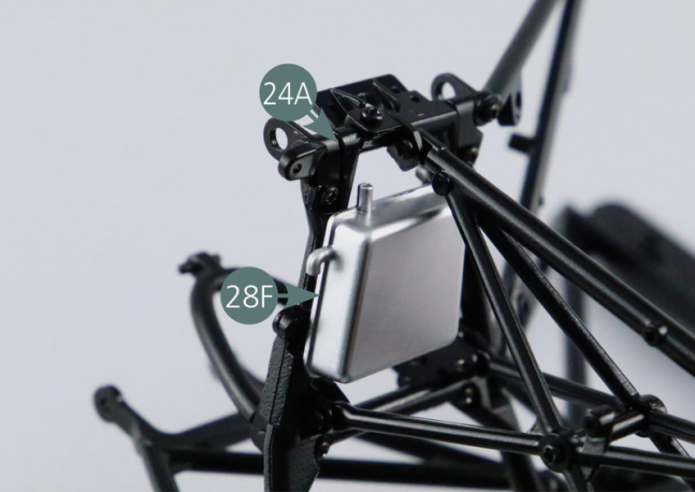
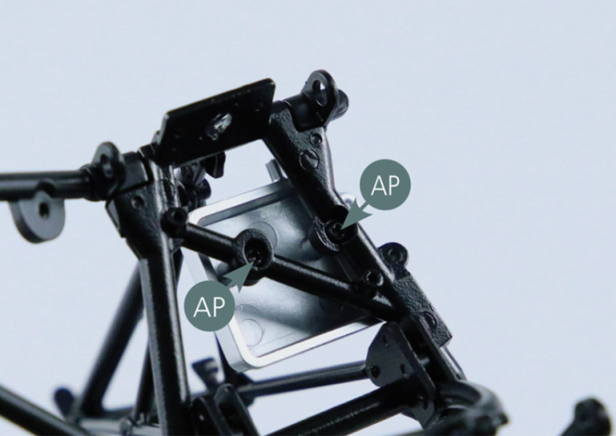
Step 9
Place the oil tank (28F #6) on the left rear trapezoidal link arm (24A) and secure with two AP screws.
Step 10
Place the ignition coil (28I) on the electronic management unit (28H).

Step 11
Position the electronic management unit (28H) on the left rear reinforcement frame (26A) and secure it with two AP screws.


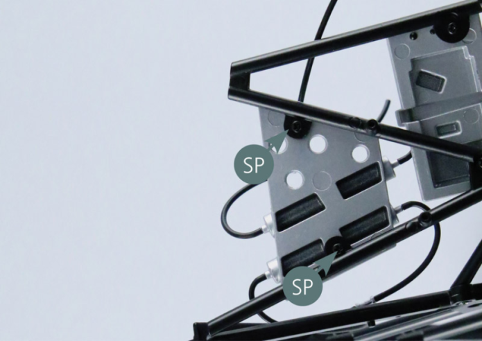
Step 12
Position the fuel pump support (28K) on the left rear reinforcement frame (26A) and secure it with two SP screws.
GENERAL VIEW