English
 français
 Deutsch
 español
 italiano
 português


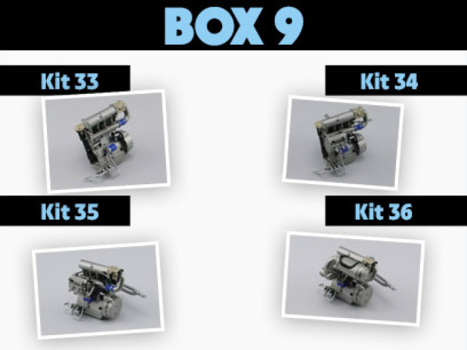
Box 9
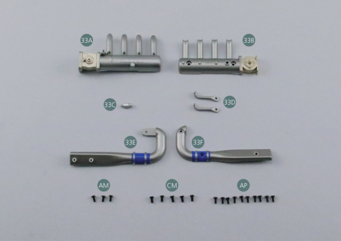
Parts of kit
- 33A Intake manifold #1
- 33B Intake manifold #2
- 33C Relief valve
- 33D Turbo support (x 2)
- 33E Supercharger manifold #1

Etape 1
- 33F Supercharger manifold #2
- Screw AM M 1.7 x 4 mm (x 3)
- Screw CM M 2.0 x 4 mm (x 5)
- Screw AP P 1.7 x 4 mm (x 10)
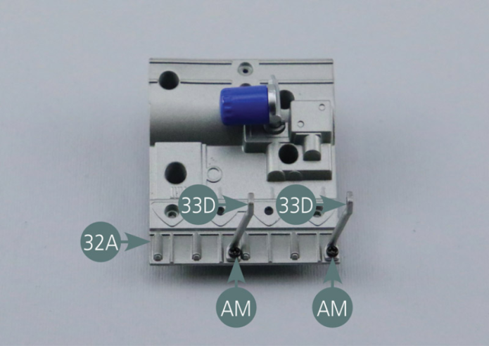
Positionner les deux supports de turbo 33D sur le bloc moteur gauche 32A et les fixer avec deux vis AM.

Etape 2
Position the two turbo supports (33D) on the left engine block (32A) and secure them with two AM screws.
Positionner le collecteur de suralimentation 33F sur le collecteur de suralimentation 33E et le fixer avec trois vis AP.
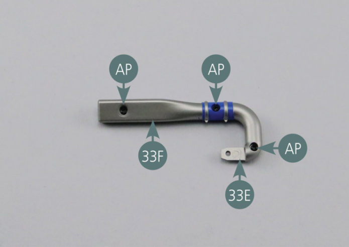
Position the turbo manifold (33F) onto the turbo manifold (33E) and secure it with three AP screws.

Etape 3
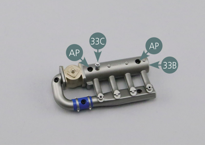
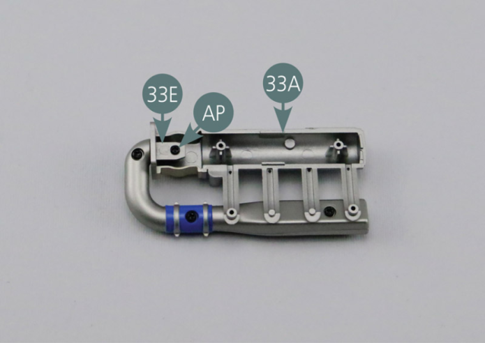
Position the intake manifold (33A) onto the turbo manifold (33E) as shown and secure with an AP screw. Complete the assembly by securing the intake manifold (33B) to the intake manifold (33A) with two AP screws, then position the relief valve (33C) onto the intake manifold (33B).

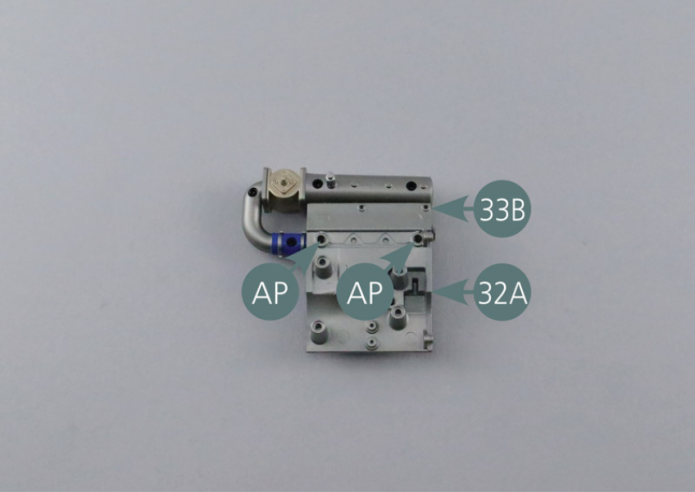
Positionner le collecteur d’admission 33B sur le bloc moteur gauche 32A et le fixer avec deux vis AP.
Etape 4
Position the intake manifold (33B) on the left engine block (32A) and secure with two AP screws.

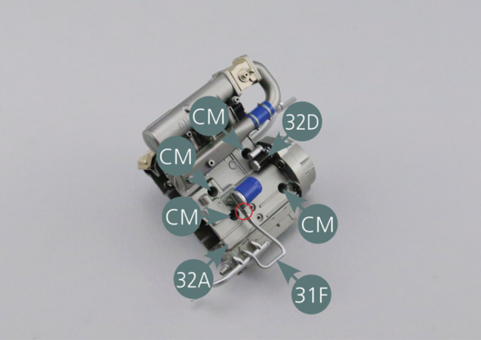
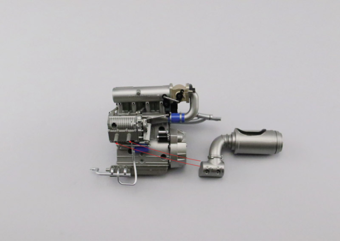
Assembler les blocs moteur droit 29A et gauche 32A en veillant à raccorder correctement la conduite d’huile 31F au filtre à huile 32C (cercle rouge).
Fixer les deux moitiés 29A et 32A du moteur avec quatre vis CM, puis positionner le démarreur 32D dans le carter de boîte de vitesses 31A.
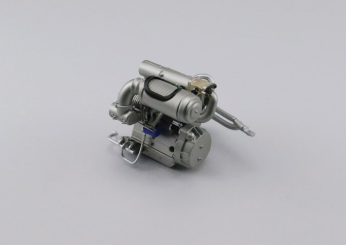
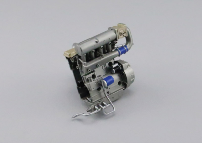
Vue générale
Assemble the right and left engine blocks (29A&32A) making sure to correctly connect the oil line (31F) to the oil filter (32C) (red circle). Secure the two motor halves (29A&32A) with four CM screws, then position the starter motor (32D) into the gearbox housing (31A).

GENERAL VIEW
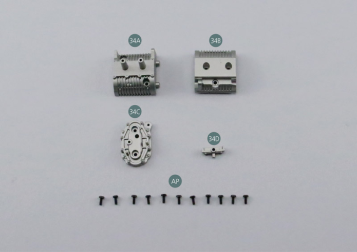
Parts of kit
Etape 1
- 34D Turbocharger element
- Screw AP P 1.7 x 4 mm (x 11)
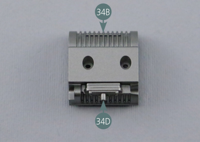
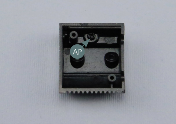
Positionner l’élément 34D sur la partie intérieure du turbocompresseur 34B et le fixer par en dessous avec une vis AP.


Etape 2
Position the element (34D) on the interior part of the turbocharger (34B) and secure from below with an AP screw.
Positionner la partie intérieure du turbocompresseur 34B sur le collecteur de suralimentation 33E et la fixer avec deux vis AP.
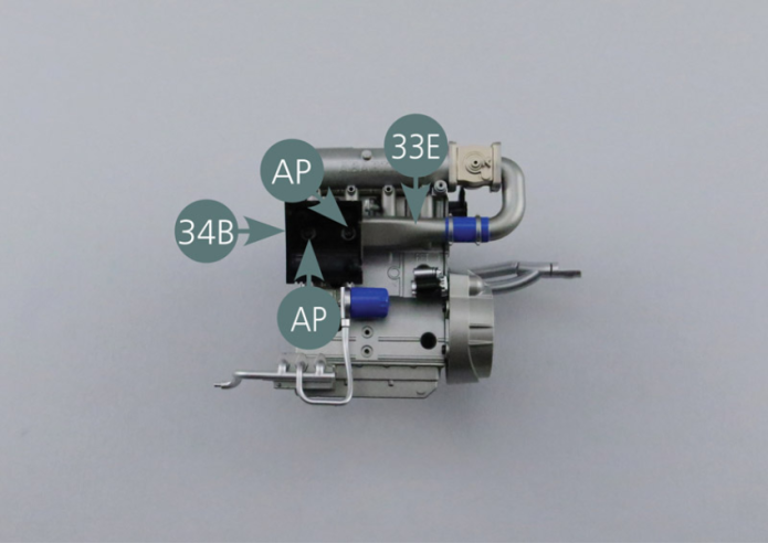
Position the inner part of the turbocharger (34B) on the supercharger manifold (33E) and secure it with two AP screws.

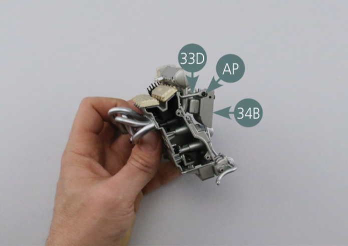
Etape 3
Secure the inner part of the turbocharger (34B) to the turbo element (33D) with an AP screw.
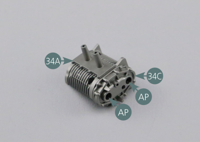
Positionner l’avant du turbocompresseur 34C sur la partie extérieure 34A et le fixer avec deux vis AP.
Positionner la partie extérieure du turbocompresseur 34A sur la partie intérieure 34B et la fixer avec deux vis AP.

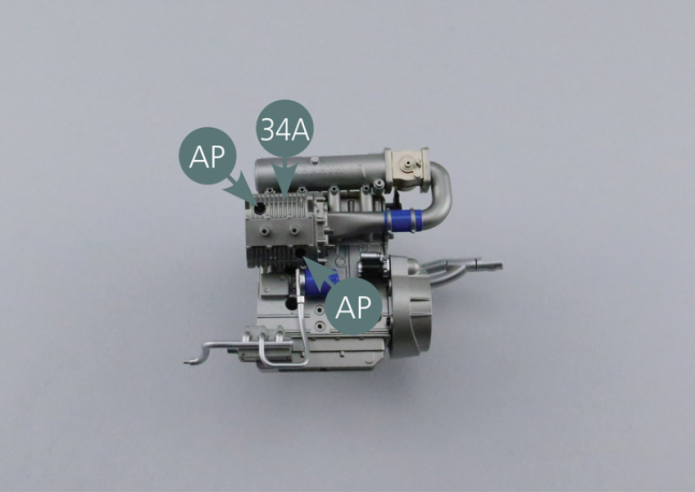
Etape 4
Position the front of the turbocharger (34C) on the outer part of the turbocharger (34A) and secure with two AP screws. Position the outer part of the turbocharger (34A) on the inner part (34B) and secure it with two AP screws.

Fixer le second support de turbo 33D sur l’avant du turbocompresseur 34C avec une vis AP.
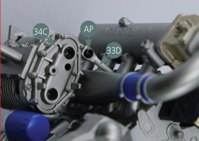
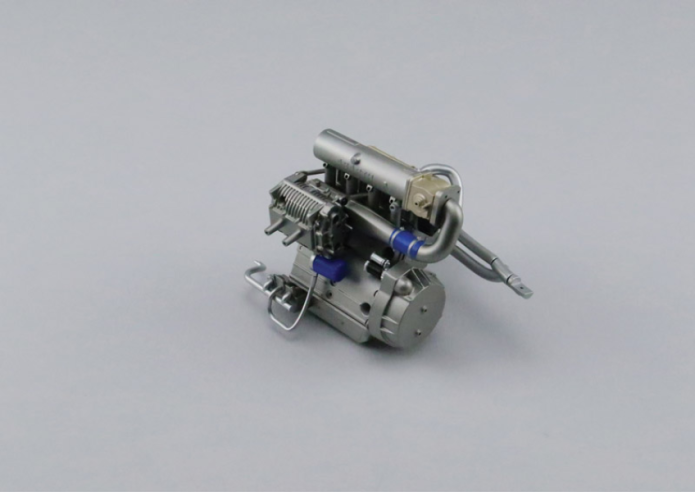
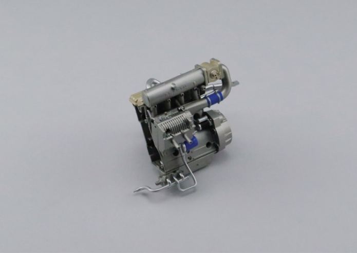
Vue générale
Secure the second turbo element (33D) to the front of the turbocharger (34C) with an AP screw.
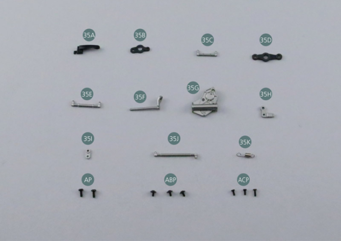
Kit 35 - Tringlerie d’accélérateur
Parts of kit

Etape 1
- 35H Lower accelerator lever
- 35I Front accelerator lever
- 35J Accelerator rod #4
- 35K Accelerator spring
- Screw AP P 1.7 x 4 mm (x 2)
- Screw ABP P 1.4 x 3 mm (x 3)
- Screw ACP P 1.4 x 3 mm (x 3)
Observer attentivement la tringle centrale 35D afin de bien repérer les extrémités «A» et «B».
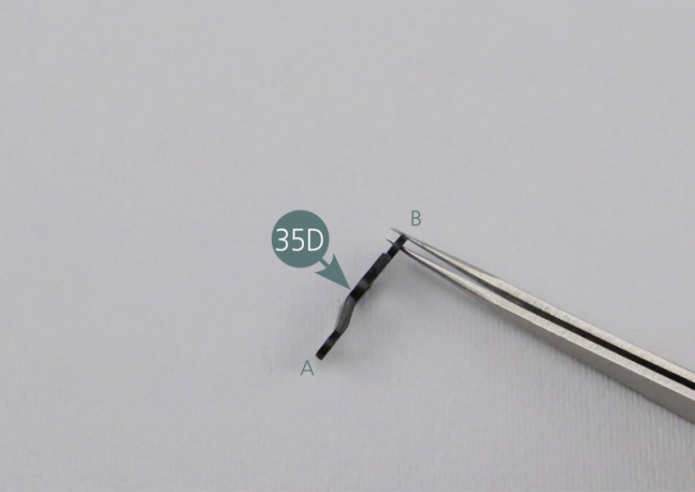
Carefully observe the centre rod (35D) in order to clearly identify the ends “A” and “B”.
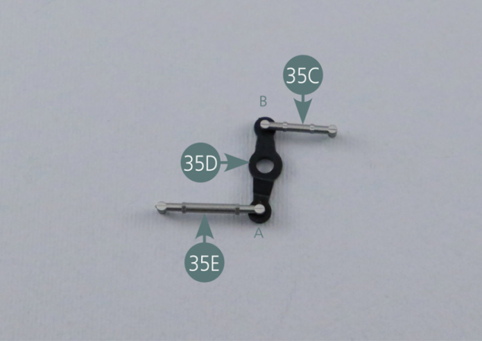
Place the accelerator rods (35C&35E) on the central rod (35D), taking care to distinguish between the two openings (A and B) located at the ends of the central rod.
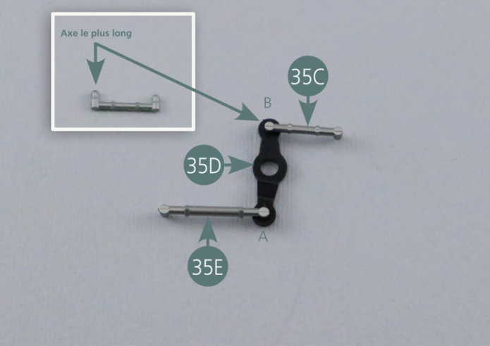
Etape 2
Insert the longer shaft of accelerator rod #1 (35C) into opening "B" in the central rod (35D).

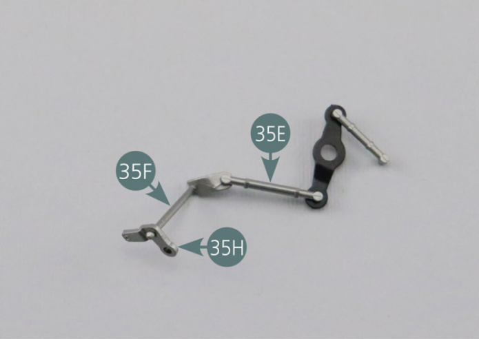
Positionner la tringle d’accélérateur 35F sur l’extrémité libre de la tringle d’accélérateur 35E, puis positionner le levier inférieur d’accélérateur 35H sur la tringle d’accélérateur 35F.
Veiller au positionnement correct de chaque pièce.
Etape 3
Place the accelerator rod #3 (35F) onto the free end of the accelerator rod #2 (35E), then position the lower accelerator lever (35H) onto the accelerator rod #3 (35F). Make sure each part is positioned correctly.

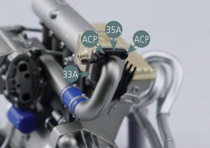
Positionner le verrouillage du ressort d’accélérateur 35A sur le collecteur d’admission 33A et le fixer avec deux vis ACP.
Etape 4
Place the accelerator spring lock (35A) onto the intake manifold (33A) and secure with two ACP screws.

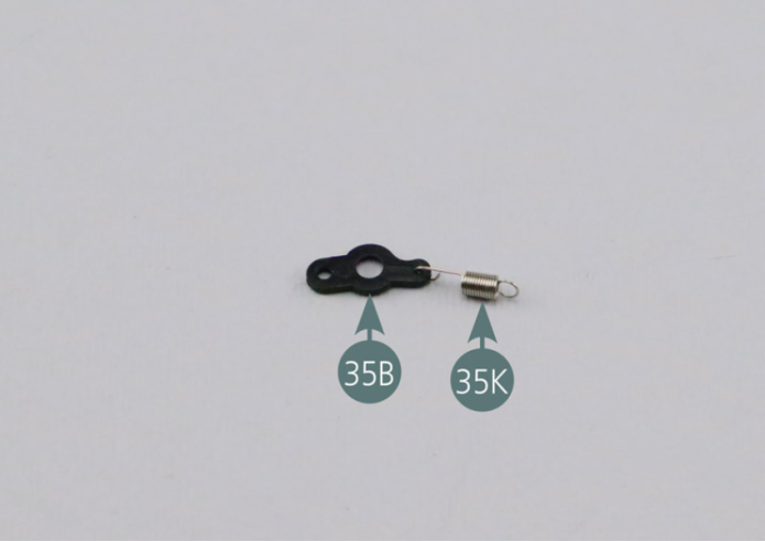
Positionner l’extrémité la plus longue du ressort d’accélérateur 35K dans le trou de la patte la plus mince du levier d’accélération supérieur 35B. Vérifier que l’assemblage est correct.
Positionner l’extrémité libre de la tringle d’accélérateur 35C dans le trou libre du levier d’accélération supérieur 35B, puis positionner le ressort 35K sur le verrouillage du ressort d’accélérateur 35A.
Etape 5
Position the longest end of the accelerator spring (35K) into the smallest opening of the upper accelerator lever (35B). Check that the assembly is correctly done. Place the free end of the accelerator rod #1 (35C) into the free opening of the upper accelerator lever (35B), then position the spring (35K) on the accelerator spring lock (35A).


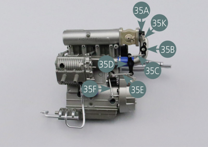
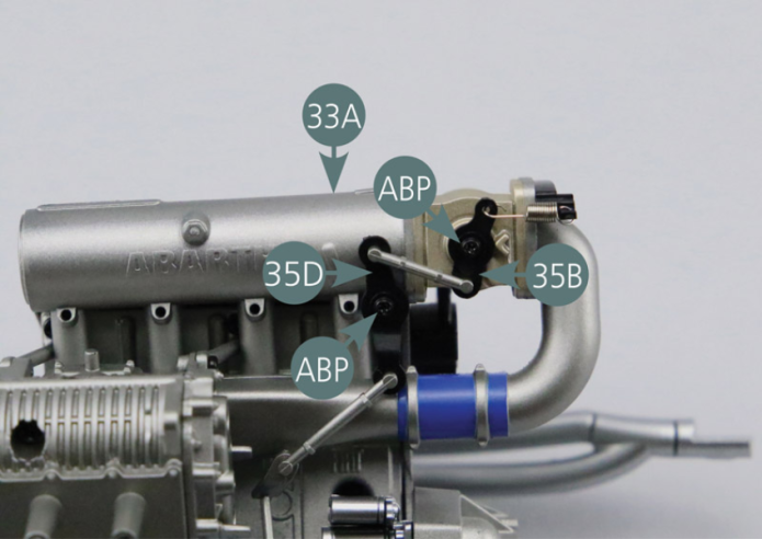
Fixer le levier d’accélération supérieur 35B et la tringle centrale 35D sur le collecteur d’admission 33A avec deux vis ABP comme indiqué sur la photo.

Etape 6
Secure the upper accelerator lever (35B) and centre rod (35D) to the intake manifold (33A) with two ABP screws - as shown in the picture.
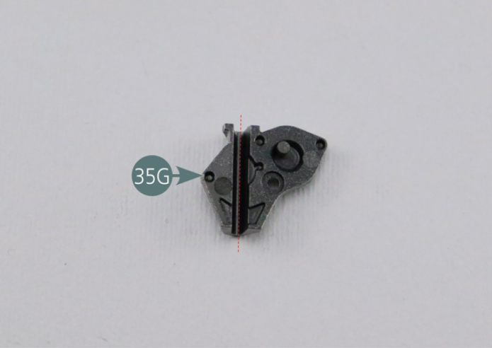
Le cache de tringlerie inférieure d’accélérateur 35G dispose d’une rainure servant à y loger la tringle d’accélérateur 35F (pointillé rouge).
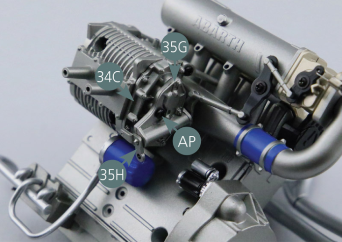
Positionner le cache de tringlerie inférieure d’accélérateur 35G sur la tringle d’accélérateur 35F et le fixer avec une vis AP.


Etape 7
The lower accelerator rod cover (35G) offers a groove to accommodate the accelerator rod #3 (35F) (red dotted line). Position the lower accelerator rod cover (35G) on the accelerator rod #3 (35F) and secure it with an AP screw.
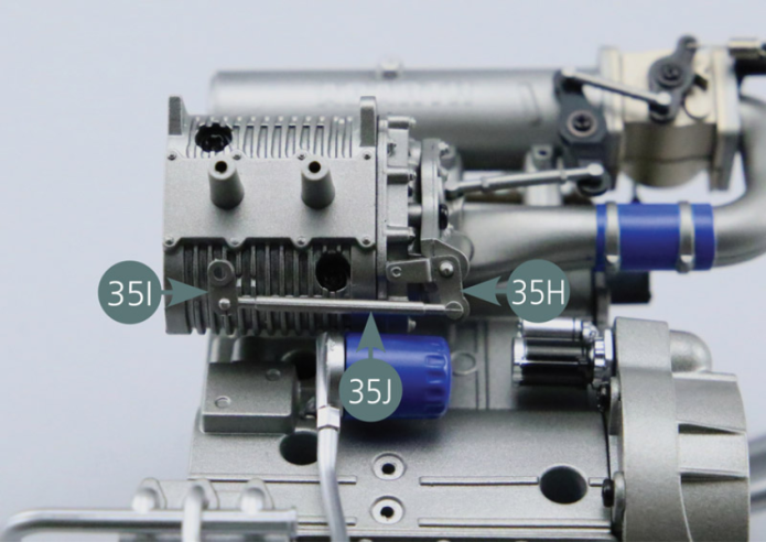
Positionner le levier avant d’accélérateur 35I sur la tringle d’accélérateur 35J. Observer la différence entre les deux extrémités de la pièce 35J (petite tête et grosse tête).
Positionner la tringle d’accélérateur 35J sur le levier inférieur d’accélérateur 35H.
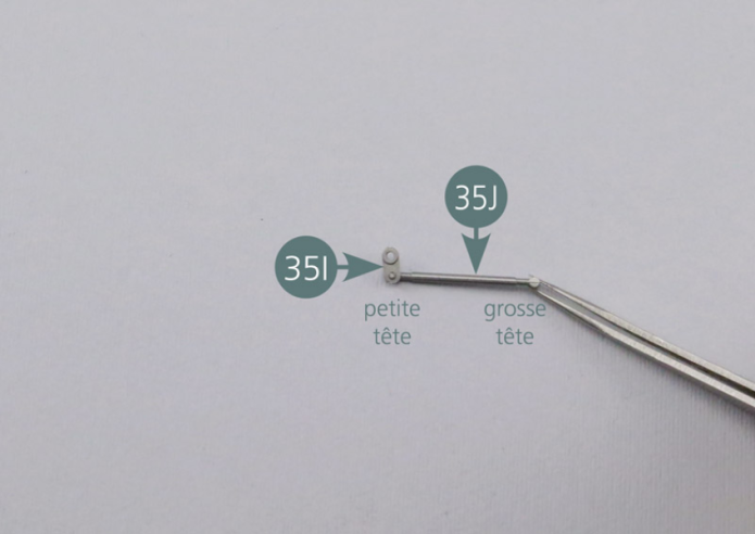
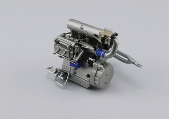
Vue générale
Place the front accelerator lever (35I) on the accelerator rod #4 (35J). Observe the difference between the two ends of this part (35J) (small head and bigger head). Place the accelerator rod #4 (35J) on the lower accelerator lever (35H).


GENERAL VIEW
Parts of kit
Etape 1
- 36D Air box manifold (outer part)
- Screw AP P 1.7 x 4 mm (x 5)
- Screw RP P 1.7 x 3 mm (x 2)

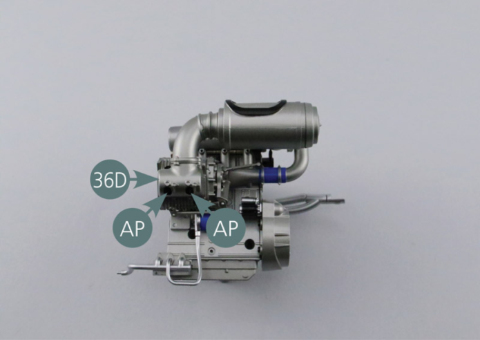
Positionner le collecteur de boîte à air 36C sur le collecteur 36D et le fixer avec deux vis AP.
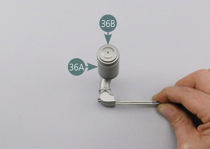
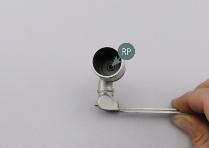
Positionner la boîte à air 36A sur le collecteur assemblé 36C-36D et la fixer depuis l’intérieur avec une vis RP.
Obturer la boîte à air 36A avec le couvercle 36B.


Place the air box manifold inner part (36C) onto the manifold outer part (36D) and secure with two AP screws. Position the air box (36A) on the assembled manifold (36C&36D) and secure it from the inside with an RP screw. Close the air box (36A) with the cover (36B).

Etape 2

Positionner la boîte à air assemblée sur le turbocompresseur 34A (flèches rouges) et la fixer avec deux vis AP.
Vue générale
Place the assembled air box on the turbocharger (34A) (red arrows) and secure with two AP screws.